Article

Large Piston Error Detection Method Based on the Multiwavelength Phase Shift Interference and Dynamic Adjustment Strategy

1
Key Laboratory of Infrared System Detection and Imaging Technologies, Shanghai Institute of Technical Physics, Chinese Academy of Sciences, Shanghai 200083, China
2
University of Chinese Academy of Sciences, Beijing 100049, China
*
Author to whom correspondence should be addressed.
Photonics 2022, 9(10), 694; https://doi.org/10.3390/photonics9100694
Submission received: 29 August 2022 / Revised: 19 September 2022 / Accepted: 21 September 2022 / Published: 26 September 2022
(This article belongs to the Special Issue Active Optics)

Abstract

:
As the loading space in rockets and mirror fabrication technology is limited, optical systems in space cannot have large optical apertures. However, the successful launch and excellent performance of the James Webb Telescope indicate that segmented mirrors can help realize large-aperture optical systems in space, owing to the fold–unfold mechanism in the telescope. However, all segments in the segmented mirror should be co-phased so that it is equivalent to a monolithic mirror. The co-phasing problem is significant in optical systems in space because of their low error tolerance. Owing to some accident factors, the piston error can be more than 1 mm after the unfolding process. Here, we introduced a multiwavelength interference method and dynamic adjusting strategy, aiming to solve the two problems of co-phasing: large detection range (~2 mm) and high detection precision (<1/20λ). Numerical simulations were performed, and a 400 mm aperture-segmented spherical mirror system was used to verify this method. The original piston error was set to 1 mm, after the coarse co-phasing, and the residual piston error to less than half the wavelength of the monochromatic light; for fine co-phasing, the achieved detection precision was approximately 1.2 nm.

1. Introduction

The development of science has enabled humankind to further observe and study the universe. Therefore, the demand to observe darker and remote objects has increased, leading to the requirement of telescopes with larger apertures. As factors such as materials, manufacturing techniques, and transportation limit the feasibility of manufacturing a large, monolithic aperture mirror, alternative methods need to be developed. Recently, the use of a few smaller mirrors to function similarly to a large mirror has proven to be an effective plan by some successful telescope precedents such as Keck, SALT, and HET; the most noteworthy example is the James Webb Space Telescope (JWST) (successor of the Hubble Space Telescope) that was launched on 25 December 2021.
However, segmented design leads to new requirements, including that all the segments should be aligned to closely resemble the ideal monolithic mirror, which is termed as co-phasing of the segmented mirror. We assume that each segment has six rigid-body degrees of freedom: three translational (x, y, z) and three rotational (tx, ty, tz), of which three (x, y, tz) are considered stable owing to their mechanical support structure; it is unnecessary to align them with optical precision. The remaining three degrees of freedom are piston error (z), tip error (tx), and tilt error (ty), respectively. These three errors are called co-phasing errors. Detection and adjustment of co-phasing errors is the most critical issue for a segmented mirror because a co-phasing error at even the µm level can cause a significant decline in the performance of segmented telescopes. The influence of co-phasing errors on segmented mirrors has been studied [1,2]. It is reported that all segments should be carefully co-phased to avoid diffraction effects in the final image. The piston error should be within 100 nm in the case of Keck [3]. The piston error should be maintained below λ / 20 , where λ is defined as the working wavelength of the telescope.
For ground-based segmented telescopes (such as Keck), the piston error can reach more than tens or even a hundred micrometers [4]; for space-based segmented mirrors, considering the accident and instability of the unfold and locking equipment, the predicted piston error should be more than 1 mm.
The interference method is commonly used for optical detection. The advantage of optical interference is the impressive high measurement precision and the relative ease of application. It has been used in many high-precision detection fields, such as mirror-surface-figure measurement. Owing to its high measurement precision, interferometry has also been applied for the detection of co-phasing errors in segmented mirrors [5,6]. An advantage of the interference method is that it can simultaneously calculate piston, tip, and tilt errors. However, the problem of interference of monochromatic light still exists, because it cannot accurately measure the piston error over more than half a wavelength. For this problem, some excellent research about the dual-wave interfermeotro has been carried out [7,8]; furthermore, dual-wave or white light interference techniques can also be used to expand the detection range of co-phasing [9,10]. However, as the detection range is expanded, the detection error also increases. Usually, a large detection range can be applied to coarse phasing processes and a small detection range for fine phasing processes. However, for a large piston error (~1 mm), the coarse phasing process cannot transition to the fine phasing process owing to the enhancement of the detection error (laser monochromaticity, vibration, air disturbance, detector noise, etc.). To resolve this problem, we introduced a multi-wave interference plan based on the dual-wave interference technology using a tunable laser as the light source, i.e., the multiwavelength phase shift interference (MPI) method. The piston error converges step-wise through the dynamic adjustment strategy. Further, for the convenience of adjusting the mirror surface, we used a reference mirror to generate the reference light rather than shear interference to achieve the correct wavefront information of each segment of the mirror. The MPI method can realize a large detection range and satisfactory detection precision, and measure the entire aperture in a relatively short time. Furthermore, it does not affect the working time of the telescope as it only requires the laser source rather than starlight.
However, the drawback of interference method is that illuminating a large aperture at its center of curvature is often not possible; therefore, it is hard to measure all segments at one time in the engineering practice. Several different techniques of co-phasing in a segmented mirror have been studied, including the use of the Shark–Hartman sensor or pyramid sensor to measure the co-phasing error [11,12], and the application of the dispersion fringe sensor (DFS) and curvature sensor to detect the co-phasing in segments [13,14]. A few technologies do not need to use those special devices but only need a sample optical device; for example, the intensity information of the image plane is used to correct the co-phasing error by the computer arithmetic [15,16]. For the JWST co-phasing process, the Dispersed Hartmann Sensor (DHS) and DFS were used for the coarse phasing [17], the piston capture range was designed as 300 μm, owing to the segment’s depth of focus being about 85 μm for JWST. However, compared with the interference method, those methods which use starlight could not achieve a larger capture range (>1 mm) of co-phasing detection than the interference method because, with starlight, it is hard to achieve great monochromaticity as with a laser source, while the large capture range can significantly increase the fault-tolerance of segmented mirrors; therefore, the MPI method is advisable in case a large capture range is required.
The segments used in this study are based on a pre-research project of the Ministry of Science and Technology of China. An optical system with a 6 m-aperture primary mirror with 20 segments was designed for this project. These segments were formed by using eight fan-shaped mirrors and 12 octagon mirrors owing to the requirement of this pre-research project; the geometrical shape is illustrated in Figure 2. To verify the validity of the MPI method, a series of experiments were conducted in a scaled-down segment system.
The remainder of the paper is organized as follows. In Section 2, we introduce the theory and methodology of MPI. Section 3 describes the simulation result and Section 4 explains the experimental setup and result. Finally, Section 5 and Section 6 present the disccusion and conclusions.

2. Methodology

2.1. Phase Shift Interferometry Basis

We first introduce the principle of classical phase shift interference method. A diffraction limited optical system was assumed; the only optical aberrations considered were co-phasing errors (i.e., piston, tip, and tilt errors), and the light source was assumed to be monochromatic. We defined ( x , y ) as the coordinates in the image plane. Then, the intensity function in the image plane can be written as:
I ( x , y ) = | E R + E T | 2 ,
where E R and E T are the reference and test light fields, respectively, and can be expressed as the complex amplitude of plane wave as follows:
E R = A e i ( w 1 t 1 φ ( x , y ) ) ,
E T = B e i ( w 2 t 2 φ ( x , y ) ) ,
where A, B and φ ( x , y ) , φ ( x , y ) are the amplitude and phase of each wave, respectively, w = 2 π f is the phase speed in vacuum, t is the time, and we assume w 1 t 1 = w 2 t 2 . Then, Equation (1) becomes:
I ( x , y ) = A 2 + B 2 + 2 A B cos ( φ ( x , y ) φ ( x , y ) ) ,
or
I ( x , y ) = 1 + γ ( cos φ ( x , y ) cos φ ( x , y ) + sin φ ( x , y ) sin φ ( x , y ) )
where γ = 2 A B / A 2 + B 2 is the interference fringe constant.
Generally, some phase shift is needed in Equation (5) to calculate φ ( x , y ) [7]. For example, for the four-step phase shift,
φ ( x , y ) = tan 1 1 n 1 n ( I 2 I 4 ) 1 n 1 n ( I 1 I 3 ) ,
where n is the number of frames in one time measurement, I1 to I4 was calculated by Equation (4) when φ ( x , y ) in Equation (4) is equal to 0, π/2, π, 3π/2 respectively.
The phase shift interference method can conveniently detect the wavefront of the telescope in the image plane, and subsequently obtain the co-phasing error information of segmented mirrors after φ ( x , y ) has been unwrapped; the real wavefront Φ ( x , y ) becomes as follows:
Φ ( x , y ) = φ ( x , y ) + m ( x , y ) × 2 π ,
or
ω ( x , y ) = φ ( x , y ) 2 k + m ( x , y ) × λ 2 ,  
where m ( x , y ) is the period number to be wrapped and the unwrapped phase function Φ ( x , y ) is continuous. k is the wave number and ω ( x , y ) is the profile function of the entire segmented mirror that contains the co-phasing error information.
When piston error exists, the profile function ω ( x , y ) is not continuous on the edge, and the difference of m ( x , y ) is exceptionally large between the edges of each segment so that the piston error calculated by Φ ( x , y ) is limited to the range [−1/2λ, 1/2λ], which is defined as the detection range of the interference method.

2.2. Synthetic Wavelength Basis

For the multiwavelength situation, Equation (7) can be written as:
{ ω ( x , y ) = φ 1 ( x , y ) 2 k 1 + m 1 ( x , y ) λ 1 2 ω ( x , y ) = φ 2 ( x , y ) 2 k 2 + m 2 ( x , y ) λ 2 2 ,  
where ω ( x , y ) for tow wavelength is equal to the real profile of segmented mirrors when m 1 ( x , y ) and m 2 ( x , y ) are assumed to have no ambuguity.
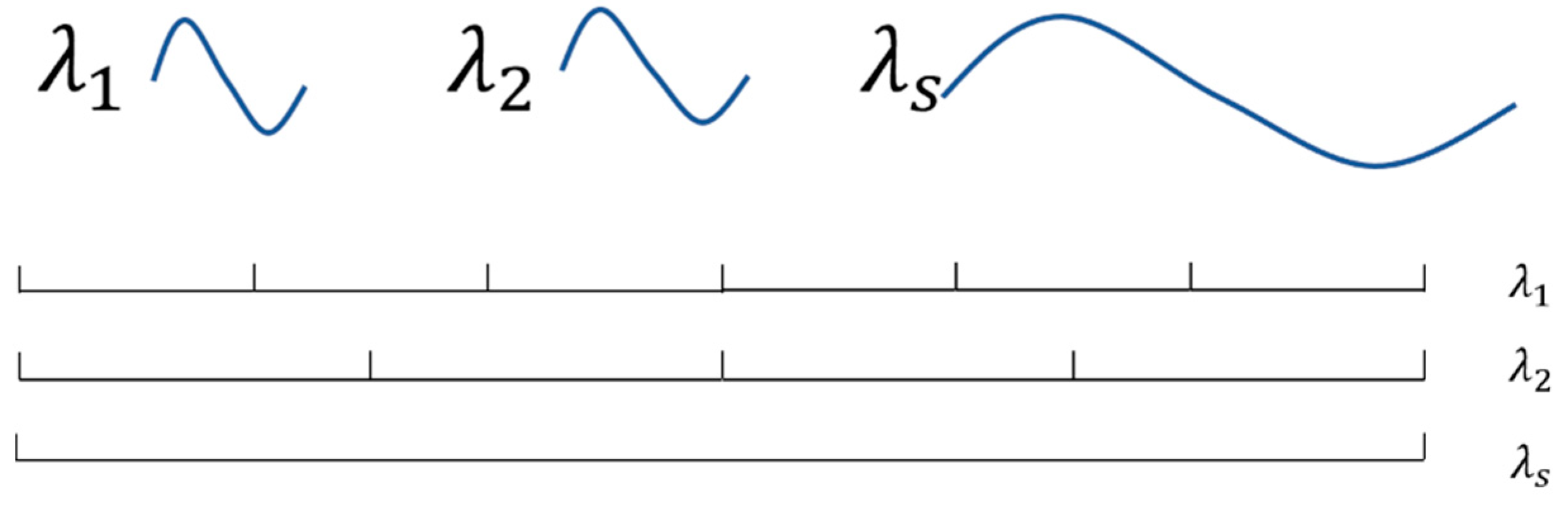
As shown in Figure 1, we define the synthetic wavelength λ s as:
λ s = 1 1 λ 1 1 λ 2 = λ 1 λ 2 λ 1 λ 2 ,
where λ 1 < λ 2 is assumed; when the difference between λ 1 and λ 2 is significantly small, the synthetic wavelength λ s is sufficiently large to guarantee that the piston error between the segments is lesser than λ s / 2 .
Both equations of Equation (8) were multiplied by 1 λ , and then, the second equation was subtracted from the first equation.
ω ( x , y ) ( 1 λ 1 1 λ 2 ) = ω ( x , y ) ( 1 λ s ) = φ 1 ( x , y ) φ 2 ( x , y ) 4 π + m 1 ( x , y ) m 2 ( x , y ) 2 ,
or
ω ( x , y ) = φ 1 ( x , y ) φ 2 ( x , y ) 2 k s + ( m 1 ( x , y ) m 2 ( x , y ) ) × λ s 2 ,
Equation (10) is similar to Equation (7), which means that ω ( x , y , λ s ) can be unwrapped with no ambiguity in the difference between the two wavelengths if the synthetic wavelength λ s is significantly large.
If the measurement errors (system error, environmental interference, detector noise, etc.) are considered, using the largest synthetic wavelength λ s to measure all piston errors is not a wise choice because the synthetic wavelength method leads to increased measurement errors. Therefore, we used a continuously tunable laser as the interference light source to obtain an adjustable measurement range. A suitable range that is slightly larger than the piston error can achieve the best detection precision.

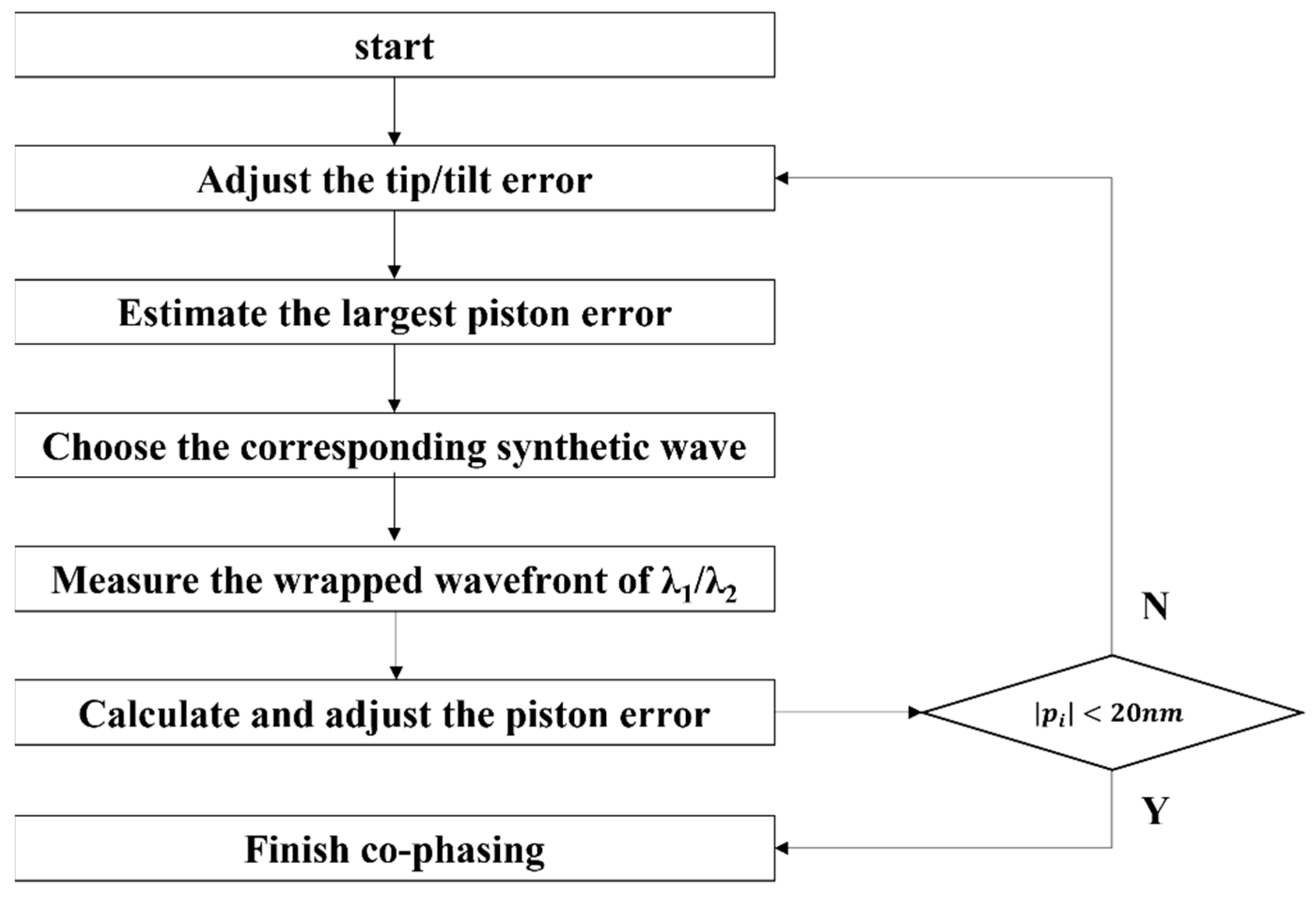
2.3. Co-Phasing by MPI Method

The profile function ω ( x , y ) in the segmented mirrors with no aberration but co-phasing error can be expressed as:
ω ( x , y ) = i = 1 N C i ( x x i cos   t x i , y y i cos   t y i ) ( 1 + ( x x i ) tan   t x i + ( y y i ) tan   t y i + p i ) ,
C i ( x , y ) = { 1 w i t h i n   p u p i l 0 e l s e ,
where C i ( x , y ) is the pupil function of each segment, x i and y i are the center coordinates of each segment, and ( t x i , t y i , p i ) are the tip/tilt and piston errors for each segment, respectively. N is the number of segments.
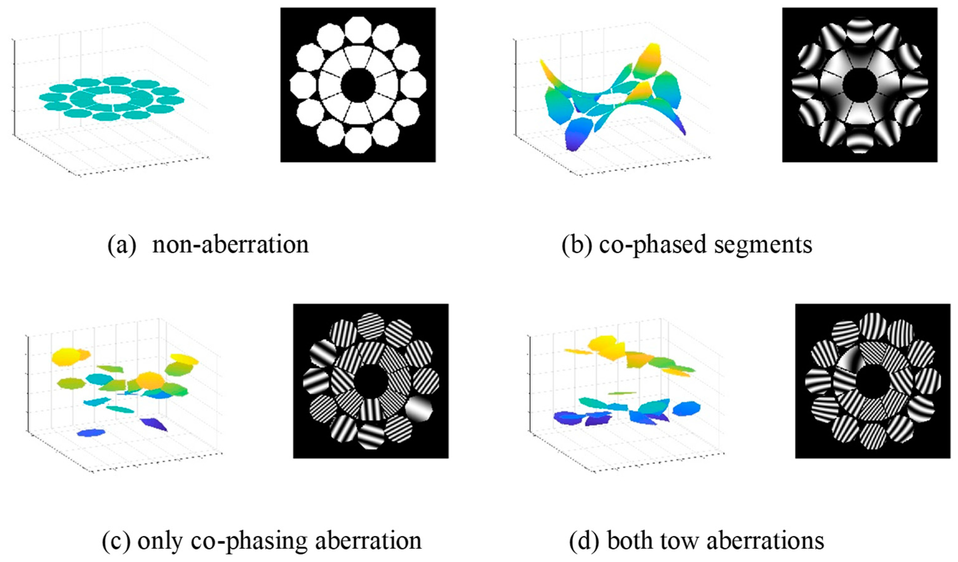
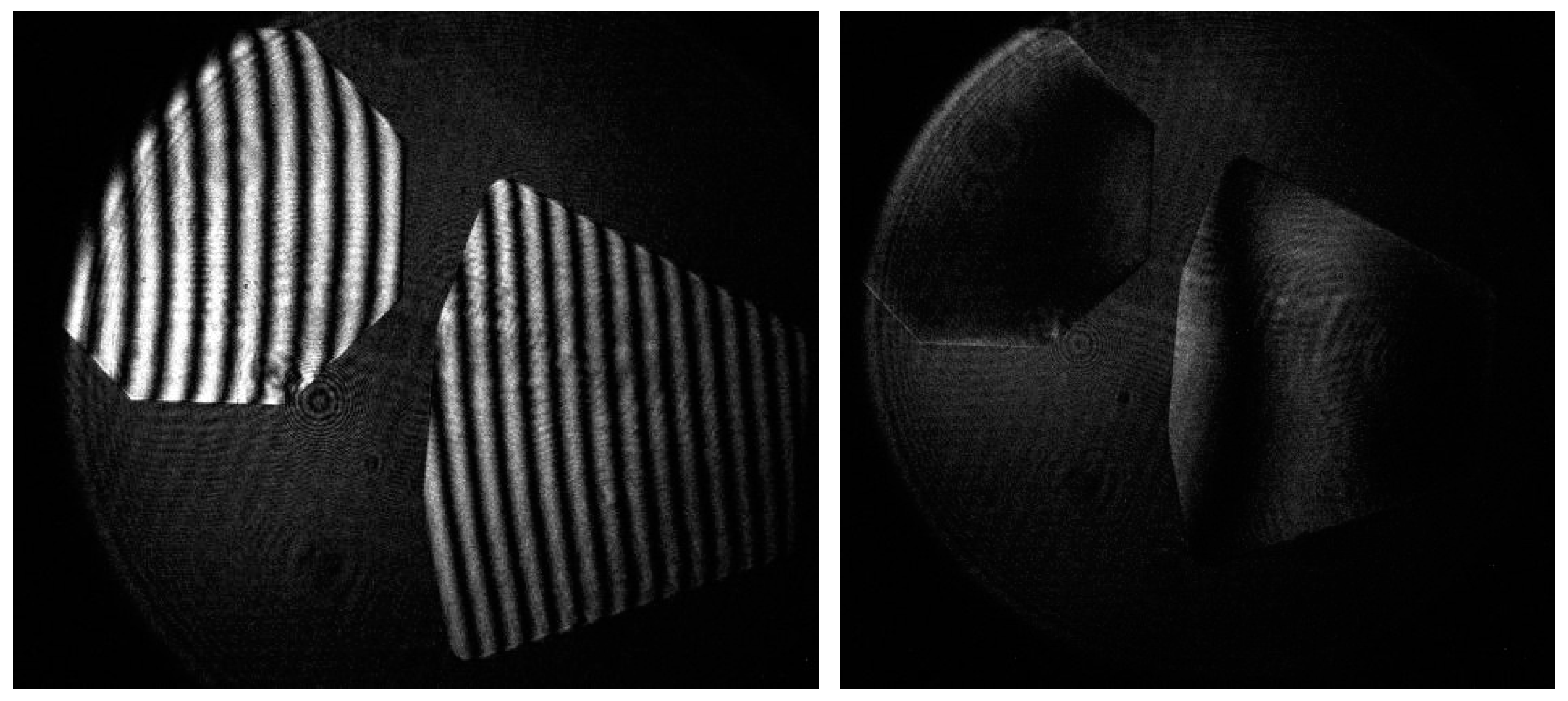
It should be noted that for the interference null-test when no aberration is assumed, the wavefront functions of spherical or aspherical mirrors become a perfect plane and no interference fringe appears, as shown in Figure 2. In this study, the segmented mirror system was formed by combining fan-shaped and octangle-shaped mirrors, and the geometrical shape of the segments was designed for the convenience of the unfolding process.
Figure 2. Simulated image of the profile function ω ( x , y ) , (a) with no aberration, (b) with system aberration of RMS = 240 nm in the case of segments, (c) with co-phasing aberration, piston < 0.01 mm and tip/tilt < 0.01 rad, and (d) with both aberrations of (b,c).
Photonics 09 00694 g002
Based on the phase-shifting and multiwavelength methods previously discussed, the profile function ω ( x , y ) expressed by Equation (11) can be calculated. A mask with several holes was applied to limit the pupil function C i ( x , y ) as a circle for the requirement of using Zernike polynomial to fit the wavefront.
The profile function ω ( x , y ) contains the information of the co-phasing error required to calculate the tip/tilt errors. Differentiating x and y on both sides of Equation (11) respectively, we obtain the expressions:
ω ( x , y ) x = i = 1 N C i ( x x i cos   t x i , y y i cos   t y i ) tan   t x i ,
and
ω ( x , y ) y = i = 1 N C i ( x x i cos t x i , y y i cos t y i ) tan t y i
During the experiment, the tip/tilt errors were calculated by the weighted average of least squares, fitting value by each line data in the mask.
The piston error can be obtained by calculating the average value of each data in the mask, considering the hypothesis that the mask center point is also the rotation center of each segment. However, in the common case, this assumption is not tenable, and the tip/tilt errors affect the result of the piston error; therefore, during experiments, the piston error is usually detected after the tip/tilt errors are adjusted to a small value.
p i = C i ( x x i , y y i )   ·   ω ( x , y ) C i ( x x i , y y i ) ,
where the tip/tilt errors are assumed to tend to zero, and p i is the piston error of the segment i . It should be noted that the only concerned result is the difference between the segments but not the absolute value of each p i .

3. Simulation

To explore the capability of the MPI method to co-phase the segmented mirror, extensive numerical simulations were performed. The geometrical shape and the mask of the segments in the simulation are shown in Figure 2, while the basic data for the simulation setup are provided in Table 1.

3.1. Multiwavelength Multistage Dynamic Adjustment Strategy

In the case of synthetic wavelength, the measurement error can be magnified at a direct ratio when the measure range is extended, as shown in Figure 3. Using exclusively the largest measurement range is not a good decision. Therefore, two changeable wavelengths were selected to match the existing co-phasing error. The desired situation is a measurement range, which is equal to a quarter of the synthetic wavelength that can adequately measure the largest co-phasing error in the segmented mirrors.
However, the true value of the co-phasing error is usually ambiguous, and there are constraints on the wavelength choice from laser technology; therefore, in this study, some stable wavelengths were used to build a multistage detection system, as shown in Table 2.

3.2. Numerical Simulations

To verify the ability and precision of the MPI method, a series of numerical simulations were performed, as shown in Figure 4. The contrast value γ was set to 1, the original input piston error and tip/tilt error were randomly generated, and the absolute value was less than 1 µm and 5 µrad respectively. Based on the principle that the relative position information of each segment is only concerned, we selected Segment 1 as the reference mirror. It should be noted that the piston error in this study was defined as the relative position difference in the z-direction between other segments and Segment 1.
When the signal–noise ratio (SNR) was assumed to be 20 dB, as shown in Figure 4a, for all the 20 segments, the RMS of the residual piston was 2.46 nm, and that of the residual tip/tilt was 5.06 nrad. The higher noise is introduced in Figure 4b; in the case that SNR was assumed to be 14 dB, the RMS of the residual piston increased to 6.34 nm, and that of the residual tip/tilt increased to 28.4 nrad. In the case of Figure 4c, the influence of the contrast ratio γ is considered; when γ = 0.2 and SNR = 20 dB, the RMS of the residual piston was 12.9 nm, and that of the residual tip/tilt was 58.1 nrad. The results of the numerical simulations indicated that even in a situation with a high noise and low contrast ratio, the MPI method could still maintain a satisfactory measurement precision. For our system, the piston error should be less than 50 nm and the tip/tilt error should be less than 100 nrad. Furthermore, in the case of the dynamic adjustment strategy, when the existing piston error was sufficiently small, the monochromatic wave interference, which has a better detection precision than the multiwavelength method, could be used.
The simulation result shown in Figure 4 only introduced a small piston error, and it was assumed that the laser wavelength is precise. For simulating a more practical result, we also set | Δ p i | 1   mm , and the measured wave had a ±0.03 nm deviation; meanwhile, a lower SNR (~10 dB) was assumed. The results are shown in Figure 5; the RMS of the residual piston error was 85.3 μm, and the precision of the laser source will significantly influence the detected precision when the synthetics wavelength is large. However, this precision in the result is still small enough to ensure the piston error can be converted to the next stage in Table 2.

4. Experimental Implementation and Discussion

4.1. Experimental Setup

The experimental setup is shown in Figure 6. We used two spherical mirrors to constitute a segmented mirror system which has a 400 mm-equivalent aperture and can be observed in Figure 6. Each spherical mirror has a significantly high surface precision (rms < 1/50λ), and, therefore, the mirror surface error can be neglected. Considering that the curvature difference of each mirror affects the co-phasing errors, these three segmented mirrors were cut from the same spherical mirror, its curvature radius was 1500 mm, and, therefore, the curvature consistency can be assured. The test tower’s size was 2256 mm × 980 mm × 980 mm, and the material was aluminum alloy.
Laser 1 was acquired from Sacher Lasertechnik Company, Germany; its wavelength is 632.8 nm. Laser 2 is a tunable laser TLB-6800-LN acquired from the New Focus Company of America; the wavelength range is 640–675 nm. The interference system is a Fizeau-interferometer fabricated by the Institute of Optics and Electronics and Shanghai Institute of Technical Physics, Chinese Academy of Sciences; this interferometer’s performance parameters can be seen in Table 3.
The flow chart of the experiment is shown in Figure 7. During the co-phasing process, the tip/tilt errors of each segment were first adjusted to approximately zero (can be observed in Figure 8). As the information of the tip/tilt errors in the wavefront data are continuous, only a single wave can be used to measure it. Then, depending on the largest piston errors for each segment, the required measurement range for the MPI can be determined. Subsequently, the two working waves of the tunable laser were affirmed and the wrapped wavefront data of each wave were measured by the Fizeau-interferometer. Then, each datum was averaged a sufficient number of times to decrease the random noise, and the piston error could be calculated and adjusted.

4.2. Experimental Result and Discussion

The experiments introduced in Section 4.1 were conducted. Different piston errors were introduced in one segmented mirror. First, we adjusted the segmented mirror system to make them nearly co-phased; then, different displacement values of z-axis (1 mm, 500 μm, 100 μm, and 10 μm) were added by a 6-DOF parallel platform, which was fabricated by PI company, and its positioning accuracy is 100 nm.

4.2.1. Dual-Wavelength Plan

The reason for using a tunable laser rather than two fixed wavelength lasers as the light sources is that the synthetic wavelength method increases the effect of the noise in the measurement, and as mentioned in Section 3.1, it appears to be a direct ratio relation. To verify this, some experiments were conducted.
The experimental result is shown in Figure 9. We used the 6-DOF parallel platform to add different displacements (1000, 500, and 100 μm) on the z-axis of a segmented mirror, and all the cases were measured by the synthetic wave of wavelength 4.41 mm; the measured deviations were 12.9, 105.9, and −65.3 μm, respectively. However, the largest deviation when the 4.41 mm synthetics wavelength was used could be more than 100 μm; this result is very different from the simulation results shown in Figure 3, in which the detection deviation was expected to be about 2 μm. The reason is that, for the experiment case, several factors will decrease the precision of detection. For example, the detection environment influence (vibration and air disturbance), the precision of laser source wavelength, different contrast ratios and power between the two detected wavelengths, and the extra error owing to the two wavelengths not being detected at the same time.
The experimental result shows that the detection precision will have the same statistical variation when the same synthetics wavelength is used, which can be about ±100 μm as shown in Figure 9; however, this precision is acceptable for the 1 mm piston error since it can successfully be converted to the next level in Table 2, and for the 500 and 100 μm piston error, it is not a acceptable result. This indicates that if the synthetic wave is significantly larger than the piston error, the measurement result cannot be converted owing to the noise, i.e., the use of only one unchanged synthetic wavelength cannot satisfy both the requirements of co-phasing detection: high precision (~50 nm) and large detection range (~1 mm). Therefore, a tunable laser was used to apply more synthetic waves, and the adjustment of the piston error can become a dynamic convergence process.

4.2.2. Multiwavelength Measurement: Coarse Phasing

The multiwavelength measurement results of coarse phasing stage are shown in Figure 10. Three different displacements were added on the z-axis to one segmented mirror (1 mm, 500 μm, and 100 μm). These piston errors were measured by the synthetic waves: 4.41 mm, 2.59 mm, and 603.87 μm, and the deviations were 26.56, 2.72, and 1.22 μm, respectively.
Coarse phasing measurement can achieve a satisfactory measurement precision if the synthetic wave is suitable for the piston error, and the RMS of the result is optimized as the synthetic wave is smaller. For the MPI, the major task is guaranteeing that the piston error can gradually decrease, and finally the piston error is smaller than a quarter of the monochromatic wave. Then, the piston error can be measured with no ambiguity.

4.2.3. Multiwavelength Measurement: Fine Phasing

After coarse phasing, the existing piston error decreases to dozens of micrometers or a few micrometers. Therefore, the synthetic wave should become smaller. In this study, the synthetic wave in fine phasing stage was adjusted to approximately 200 μm, and four piston errors were introduced, as shown in Figure 11. In the fine phasing stage, all the median measurement deviations were smaller than a quarter of a single wavelength, which means that the piston error could be successfully adjusted to the detection range of single wavelength interference, and for the single wave detection, the precision achieved was 1.2 nm. Finally, the wavefront image after co-phasing is shown in Figure 12.

5. Discussion

The result of Section 4 indicates that the MPI method can successfully co-phase the segmented mirrors even though the original piston error was set to a large number (~1 mm). The practical detection precision for piston could finally achieve 1.2 nm when the single wavelength was used to detect the piston within [−1/2λ, 1/2λ]. In comparison, the broad band Shake−Harman method’s capture range was 100 μm [9] and its precision was 26 nm, and the capture ranges of the DHS and DFS methods for the JWST’s coarse phasing were 100 and 300 μm respectively [15].
Although the interference method still has some problems for application in engineering practice, for example, it is hard to illuminate a large aperture at its center of curvature, and for the aspherical mirror, to modulate the spherical wave to an aspherical wave, a Computer-Generated Hologram (CGH) or a compensation lens group is required; the MPI method is still a valuable method for the segment co-phasing, owing to the large capture range and the high precision.

6. Conclusions

In this study, we introduced the MPI method to measure the co-phasing errors of segmented mirrors, aiming to solve large-piston-error detection problems, which usually occur when the space-based segmented mirrors undergo unfolding or are subject to certain accidents (such as small meteorite impact). The existing detection methods can hardly detect a piston error of more than 1 mm; therefore, this study aimed to detect a large range of piston errors with satisfactory precision.
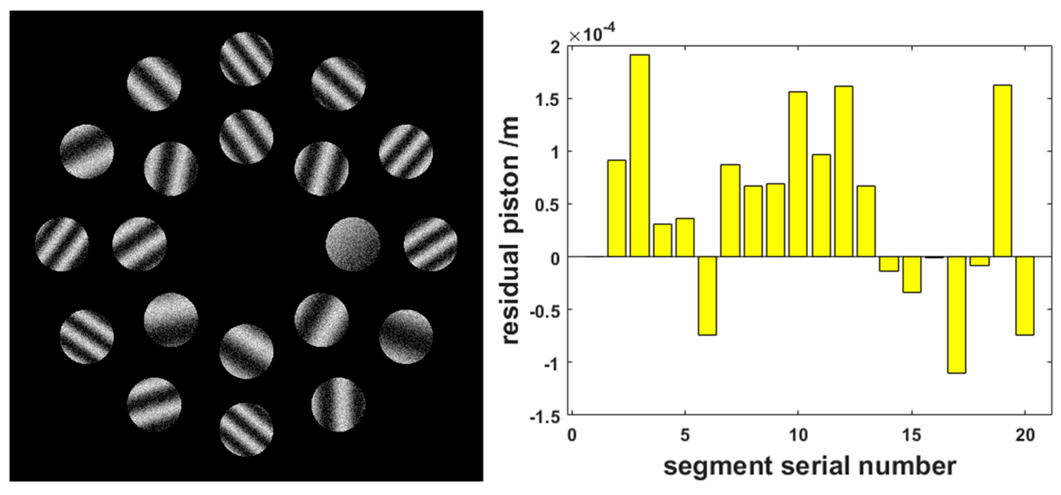
In the simulation, piston and tip/tilt errors were both added to a 20-segment system with noise, and the achieved detection precision of piston error was approximately 12.9 nm when SNR was 14 dB, and the contrast ratio was 0.2. Hence, the robustness of the MPI method was confirmed. In the experiment, two spherical segmented mirrors were applied (one of them was the reference mirror). The other mirror had a piston error of approximately 1 mm owing to the 6-DOF parallel platform. After the dynamic adjustment by the MPI method, the original piston was successfully adjusted to less than a quarter of a single wavelength, and in the monochromatic interference, the final detection precision of the piston was approximately 1.2 nm. Furthermore, owing to the dynamic adjustment strategy, the detection range obtained was greater than 5 mm.
The MPI method showed satisfactory potential for detection of the co-phasing errors of the segmented mirror, As this method has the advantages of simultaneous calculation of the tip/tilt and piston errors with high precision, large detection range, a relatively simple optical system and measurement process, and an individual light source without affecting the working time of the telescope, it is expected to have a significant impact on future research in the field of segmented mirrors, and should have possible applications in the fields of development of more powerful telescopes and space exploration.

Author Contributions

Conceptualization, Y.K.; methodology, R.Q.; formal analysis, R.Q. and Z.Y.; investigation, R.Q. and Z.Y.; resources, Y.L.; data curation, R.Q. and Z.Y.; writing-original draft preparation, R.Q.; writing-review and editing, R.Q.; visualization, R.Q.; supervision, Y.L.; project administration, Y.L.; funding acquisition, Y.L. All authors have read and agreed to the published version of the manuscript.

Funding

This research was funded by National Natural Science Foundation of China Major Project (42192582); National Key R&D Program of China(2016YFB0500400); Major Project of National High-Resolution Earth Observation System of China (A0106/1112).

Data Availability Statement

Data underlying the results presented in this paper are not publicly available at this time but may be obtained from the authors upon reasonable request.

Conflicts of Interest

The authors declare no conflict of interest.

References

  1. Yaitskova, N.; Dohlen, K.; Dierickx, P. Analytical study of diffraction effects in extremely large segmented telescopes. J. Opt. Soc. Am. A 2003, 20, 1563–1575. [Google Scholar] [CrossRef] [PubMed]
  2. Yaitskova, N.; Dohlen, K. Tip-tilt error for extremely large segmented telescopes: Detailed theoretical point-spread-function analysis and numerical simulation results. J. Opt. Soc. Am. A 2002, 19, 1274–1285. [Google Scholar] [CrossRef]
  3. Chanan, G.; Troy, M. Strehl ratio and modulation transfer function for segmented mirror telescopes as functions of segment phase error. Appl. Opt. 1999, 38, 6642–6647. [Google Scholar] [CrossRef] [PubMed]
  4. Chanan, G.; Schoeck, M.; Troy, M. Approach based on χ2 to phasing segmented-mirror telescopes using multiple wavelengths: Data reduction, wavelength selection, capture range. Appl. Opt. 2022, 61, 935–944. [Google Scholar] [CrossRef] [PubMed]
  5. Rouze, B.; Primot, J.; Lanzoni, P.; Zamkotsian, F.; Tache, F.; Bellanger, C. High-dynamic range segmented mirror metrology by two-wavelength PISTIL interferometry: Demonstration and performance. Opt. Express 2020, 28, 32415–32425. [Google Scholar] [CrossRef] [PubMed]
  6. Yang, L.; Yang, D.; Yang, Z.; Liu, Z. Co-phase state detection for segmented mirrors by dual-wavelength optical vortex phase-shifting interferometry. Opt. Express 2022, 30, 14088. [Google Scholar] [CrossRef] [PubMed]
  7. Cheng, Y.-Y.; Wyant, J.C. Two-wavelength phase shifting interferometry. Appl. Opt. 1984, 23, 4539–4543. [Google Scholar] [CrossRef] [PubMed]
  8. Cheng, Y.-Y.; Wyant, J.C. Multiple-wavelength phase-shifting interferometry. Appl. Opt. 1985, 24, 804–807. [Google Scholar] [CrossRef] [PubMed]
  9. Shi, F.; Redding, D.C.; Lowman, A.E.; Ohara, C.M.; Burns, L.A.; Petrone, P., III; Bowers, C.W.; Basinger, A.S. Segmented mirror coarse phasing with white light interferometry: Modeling and experimenting on NGST’s wavefront control testbed. In Proceedings of the SPIE 4850, IR Space Telescopes and Instruments, Waikoloa, HI, USA, 5 March 2003. [Google Scholar]
  10. Wilhelm, R.; Luong, B.; Courteville, A.; Estival, S.; Gonté, F. Optical phasing of a segmented mirror with sub-nanometer precision: Experimental results of the APE Internal Metrology. In Proceedings of the Ground-Based and Airborne Telescopes II, Marseille, France, 23–28 June 2008; Volume 7012, pp. 412–423. [Google Scholar]
  11. Li, B.; Yu, W.H.; Chen, M.; Tang, J.L.; Xian, H. Co-phasing experiment of a segmented mirror using a combined broadband and two-wavelength algorithm. Appl. Opt. 2017, 56, 8871–8879. [Google Scholar] [CrossRef] [PubMed]
  12. Esposito, S.; Pinna, E.; Puglisi, A.; Tozzi, A.; Stefanini, P. Pyramid sensor for segmented mirror alignment. Opt. Lett. 2005, 30, 2572–2574. [Google Scholar] [CrossRef]
  13. Van Dam, M.A.; McLeod, B.A.; Bouchez, A.H. Dispersed fringe sensor for the Giant Magellan Telescope. Appl. Opt. 2016, 55, 539–547. [Google Scholar] [CrossRef]
  14. Guerra-Ramos, D.; Díaz-García, L.; Trujillo-Sevilla, J.; Rodríguez-Ramos, J.M. Piston alignment of segmented optical mirrors via convolutional neural networks. Opt. Lett. 2018, 43, 4264–4267. [Google Scholar] [CrossRef]
  15. Zhao, W.; Wang, H.; Zhang, L.; Gu, Y.; Zhao, Y. Piston detection in segmented telescopes via multiple neural networks coordination of feature-enhanced images. Opt. Commun. 2021, 507, 127617. [Google Scholar] [CrossRef]
  16. Guerra-Ramos, D.; Trujillo-Sevilla, J.; Rodríguez-Ramos, J.M. Towards Piston Fine Tuning of Segmented Mirrors through Reinforcement Learning. Appl. Sci. 2020, 10, 3207. [Google Scholar] [CrossRef]
  17. Shi, F.; King, B.M.; Sigrist, N.; Basinger, S.A. NIRCam Long Wavelength Channel grisms as the Dispersed Fringe Sensor for JWST segment mirror coarse phasing. In Proceedings of the Space Telescopes and Instrumentation 2008: Optical, Infrared, and Millimeter, Marseille, France, 23–28 June 2008; Volume 7010, pp. 691–704. [Google Scholar] [CrossRef]
Figure 1. Synthetic wave schematic diagram.
Photonics 09 00694 g001
Figure 3. Effect of synthetic wavelength to measure the error. The x-axis denotes the length of the synthetic wave, the y-axis denotes the RMS of the residual piston error for the 20 simulated segments, the blue line sets the SNR to 20 dB with a piston error | Δ p i | 0.01 mm for each segment, and the red line sets the SNR to 40 dB.
Photonics 09 00694 g003
Figure 4. Simulation results with a random co-phasing error | Δ p i | 1   μ m , | Δ t x i | 5   μ r a d , | Δ t y i | 5   μ r a d ; the synthesis wavelength is 10.55 μm (630 and 670 nm, respectively), (a) left is the residual between the real piston and measurement piston for all segmented mirrors, and right is the residual of the tip error (blue bar) and tilt error (red bar); (a,b) are in different SNRs, and (c) is the situation when the contrast ratio is low.
Photonics 09 00694 g004
Figure 5. Simulation results with a random co-phasing error | Δ p i | 1   mm , | Δ t x i | 5   μ rad , | Δ t y i | 5   μ rad ; the synthesis wavelength is 5170 μm (642.8 and 642.88 nm, respectively),left is the interference fringe in 642.8 nm, and right is the residual between the real piston and measurement piston for all segmented mirrors.
Photonics 09 00694 g005
Figure 6. Experimental setup: the laser source and Fizeau-interferometer were placed at the top of the frame, the segmented mirrors and adjustment equipment were placed at the bottom, all of them were on the optical platform, and the entire system size was approximately 2.5 × 0.9 × 0.9 m.
Photonics 09 00694 g006
Figure 7. Flowchart of the experiment.
Photonics 09 00694 g007
Figure 8. Interference fringe of the original case (left), and nearly similar tip/tilt (right).
Photonics 09 00694 g008
Figure 9. Boxplot of the deviations of the measurement results (4.41 mm).
Photonics 09 00694 g009
Figure 10. Boxplot of the deviations of the measurement results (coarse phasing).
Photonics 09 00694 g010
Figure 11. Boxplot of the deviations of the measurement results (fine phasing).
Photonics 09 00694 g011
Figure 12. Wavefront of two segments in 663.77 nm (after fine co-phasing).
Photonics 09 00694 g012
Table 1. Specifications used for the simulations.
ParameterValue
Number of segments20
Range of the tunable laser630–670 nm
Resolution of the tunable laser0.01 nm
CCD pixel1000 × 1000
Table 2. Multistage synthetic wavelength strategy.
Wave 1 (nm)
λ 1
Wave 2 (nm)
λ 2
Synthetic Wave (μm)
λ s
Estimated Piston (μm)
p i
642.81642.841,3201000~10,000
642.88642.85170500~1000
642.96642.82580100~500
643.6642.8517.1310~100
652642.845.561~10
67063010.550.10~1
630<0.1
Table 3. Performance parameters of the Fizeau-interferometer.
ParameterValue
Measure precisionRMS < 0.001λ
Effective working distanceL > 50 m
Pupil magnification1
CCD pixel1000 × 1000
Aperture10 mm
Size780 mm × 400 mm × 350 mm
Operating temperature15~26 °C
Weight<45 kg
Power consumption<750 W
Publisher’s Note: MDPI stays neutral with regard to jurisdictional claims in published maps and institutional affiliations.

