Communication

Optical Design of a 4× Zoom Lens with a Stable External Entrance Pupil and Internal Stop

1
Xi’an Institute of Optics and Precision Mechanics, Chinese Academy of Sciences, Xi’an 710119, China
2
University of Chinese Academy of Sciences, Beijing 100049, China
*
Author to whom correspondence should be addressed.
Photonics 2022, 9(3), 191; https://doi.org/10.3390/photonics9030191
Submission received: 20 February 2022 / Revised: 9 March 2022 / Accepted: 15 March 2022 / Published: 17 March 2022
(This article belongs to the Special Issue Optical Instrumentation)

Abstract

:
Zoom lens with stationary external entrance pupil and internal stop is a type of special optical system that can be used in cascaded optics to meet the requirements of long focal length or variable magnification. We proposed a 4× zoom lens to improve the pupil walking limitation observed in the conventional design. Varifocal- and pupil-stable differential equations are presented and a paraxial design of the lens with two moving parts was developed. Moreover, the zoom lens, which functions in the visible waveband 500 nm~750 nm, is designed using seven types of common optical glasses, has a constant f-number of 10 and focal range of 100 mm~400 mm, and achieves pupil walking in the range −3.9 mm to +4.3 mm. The results demonstrate that the design had good image quality and tolerance characteristics. Owing to the limited pupil walking and zoom capability, the scheme is of considerable interest for application in electrical optical systems.

1. Introduction

A zoom lens with an external pupil is a special optical system that can be used in cascaded optics to achieve a long focal length or variable magnification [1]. An externally located entrance pupil is a necessary component in these systems to match the scanning elements (typically fast steering mirror) or cascaded systems with reflective or catadioptric optics in front of the imaging objective [2,3]. This results in a major limitation: the pupil location varies over the entire zoom range [4] (i.e., the pupil walking problem). An internal size-changeable aperture stop is also required to maintain a constant f-number and stop size throughout the zoom journey and help with high light control. All these requirements demand a zoom lens with an external stable entrance pupil and an internally located stop.
Thus far, several structures and methods have been employed to realize this type of zoom lens. The possibility of such a zoom system was presented in 1965 by Wooters and Silvertooth [5]. Hopkins later proposed an analytical method to address this issue and patented a lens with three moving components [6,7]. Bystricky and Yoder reported a zoom system with a moving exit pupil and an external entrance pupil [8]. Yeh et al. described a grapho-analytical method for designing symmetrical structures of three-moving-parts zoom systems [9]. Kryszczyński then developed zoom structures without assuming any symmetry [10]. Novel devices and numerical methods have been employed to solve problems. For example, Mikš et al. described methods for designing non-moving-part zoom systems with tunable lenses [11,12,13,14,15]. Sourav and Lakshminarayan presented an evolutionary program for solving the problem of pupil stabilization using a two-coupled moving component variator and a third component compensator [16]. Song and Zhao investigated the optimal power distribution problem for minimizing pupil walking in afocal zoom lenses using MATLAB [4]. Yu and Wang introduced particle swarm optimization to fulfill the automatic design of a mid-wavelength infrared dual-conjugate zoom system [17].
The structures presented in the aforementioned papers had three independent or coupled moving components or exhibited large pupil walking. In this paper, we proposed a method to design a four-group two-moving-parts zoom lens with an external pupil and internal stop and improved the pupil walking limitations of the conventional design. A paraxial model with lens power and distance as parameters was established, as discussed in Section 2. The optical design process and details of the resulting objective are presented in Section 3, and the manufacturability and performance of the lens elements are discussed in Section 4. The conclusions are summarized in Section 5.

2. Paraxial Design

A mathematical model that describes the paraxial characteristics of the mentioned systems is proposed and discussed with the thin lens theory in this section [18].

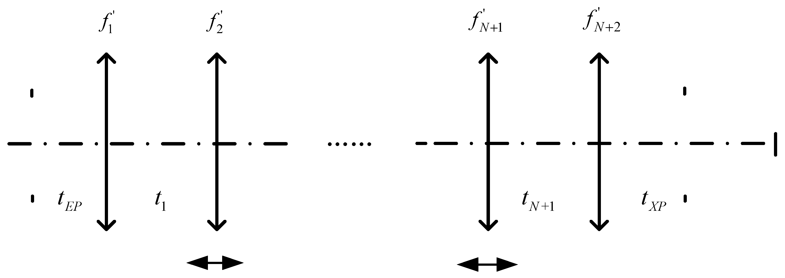
2.1. Varifocal Differential Equation (VDE)

In most cases, the zoom lens consists of N + 2 adjacent parts, as depicted in Figure 1. As the shift of the N moving elements make the system zoom, the image plane should be kept the same over the entire zoom range [19]. Mathematically, this means that the N moving elements and their locus should satisfy the varifocal differential equation, which is generally described as follows:
2 N + 1 1 m i 2 m i 2 f i d m i = 0 ,
where t E P and t X P denote the entrance and exit pupil distances; t i represents the distance between the i-th and i + 1-th element; and m i and f i denote the longitude magnification and focal length of the i-th element, respectively.
To realize an external stable pupil and internal fixed stop, a relay or intermediate image is required. Furthermore, inspired by [9,13], a pupil-stable differential equation (PSDE) specific to the issue of the stable pupil plane was derived in this study [10,19]. The PSDE can be written as follows:
2 N + 1 1 m i E P 2 m i E P 2 f i d m i E P = 0 ,
where m i E P is the longitude magnification of i-th element to the pupil distance.
The equation group has continuous solutions only when the lens has three or more moving groups, which coincides with H. H. Hopkins’ analysis. The distance between various lens groups can be acquired within a reasonable range using the above equations. Meanwhile, we could obtain the paraxial structure of the zoom lens.

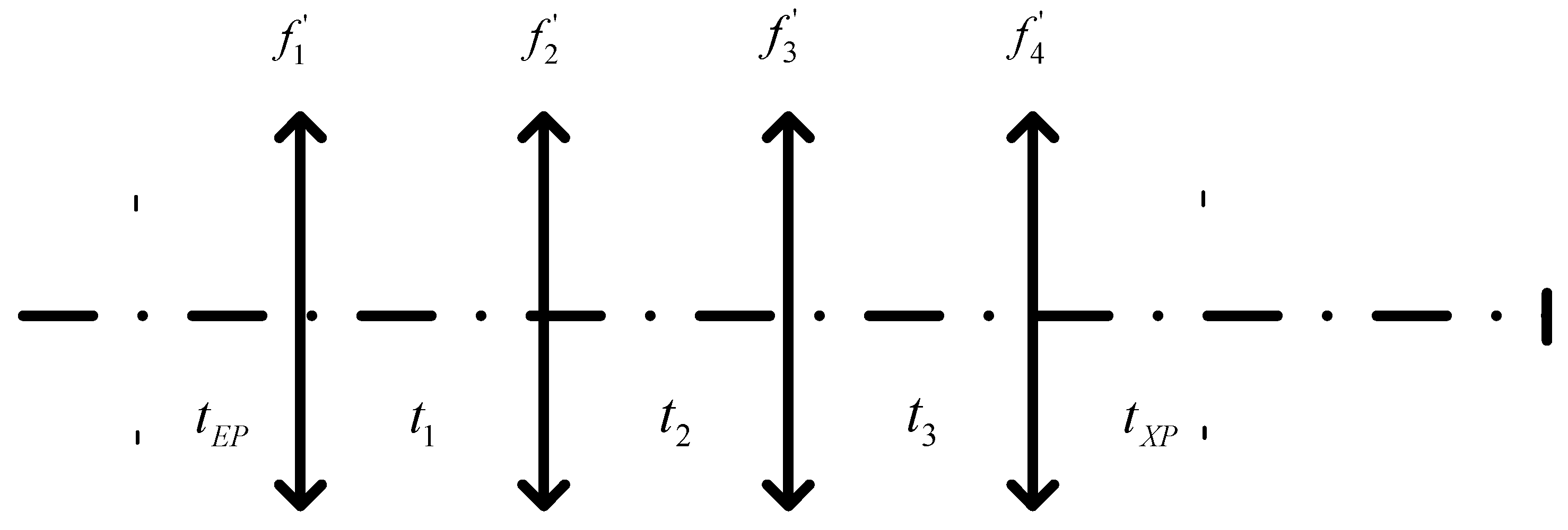
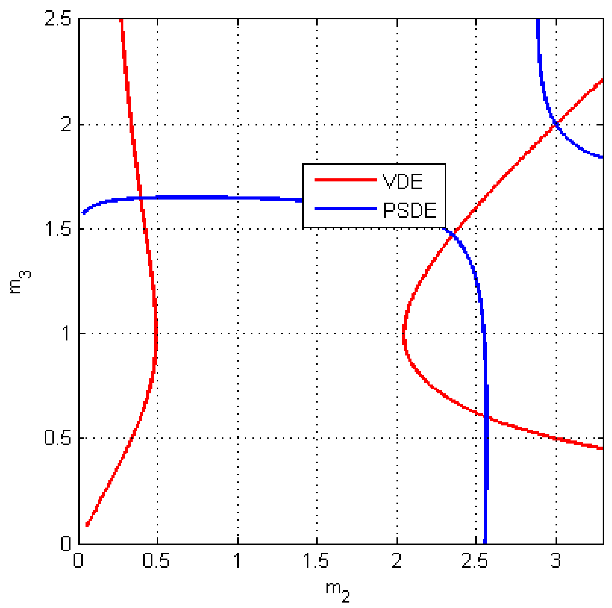
2.2. Two-Moving Parts Zoom Lens

The zoom lens, exhibiting the aforementioned characteristics, consists of two moving parts and is employed to provide more illustrations in this section. A typical paraxial lens structure is depicted in Figure 2, where f 1 ,   f 2 ,   f 3 , and f 4 denote the focal lengths of groups 1, 2, 3, and 4, respectively; and groups 2 and 3 are moving parts.
The image plane should remain the same throughout the zoom journey, so groups 2 and 3 needed to satisfy the varifocal differential equation:
1 m 2 2 m 2 2 f 2 d m 2 + 1 m 3 2 m 3 2 f 3 d m 3 = 0 ,
where m 2 and m 3 are the image longitude magnification of each group, which can be rewritten as m 2 = f 2 t 1 l 1 f 2 and m 3 = t 3 + l 4 f 3 f 3 . l 1 denotes the image distance of group 1 and l 4 is the object distance of group 4.
To maintain the pupil or stop location fixed over the entire zoom range, groups 2 and 3 needed to satisfy the PSDE:
1 m 2 E P 2 m 2 E P 2 f 2 d m 2 E P + 1 m 3 X P 2 m 3 X P 2 f 3 d m 3 X P = 0 ,
where m 2 E P and m 3 X P are the pupil longitude magnification of each group. Numerically,
m 2 E P = 1 1 m 2 f 1 2 f 2 ( t E P f 1 ) ,
m 3 X P = m 3 + f 4 2 t X P f 4 f 4 2 l 4 f 4 f 3 ,
If we set K 2 = f 1 2 f 2 ( t E P f 1 ) , K 3 = f 4 2 t X P f 4   f 4 2 l 4 f 4 f 3 , then
d m 2 E P = 1 ( 1 K 2 m 2 ) 2 d m 2 ,
d m 3 X P = d m 3 ,
After transforming, Equation (4) can be simplified as
f 2 m 2 2 d m 2 f 2 ( 1 K 2 m 2 ) 2 d m 2 + f 3 ( m 3 + K 3 ) 2 d m 3 f 3 d m 3 = 0 ,
Equations (3) and (9) can depict the two-moving-parts zoom lens with an external pupil and internal stop. According to these equations, we could obtain up to five solutions or zoom positions that can assure the fixed stop and entrance pupil. However, only solutions located on the same solutions’ curve of VDE could ensure the continuity of zooming. Additionally, the magnification value of the solutions should not be too large—empirically, not greater than 5—in order to avoid the lens structure becoming too complex. Once given the lens specifications such as focal length, zoom ratio, pupil distance, and other parameters, we could substitute them into the above equations and obtain the initial structure of the system. In addition, the solutions contributed to the stable pupil lens design in terms of merit function building.

3. Optical Design

The 4× zoom lens proposed in this paper is a part of a cascaded systems with afore set reflective optics. In this way, the entrance pupil of the proposed lens needed to meet or be in the vicinity of the exit pupil of the reflective optics to minimize vignetting, particularly in the wide field of view (FOV) position; further, an internal stop was required to help with the high light control.

3.1. Specifications

The design involved a high-performance complementary metal-oxide-semiconductor transistor (CMOS) image sensor with an effective area of 19.8 mm × 10.8 mm and a pixel size of 10 μm × 10 μm. An image height of 11 mm was used in the design process to reach a diagonal image size of 22 mm in total. The focal length range of the lens was 100 mm~400 mm and the f-number was 10. The overall length (from the entrance pupil to the image plane), back focal length, distortion, and modulation transfer function was specified to realize compact size and good image performance. Pupil walking was determined to be less than 10mm. Table 1 summarizes the specifications of the design.

3.2. Design and Optimization Process
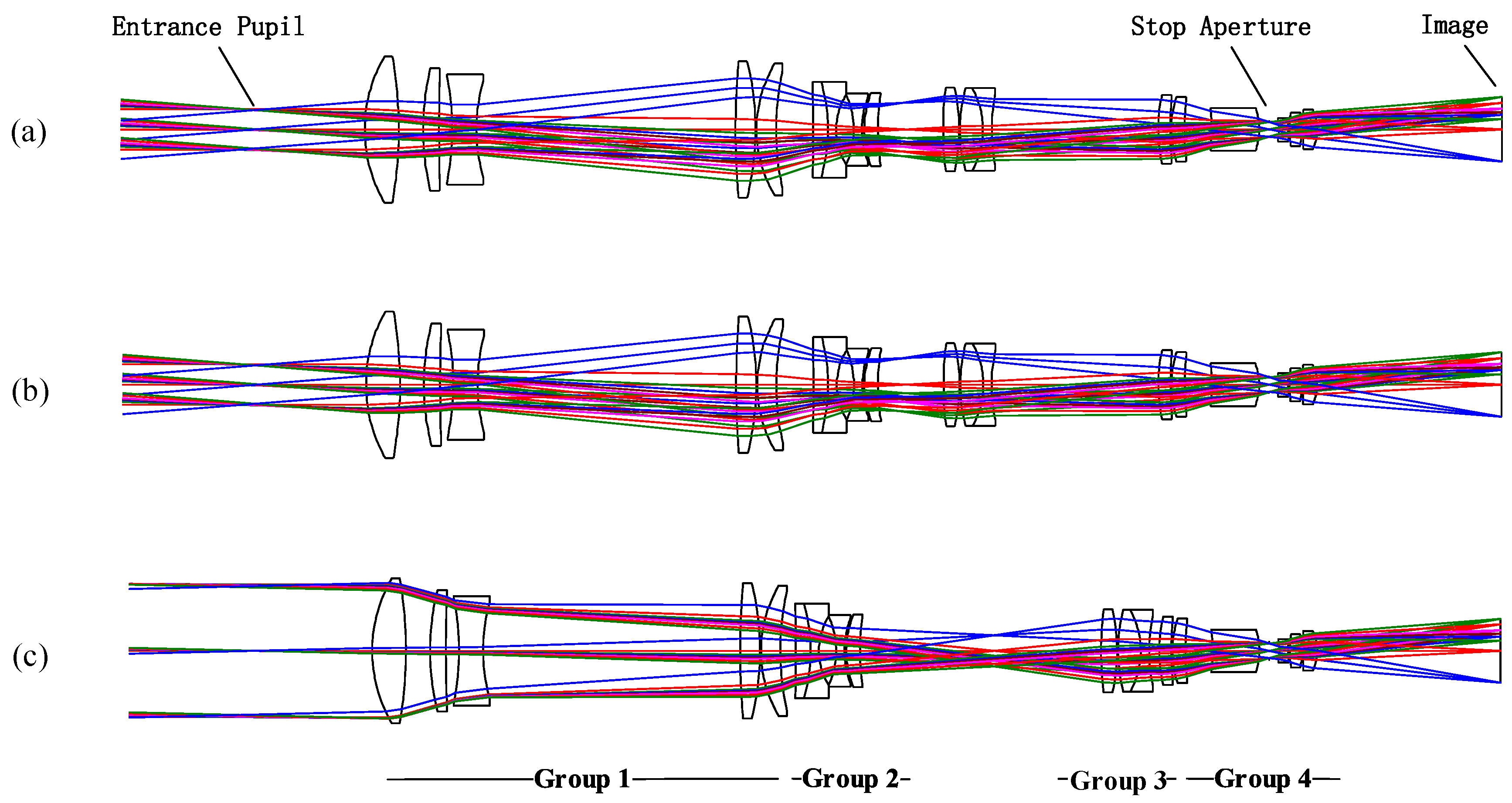
The zoom lens design was realized using Code V 11.0. As shown in Table 2, the initial lens structure which corresponds to a wide FOV (WFOV) and narrow FOV (NFOV), solved through the equations proposed in Section 2 using MATLAB, was inserted and optimized in two configurations. Only solutions with m2 > 2 were considered to fulfill a faster zoom speed. The total track, focal length, pupil location, and performance was constrained in the merit functions and the lens radius, thickness, air gap, and glass materials was optimized by default constraints. Once both configurations performed well, we turned to the second design stage. Three or more configurations were added in the design; the manufacturability and realizability constraints were added consecutively; and the maximum pupil distance was found and further optimized until the results met the performance requirements.
Some tips and tricks were employed during the optimizing process. According to Figure 3, there were up to four points that could keep the pupil remaining fixed in two-moving-part zoom lens and five configurations were needed in the design process. Using regional instead of weighted constraints of the focal length and considering pupil distance on middle FOVs helped with the pupil walking reduction; further, watch dogs were needed on the magnifications to avoid breakpoints in the moving paths of each component.

3.3. Design Results

Three different zoom positions of the resulting 4× zoom lens with a stable external entrance pupil and internal stop are illustrated in Figure 4. The zoom system comprises fourteen singlets and two cemented doublets, uses seven kinds of common optical glass materials, and has an overall length of 370 mm from the entrance pupil to the image plane. The largest clear aperture, which is located on the first component, had a diameter of 41 mm; a larger cement element with a semi-diameter of 14 mm was found in the first moving part. Table 3 summarizes the lens data for the resulting zoom lens. The surface No. 1 was set to be the entrance pupil.
We split the lens components into four groups, as shown in Figure 4. Lenses from surface 8 to 11 in Table 3 worked as a relay for the production of space for the folding mirror, and later, the moving part. In addition, both lenses used low-abbe-value materials to balance the lateral color induced by the front lens. When zooming forward or backward, the magnifications of groups two and three changed by approximately two to realize the 4× zoom range. In particular, group two had a negative power and employed a cement doublet with an HZLAF92 positive lens and an HFK95N negative lens. Further, group three had a negative power using a cement lens consisting of an HBAF3 positive lens and an HZF1 negative lens. Meanwhile, an intermediate image was formed between the two groups to help with the external stable pupil. Finally, an internal lens stop aperture was set in the center of group four to fulfill a fixed stop location and size in the zoom lens and help with the correction of the symmetrical aberrations.

4. Performance

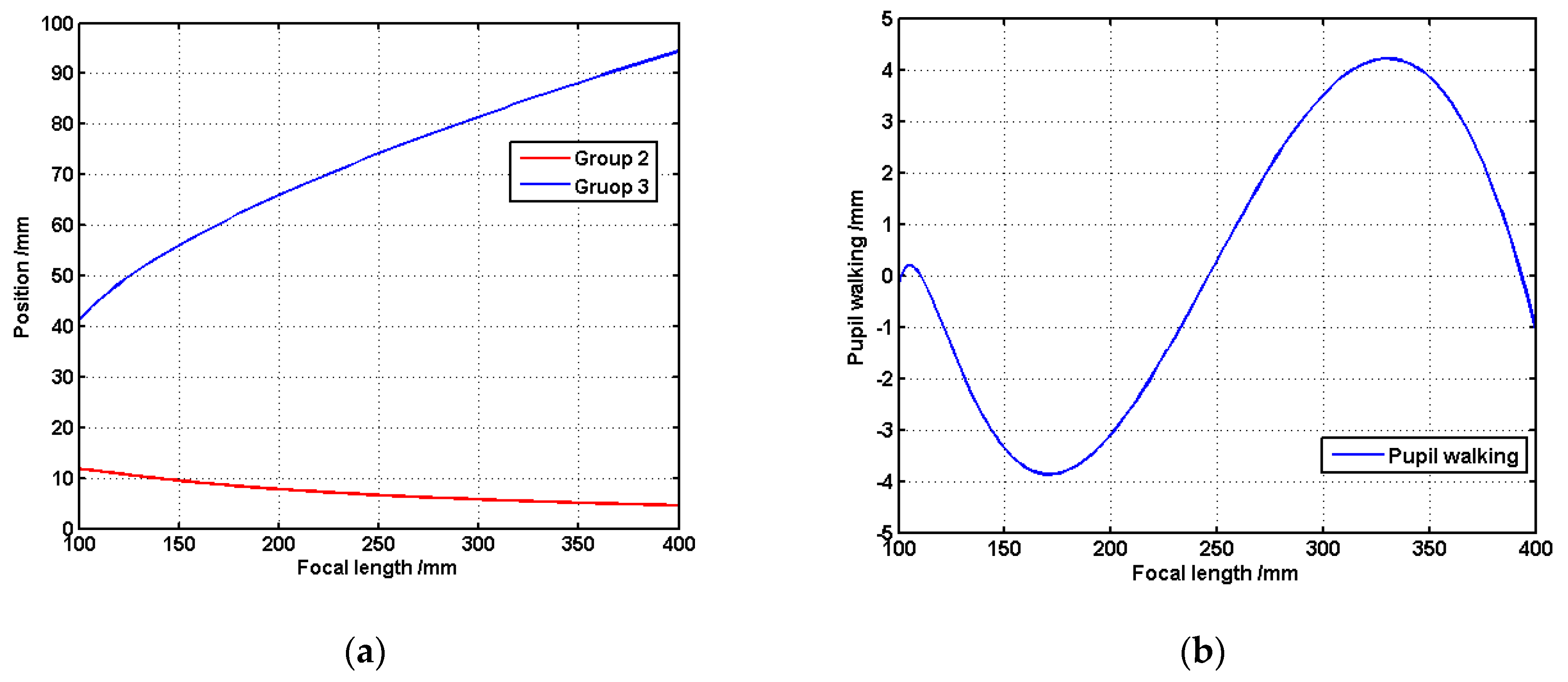
4.1. Cam Curve and Pupil Walking

To optimize the cam curve and inspect the pupil walking along the entire zoom range, we performed a macro program on Code V, and the results are shown in Figure 5a. The locus described the relationship between the lens positions and the focal length, and the smoothness and continuity of the curve were strongly related to engineering feasibility. An entrance pupil distance of 35 mm with walking in the range −3.9 to +4.3 mm is illustrated in Figure 5b, which depicts the changing of the pupil walking with the zoom of the focal length. The results also confirmed the feasibility of the method developed in Section 2.

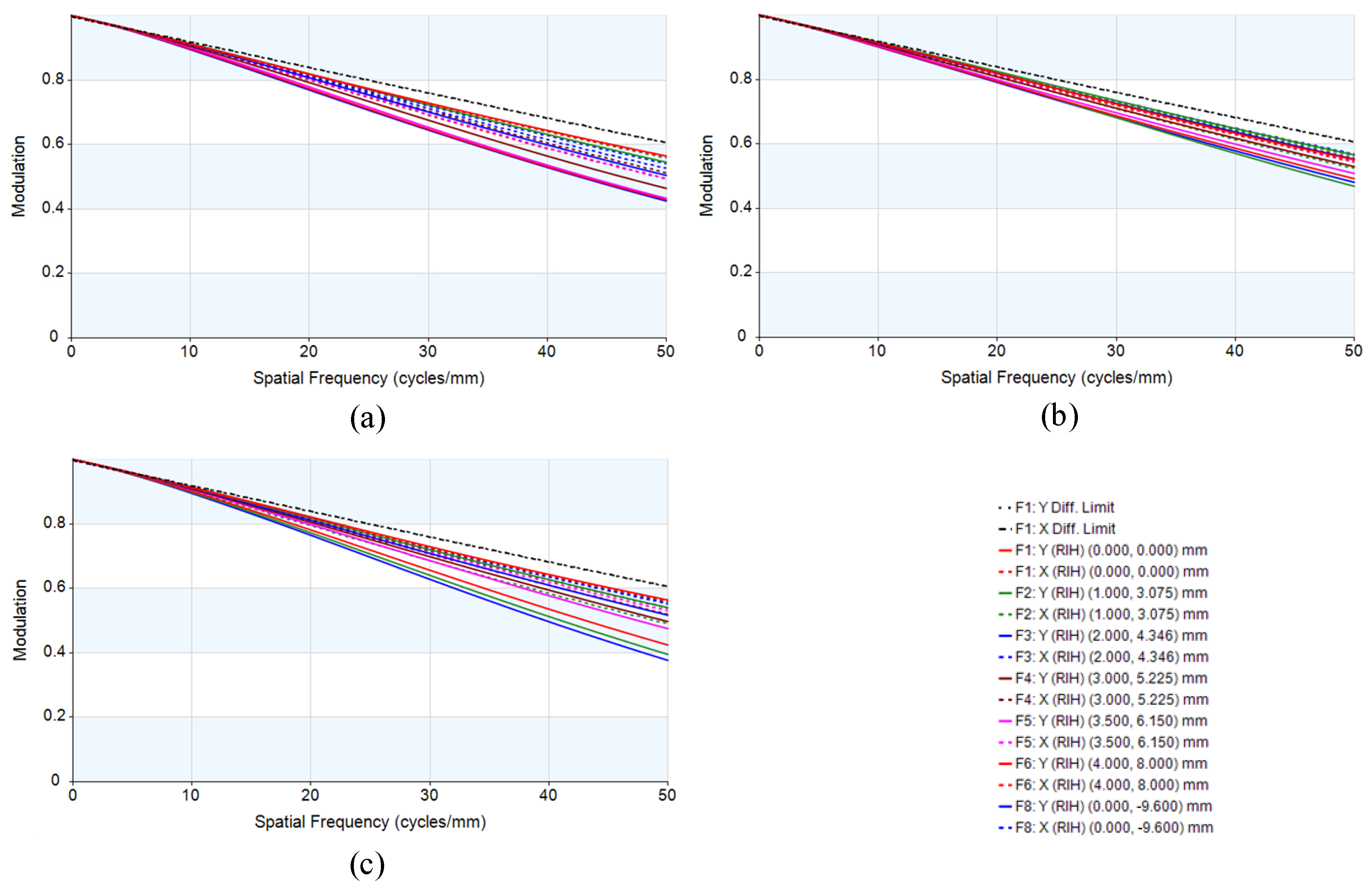
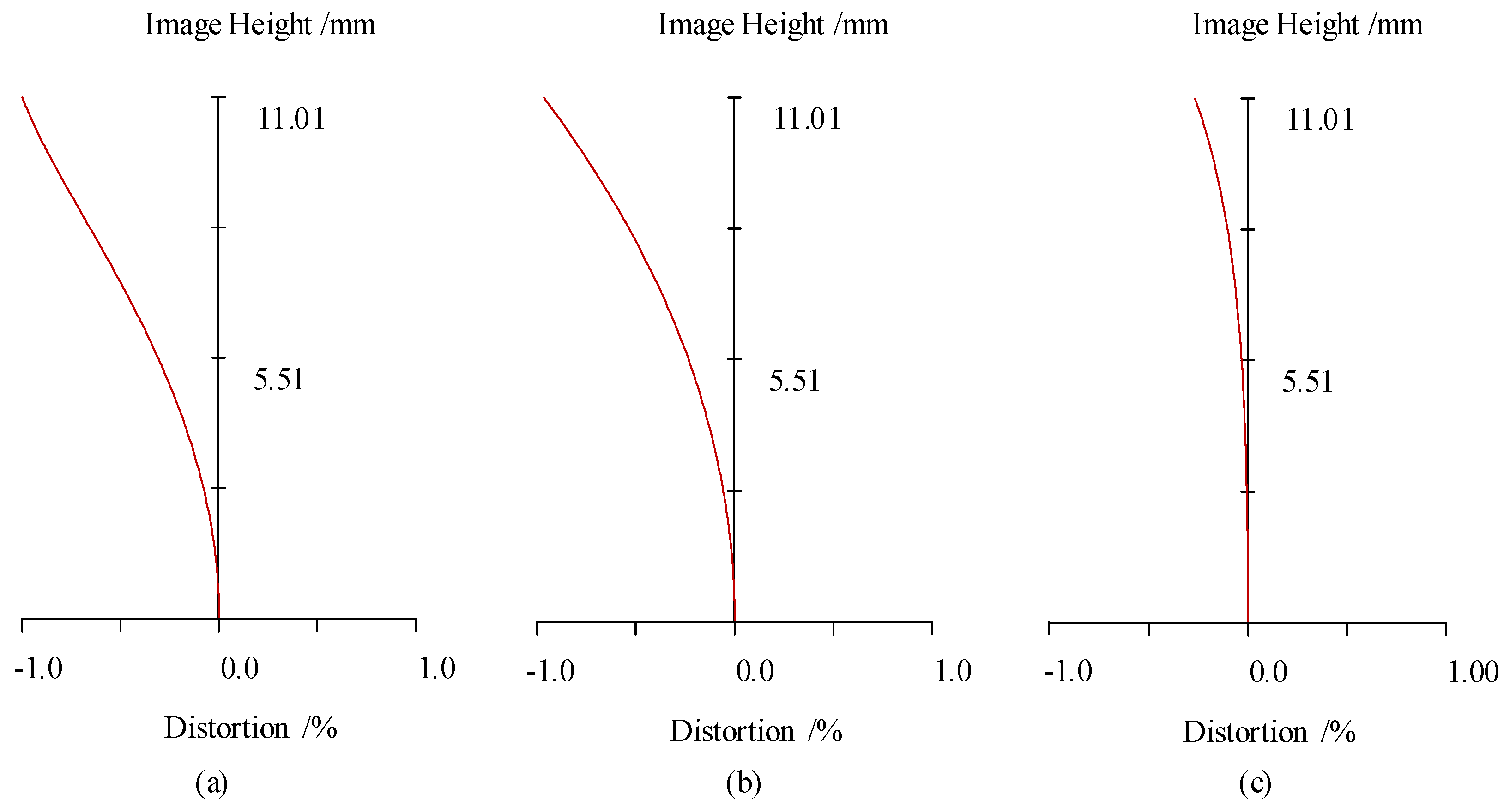
4.2. MTF and Relative Distortion

The image quality analysis of the 4× zoom lens included the MTF, and the relative distortion is shown in Figure 6. It is clear that best contrast at the field center of the telephoto zoom position was achieved at the cost of minor contrast performance in the edge of the image circle; the MTF value was greater than 0.4 at the cut-off frequency of 50 lp/mm. Figure 7 demonstrates the maximum relative distortion of −1.0% at EFL = 100 mm, −0.97% at EFL = 250 mm, and −0.27% at EFL = 400 mm, as EFL means effective focal length. Both of the above results confirmed that the optical system has good image quality. Also, the performance can be improved using more lenses or glass materials.

4.3. Tolerance Analysis

Fabrication errors, mounting errors, and material property-related errors were considered using Code V optical design software [20]. Opto-mechanically, the lenses of this zoom system are mounted in each group, and groups are integrated into the lens barrel to form the zoom system. Thus, in-group and among-group tolerance were used in the analysis and the relay (lens four and lens five) and the image location were selected as the alignment compensators. Eight fields were used to sample the FOV. Tolerances with an MTF reduction of approximately 0.1 at 50 lp/mm as given in Table 4 are practically applicable for manufacturing and yielding good quality.

5. Conclusions

In this paper, we proposed a paraxial design model to deal with the pupil walking issue in a zoom lens with an external pupil. The varifocal- and pupil-stable differential equation were presented, solving and using the equations with two-moving-parts zoom lens worked as guidance in the design process. Moreover, we designed a 4× zoom optical system that comprises four groups with two moving parts and achieves a continuous zoom range of 100 mm~400 mm and pupil walking of −3.9 mm to +4.3 mm. The system is being built and expected to be used in various cascaded or modular optics or other fields. Its performance will be demonstrated in the near future.

Author Contributions

Conceptualization, R.Q.; methodology, R.Q. and J.D.; software, R.Q. and K.L.; writing—original draft preparation, R.Q.; writing—review and editing, J.D. and J.Y.; supervision, J.C. All authors have read and agreed to the published version of the manuscript.

Funding

This research received no external funding.

Institutional Review Board Statement

Not applicable.

Informed Consent Statement

Not applicable.

Data Availability Statement

Data are available from the authors on request.

Conflicts of Interest

The authors declare no conflict of interest.

References

  1. Vizgaitis, J.N. Optical concepts for dual band infrared continuous zoom lenses. In Proceedings of the International Optical Design Conference 2010, Jackson Hole, WY, USA, 9 September 2010. [Google Scholar]
  2. Akram, M.N.; Asghar, M.H. Step-zoom dual-field-of-view infrared telescope. Appl. Opt. 2003, 42, 2312–2316. [Google Scholar] [CrossRef]
  3. Khatsevich, T.N.; Volkova, K.D. Stabilization of the exit pupil in an optical zoom sight with variable magnification. J. Opt. Technol. 2017, 84, 605–612. [Google Scholar] [CrossRef]
  4. Song, W.; Zhao, Y.; Berman, R.; Bodell, S.Y.; Fennig, E.; Ni, Y.; Papa, J.C.; Yang, T.; Yee, A.J.; Moore, D.T.; et al. Optimal power distribution for minimizing pupil walk in a 7.5x afocal zoom lens. In Proceedings of the International Optical Design Conference 2017, Denver, CO, USA, 27 November 2017. [Google Scholar]
  5. Wooters, G.; Silvertooth, E.W. Optically compensated zoom lens. J. Opt. Soc. Am. 1965, 55, 347–351. [Google Scholar] [CrossRef]
  6. Hopkins, H.H. 2-Conjugate Zoom Systems. In Optical Instruments and Techniques; Home-Dickson, J., Ed.; Oriel Press: London, UK, 1970; pp. 444–452. [Google Scholar]
  7. Hopkins, H.H. Zoom Lens System for Maintaining Two Pairs of Conjugate Planes Fixed. U.S. Patent 3619035, 9 November 1971. [Google Scholar]
  8. Bystricky, K.M.; Yoder, P.R. An improved zoom lens with external entrance pupil. In Proceedings of the Annual Technical Symposium, San Diego, CA, USA, 1 March 1974. [Google Scholar]
  9. Yeh, M.; Shiue, S.; Lu, M. First-order analysis of a two-conjugate zoom system. Opt. Eng. 1996, 35, 3348–3360. [Google Scholar] [CrossRef]
  10. Kryszczyński, T. Method to solve any paraxial pupil problems. In Proceedings of the Optical Science, Engineering and Instrumentation, San Diego, CA, USA, 25 September 1997. [Google Scholar]
  11. Mikš, A.; Novák, J. Three-component double conjugate zoom lens system from tunable focus lenses. Appl. Opt. 2013, 52, 862–865. [Google Scholar] [CrossRef] [PubMed]
  12. Miks, A.; Novak, J. Paraxial imaging properties of double conjugate zoom lens system composed of three tunable-focus lenses. Opt. Lasers Eng. 2014, 53, 86–89. [Google Scholar] [CrossRef]
  13. Novák, J.; Novák, P.; Mikš, A. Analysis of double conjugate zoom lens using tunable-focus lenses. In Proceedings of the Current Developments in Lens Design and Optical Engineering, San Diego, CA, USA, 25 September 2014. [Google Scholar]
  14. Mikš, A.; Novák, J. Method of first-order analysis of a three-element two-conjugate zoom lens. Appl. Opt. 2017, 56, 5301–5306. [Google Scholar] [CrossRef] [PubMed]
  15. Sarabia, C.M.G.; Castaneda, J.O. Two-conjugate zoom system: The zero-throw advantage. Appl. Opt. 2020, 59, 7099–7102. [Google Scholar] [CrossRef] [PubMed]
  16. Pal, S.; Hazra, L. Stabilization of pupils in a zoom lens with two independent movements. Appl. Opt. 2013, 52, 5611–5618. [Google Scholar] [CrossRef] [PubMed]
  17. Yu, X.; Wang, H.; Yao, Y.; Tan, S.; Xu, Y.; Ding, Y. Automatic design of a mid-wavelength infrared dual-conjugate zoom system based on particle swarm optimization. Opt. Express. 2021, 29, 14868–14882. [Google Scholar] [CrossRef] [PubMed]
  18. Kingslake, R.; Johnson, R.B. Lens Design Fundamentals; Academic Press: Cambridge, MA, USA, 2009. [Google Scholar]
  19. ChunKan, T. Design of zoom system by the varifocal differential equation. I. Appl. Opt. 1992, 31, 2265–2273. [Google Scholar] [CrossRef] [PubMed]
  20. Synopsys. CODE V Optimization Reference Manual; Synopsys: Pasadena, CA, USA, 2017. [Google Scholar]
Figure 1. Schematics of the general zoom lens design model.
Photonics 09 00191 g001
Figure 2. Schematics of the zoom lens design model.
Photonics 09 00191 g002
Figure 3. Solution of VDE and PSDE with NFOV inputs as the initial parameters.
Photonics 09 00191 g003
Figure 4. Design result of the 4× zoom lens with a stable entrance pupil and internal stop at focal length: (a) 100 mm; (b) 250 mm; and (c) 400 mm.
Photonics 09 00191 g004
Figure 5. Cam curve and pupil walking of the proposed design. (a) Cam curve of the 4× zoom optical system, and (b) Pupil walking of the 4× zoom lens.
Photonics 09 00191 g005
Figure 6. Corresponding MTF performance of the zoom lens at focal length: (a) 100 mm; (b) 250 mm; and (c) 400 mm.
Photonics 09 00191 g006
Figure 7. Distortion performance of the zoom optical system at focal length: (a) 100 mm; (b) 250 mm; and (c) 400 mm.
Photonics 09 00191 g007
Table 1. Specifications for the 4× zoom objective.
PropertySpecifications
Wavelength500 nm~750 nm
Effective focal length100 mm~400 mm
Diagonal image size22 mm
f-number10
Maximum relative distortion≤1%
Modulation transfer function≥0.4 at 50 lp/mm (at whole FOV)
Pixel size10 μm
Entrance pupil distance35 mm
Pupil walking≤10 mm
Back focal length≥20 mm
Total length≤370 mm
Table 2. Initial lens structure of the 4× zoom objective (unit: mm).
f   t E P   f 1   t 1   f 2   m 2   t 2   f 3   m 3   t 3   f 4   m 4   t E X P  
100357866.18−19.52.544.2737.060.5966.0521.6−0.855
400357865−19.5357.537.0621021.6−0.855
Table 3. Lens data results for the 4× zoom lens system.
SurfaceRadius
(mm)
Thickness
(mm)
Material
ObjectInfinityInfinity
1Infinity35.00
243.8410.00HFK95N
3−131.837.18
476.374.67HLAF1
5405.953.93
6−80.897.16HZF52
755.1876.34
8247.345.87HZF52
9−85.980.30
1038.975.75HZLAF92
1184.124.57~11.78
12−771.414.40HZLAF92
13−53.232.50HFK95N
1419.925.11
15−25.722.50HLAF1
1628.170.52
1729.174.07HZF52
1871.9871.60~11.09
19102.334.74HLAF1
20−58.660.30
2149.226.73HBAF3
22−25.792.50HZF1
2350.503~56.30
2444.493.59HZLAF92
25101.520.30
2630.773.88HZF88
2781.508.08
28−42.9813.85HFK95N
29−20.783.00
StopInfinity3.00
31−10.132.50HZF88
3221.840.53
3330.323.70HBAF3
34−20.730.30
35269.464.19HBAF3
36−13.4554.35
ImageInfinity0
Table 4. Tolerances for the zoom lens system proposed.
TypePropertyTolerances
Manufacture tolerancesRadius±3 fringe
Irregularity±0.2 fringe
Index variation±0.0003
Abbe number±0.5%
Center thickness±0.01 mm
Tilt±1′
Decenter±0.01 mm
Mounting tolerancesDecenter±0.01 mm
Tilt±1′
Integrating tolerancesDecenter±0.02 mm
Tilt±1′
Publisher’s Note: MDPI stays neutral with regard to jurisdictional claims in published maps and institutional affiliations.

