Abstract
The bit error ratio (BER) performance of a non-orthogonal multiple access (NOMA) visible light communication (VLC) system is poor due to the unequal distances between adjacent points in the superposition constellation (SC). In this paper, we propose a novel scheme to improve the BER performance by adjusting parameters to change the shape of SC at the transmitter and by adjusting the parameters of successive interference cancellation (SIC) decoding at the receiver simultaneously, which is called a SC and SIC adjustment (SC-SIC-A) scheme. For multi-user NOMA VLC system, we derive the closed-form BER expression for each user, where the modulation format is four-quadrature amplitude modulation. According to the derived BER expressions, we formulate an optimization problem that minimizes the average BER for all users by adjusting the obtained parameters of SC and SIC decoding via differential evolution algorithm. The improvement of capacity performance is investigated consequently. In order to verify the feasibility and effectiveness of the proposed SC-SIC-A scheme, we carried out theoretical analysis, Monte Carlo simulation and experiments of two-user and three-user NOMA VLC systems. Results show that the SC-SIC-A scheme outperforms the existing schemes in NOMA VLC system, where the signal-to-noise ratio (SNR) reductions to achieve BER of are 1.3 dB and 0.8 dB for both users in the two-user NOMA VLC system, respectively, and the SNR reductions to achieve BER of are 5.7 dB, 4.3 dB and 4.6 dB for all users in the three-user NOMA VLC system, respectively.
1. Introduction
As fifth generation (5G) mobile communication and the Internet of things emerge, a large number of data-intensive applications have been born, resulting in the exponential growth of data traffic [1,2]. The conventional radio frequency (RF) spectrum cannot meet the requirement of high data transmission due to its limited spectrum resource [3]. As a good solution for satisfying the spectrum requirement, visible light communication (VLC) has attracted considerable attention for the wireless network due to its abundant unlicensed spectrum, immunity to electromagnetic interference, low energy consumption and effective frequency and spatial reuse [4,5,6]. VLC is carried out by using the illumination infrastructure with light-emitting diode (LED), where illumination and communication are implemented simultaneously. With the popularity of LED as a light source in indoor and outdoor environments, VLC has become a green and energy-saving communication method [7]. However, the modulation bandwidth of LED is only tens of megahertz (MHz), which limits the capacity of a VLC system [8]. The capacity of VLC system can be increased by adopting advanced modulation formats, which is carried out under orthogonal frequency division multiplexing (OFDM) [9,10]. It has been demonstrated that the spectral efficiency, fairness and capacity performance of multi-user OFDM VLC systems could be further improved by employing non-orthogonal multiple access (NOMA). Meanwhile, NOMA could significantly improve the quality and reliability of reception in OFDM VLC systems due to different power allocation among all users [11,12].
NOMA is an attractive and efficient access method for wireless network, which allows multiple terminals to use the same resources, such as time and frequency [13]. NOMA has the advantages of high spectral efficiency, high flexibility, low transmission latency and improved fairness [14,15,16]. Superposition coding and successive interference cancellation (SIC) decoding are two key techniques in the NOMA scheme. The performance analysis and optimization of NOMA VLC system have been widely studied. The theoretical bit error analysis of a downlink NOMA VLC system based on a high-order modulation scheme is investigated in [17]. In [18], the bit error ratio (BER) performance of a two-user NOMA VLC system using different modulation formats was investigated. In order to improve the system’s performance, the method of adjusting superposition constellation (SC) has been proposed in the literature. The poor SC due to different arrival times is compensated by phase predistortion method [19]. Moreover, SC can be adjusted based on convex optimization [20]. The above works are the research of the two-user NOMA VLC system. To improve system capacity and spectral efficiency, NOMA technology should be used to serve more users in one resource block. However, with the increase in the number of users, the interference among users becomes severe, resulting in the deterioration of system performance. Thus, the performance of NOMA VLC system supporting three or more users has been investigated in [21,22]. The BER performance under noisy channel state information is researched in [21], while in [22], the capacity region of a practical uplink NOMA for multiple users is investigated. Nevertheless, for multiuser NOMA VLC system using 4-quadrature amplitude modulation (QAM), the closed-form BER expressions for all users as well as the improvement of BER and capacity performance have not been studied.
In this paper, we propose a joint transceiver optimization scheme to improve the BER and capacity performance of a multi-user NOMA VLC system using 4-QAM-OFDM. Since the distances between adjacent points in the SC are quite different, the BER performance of multi-user NOMA VLC system is poor. Therefore, adjustment parameters are introduced to change the shape of SC at the transmitter [20]. This scheme is called the superposition constellation adjustment (SC-A) scheme. We notice that, under the SC-A scheme, the power allocation coefficients are no longer optimal for SIC decoding at the receiver. Thus, the joint transceiver optimization scheme was proposed, which is called the SC and SIC adjustment (SC-SIC-A) scheme. In this scheme, we adjust the parameters of the SC at the transmitter and that of the SIC decoding at the receiver to improve the performance of the downlink multi-user NOMA VLC system without increasing the overall transmitted power of signal. More specifically, we derive the closed-form BER expression of each user in detail under the SC-SIC-A scheme. Meanwhile, we find the rule for the number of terms in each user’s BER expression, which is named as NOMA triangle regarding the terms of Q-function. According to the derived BER expressions, an optimization problem is formulated to minimize the average BER for all users by adjusting the parameters of SC at the transmitter and that of SIC decoding at the receiver. The optimization problem is solved by the differential evolution (DE) algorithm to obtain the optimal adjustment parameters. In addition to BER performance, the expression of channel capacity for each user under the proposed SC-SIC-A scheme is also derived. When the optimal adjustment parameters are applied to the SC-SIC-A scheme, capacity performance is also improved. In order to demonstrate the effectiveness and feasibility of the proposed SC-SIC-A scheme, we carry out theoretical analysis, Monte-Carlo (MC) simulation, and experiment, where the results match very well. The results show that compared with the SC-A scheme, the SC-SIC-A scheme provides 1.3-dB and 0.8-dB signal-to-noise ratio (SNR) reductions to achieve BER of for two-user NOMA VLC system, respectively, and provides 5.7-dB, 4.3-dB and 4.6-dB SNR reductions to achieve the BER of for three-user NOMA VLC system, respectively.
This paper extends its conference version [23] from the following aspects. Firstly, we derive the closed-form BER expression for each user in the multi-user NOMA VLC system under the SC-SIC-A scheme. Secondly, the capacity expression for each user under the proposed scheme is derived. Thirdly, the BER and capacity performance of NOMA VLC system are analyzed when the number of users is two and three. Finally, the indoor NOMA VLC experiment is carried out in this paper to demonstrate the feasibility of the proposed scheme.
The remainder of the paper is organized as follows. Section 2 describes the scheme of SC-SIC-A for multi-user NOMA. The performance analysis and optimization by using joint SC and SIC decoding adjustment are presented in Section 3. Section 4 shows the results and discussions, and the conclusion is finally provided in Section 5.
2. System Model
The schematic of multi-user NOMA VLC system using joint transceiver optimization is shown in Figure 1. We assume that there are K users in the NOMA VLC system. LED transmits signals to the K users simultaneously. The data of each user contain bits, which are mapped to the constellation point by using 4-QAM. K signals are superposed, where the power allocation coefficients for K users are denoted by . Note that . Under the K-user NOMA scheme, users with lower channel gain will be allocated higher power to ensure fairness. In this paper, we assume that channel gains are identical, i.e., , and the power allocation coefficients follow . Thus, the original superposed NOMA signal can be written as follows.
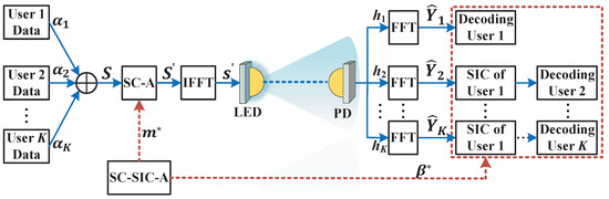
Figure 1.
The schematic of the downlink multi-user NOMA VLC system using joint transceiver optimization.
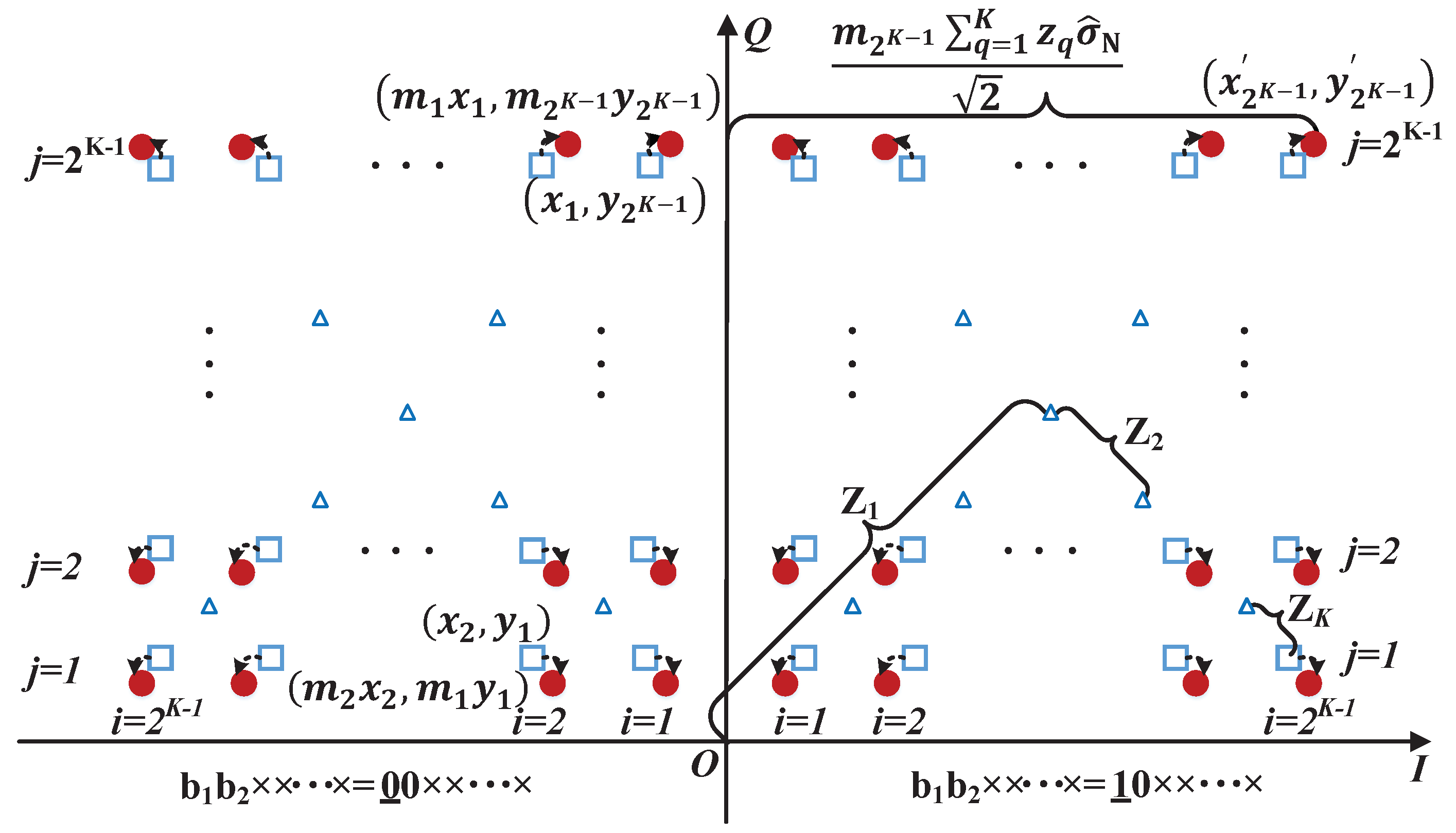
Regarding the constellation of the superposed signal S, the distances between the adjacent points are quite different from each other. We take the SC-A scheme to adjust SC and, therefore, to improve BER performance. The illustration of the SC-A process is shown in Figure 2, where the first and second quadrants of SC are taken into consideration. Since the SC is symmetric, we need to use scale parameters to adjust the SC for K-user NOMA VLC system. The SC scale parameter vector is identical for horizontal and vertical directions. Under the SC-A scheme, the original point is adjusted to . Accordingly, the original superposed signal S is converted to . The total transmitted power of the signal is converted from P to .
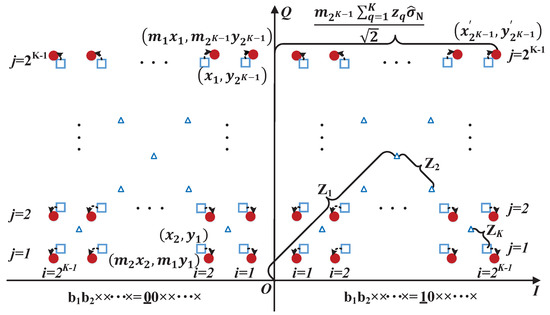
Figure 2.
The demonstration of SC-A in the first and second quadrants. Triangle: the intermediate points of superposition signals in constellation before SC-A; square: the points of the SC before SC-A; circle: the points of the SC after SC-A.
After taking inverse fast Fourier transform (IFFT), the frequency-domain signal is converted to the time-domain OFDM signal , which drives the LED under direct current (DC) bias [24]. Thus, the modulated light x at the output of LED is as follows:
where is the current-to-light conversion efficiency of LED, and is the DC bias.
The LED output light x propagates through an indoor channel. If only line-of-sight (LoS) propagation is considered, the channel gain between the LED and the user k is given by the following [25].
In Equation (5), A is the physical area of photo-detector (PD), and is the order of Lambertian emission, where is the semiangle at half power. is the distance between the LED and user k, is the emission angle, is the angle of incidence, and is the gain of an optical filter. is the gain of an optical concentrator, where is the concentrator field of view (FOV) semiangle and denotes the refractive index.
The modulated light is collected by PD, which converts it into an electrical signal. After removing the DC component, the signal for user k is as follows:
where R is the responsivity of PD, and is the additive white Gaussian noise (AWGN) with a mean of zero and the variance of . can be normalized as follows:
where is the normalized noise with the mean of zero and the variance of .
The fast Fourier transform (FFT) module converts the normalized signal to the frequency-domain signal , where is the normalized noise in frequency domain. , where and are the real part and imaginary part of , respectively. After that, the SIC algorithm is used to decode each user’s data from . Since the SC-A scheme is used at the transmitter, the original power allocation coefficients are no longer optimal for SIC decoding. We should find the optimal parameters to replace in the procedure of SIC decoding. The entire process that contains the parameter adjustment for SC at the transmitter and for SIC at the receiver is called an SC-SIC-A scheme.
3. Performance Analysis and Optimization under SC-SIC-A Scheme
In this section, we investigate the BER and capacity performance of the multi-user NOMA VLC system under SC-SIC-A scheme. We derive the BER expressions of all K users, where the rule for the number of terms in each user’s BER expression is found. We formulate an optimization problem to minimize the average BER by jointly adjusting the parameters of SC and SIC decoding. Based on the same optimized parameters, the capacity performance of multi-user NOMA VLC systems under SC-SIC-A scheme is also studied.
3.1. Derivation of BER
We derive the BER expressions of all the K users under the SC-SIC-A scheme. The SNR of user k is defined as . As depicted in Figure 2, each point of SC represents bits, which can be denoted by , , …, . , and are the information bits of 4-QAM signals for all the K users, respectively. The original scales of the K users’ 4-QAM signals are denoted by , , respectively. We have , where , . Then, the BER expressions of all the K users can be derived as follows.
3.1.1. BER Expression of User 1
Firstly, we derive the BER expression of bits for user 1. Due to the symmetry of the adjusted SC, the BER of for user 1 in the first quadrant is the same as that in the rest three quadrants. Since the detection of for user 1 in the vertical direction follows the same principle as that of in the horizontal direction, we have . As shown in Figure 2, each quadrant of the SC can be divided into columns. The BER for the in-phase components of the points in each column are the same, while the BERs for the in-phase components in various columns are different from each other. Thus, the BER expression is as follows:
where the set represents the indices of columns in any quadrant as shown in Figure 2, stands for the operation of expectation and is the error probability of for user 1 at the adjusted SC point . Therefore, the BER expression of user 1 in Equation (8) is derived as follows:
where the detailed derivation process of is shown in Appendix A.1.
3.1.2. BER Expression of User 2
Secondly, we derive the BER expression of bits for user 2. The BER performance of user 2 is affected by the previous bits detection of user 1 under the SIC scheme. Erroneous detection for user 2’s bits can be found by both the conditions that user 1’s bits are detected correctly and incorrectly. Thus, based on the derivation principle of user 1’s BER expression, we can obtain the BER expression of user 2 as follows:
where is the error probability of for user 2 at the adjusted SC point , represents user 1 and stands for the detection result of user 1’s bit. The index represents the conditions that ’s bits are detected correctly and wrongly, respectively. Thus, the BER expression of user 2 in Equation (10) can be written as follows:
where the detailed derivation processes of and are shown in Appendix A.2.
3.1.3. BER Expression of User k
Finally, we derive the BER expression of bits for user k. The BER of user k is affected by the previous bits detection of k − 1 users. Thus, there are conditions for the detection of user k. Thus, based on the derivation principles of for user 1 and for user 2 at the adjusted SC point , the BER of user is as follows:
where , . stands for the previous detection results of users’ bits, which represent the conditions that user ℓ’s bit is detected correctly or incorrectly . Let be the power allocation coefficient vector and be the SIC decoding parameter vector. When , Equations (9) and (12) reduce to the BER expressions for K-user NOMA VLC system under the SC-A scheme.When and SC scale parameter vector , Equations (9) and (12) reduce to the BER expressions for the conventional NOMA VLC system without any adjustments.
Note that as the number of users increases, i.e., , the BER expression of user 4 is affected by SIC decoding parameters at the receiver. The reason for how SIC decoding parameters at the receiver affect the BER expression is described in Appendix A.3, where we find that the bit error does not exist under certain SIC decoding parameters. Therefore, Equation (12) holds under the following restrictions
When the restrictions in Equation (13) are not satisfied, the overlapping part of the decision regions for all users is affected by , and , which is consistent with Case II in Appendix A.3. Thus, some parts in Equation (12) become zero under certain , and , i.e., when , the in Equation (12) becomes zero.
3.2. NOMA Triangle Regarding the Terms of Q-Function
When the modulation format is 4-QAM, the BER expressions of user k under K-user NOMA VLC system are shown in Equations (9) and (12), where Equations (9) and (12) apply to user 1 and user , respectively. As shown in Equations (9) and (12), the BER expression for a particular user under the multi-user NOMA VLC system is the summation of the Q-function. Based on the derivation principles of BER expressions in the Section 3.1, the BER of user k is affected by the previous detection results of k − 1 users. Thus, there are conditions for the detection of user k. As the conditions number of detection increases, the number of terms for BER expressions in terms of Q-function also grows.
In order to investigate the BER expression for each user, we list the number of terms for each user’s BER expression in Table 1, where stands for the number of users in NOMA VLC system, represents the number of terms for a particular user’s BER expression and represents a particular user under K-user NOMA scheme. The value of for each user’s BER expression does not take and into account, since and . Note that, in the vertical direction of Table 1, when the number of superimposed users increases by one under NOMA scheme, the number of terms for the BER expressions doubles under the same . We can see that, under the K-user NOMA VLC system, the number of terms of BER expressions for K users includes , respectively. According to the rule shown in the Table 1, we can obtain the number of terms for each user’s BER expression under K-user NOMA scheme. Since the number of terms for BER expressions for K users is distributed as a triangle in Table 1, we name this rule as NOMA triangle regarding the terms of Q-function.

Table 1.
NOMA triangle regarding the terms of Q-function for K-user NOMA VLC system using 4-QAM.
3.3. Optimization of BER Performance
We would like to find the minimum average BER under the SC-SIC-A scheme. The BER expressions are a function of SC scale parameters and the SIC decoding parameters . Thus, we establish an optimization problem to improve BER performance of a multi-user NOMA VLC system by joint optimization of the vector of SC scale parameters and the vector of SIC decoding parameters . The minimization of average BER among K users is used as the objective function, which can be formulated as follows:
where (C1) and (C2) are the constraints of problem (14), and (C1) guarantees that the total transmitted power of signal after adjustment is no larger than that before the adjustment and (C2) is used to maintain the same decoding order as that of the conventional NOMA VLC system without any adjustments. Due to the robustness of DE algorithm in optimization problems, the problem (14) is solved by DE algorithm [26]. By using the DE algorithm, the optimal SC scale parameters and the SIC decoding parameters are obtained. When only (C1) is considered, the optimization problem (14) for the proposed SC-SIC-A scheme is simplified to that for the SC-A scheme.
3.4. Derivation of Capacity
We derive the capacity expression of each user in the K-user NOMA VLC system under the SC-SIC-A scheme. The channel capacity of user 1 can be written as , where I represents the mutual information, stands for the transmitter data of user 1 and is the superposition signal at the receiver of user 1 under the SC-SIC-A scheme, which is the function of SC scale parameters . Then, can be derived as follows:
where the following is the case.
Based on the same principle, the capacity of user k can be derived as follows:
where is the superposition signal at the receiver of user k, represents the transmitter data of user 1 and . Then, can be written as follows:
where the following is the case.
4. Results and Discussion
In this section, without loss of generality, we investigate the BER and capacity performance for multi-user NOMA VLC system by letting and . We present the results of theoretical analyses, MC simulations and experiments compared with other benchmark schemes to show the effectiveness and feasibility of the proposed SC-SIC-A scheme in Figure 1. The parameters of DE algorithm, MC simulation and experiment in NOMA VLC system are listed in Table 2, Table 3 and Table 4.
Table 2.
DE algorithm parameters.
Table 3.
Simulation parameters [25,27,28].
Table 4.
Experiment parameters.
4.1. Benchmark Schemes
The BER and capacity performance of the proposed SC-SIC-A scheme in Figure 1 is compared with two benchmark schemes, which are called the no adjustment scheme and the SC-A scheme. The no adjustment scheme superimposes user signals by using NOMA without adjusting the parameters of SC or SIC decoding, while the SC-A scheme adjusts the parameters of SC at the transmitter. Note that the SC-A scheme for two-user NOMA VLC system was proposed in [20]. In this work, for comparison, the SC-A scheme has been applied to two-user and three-user NOMA VLC systems, respectively.
4.2. Theoretical Analysis and MC Simulation
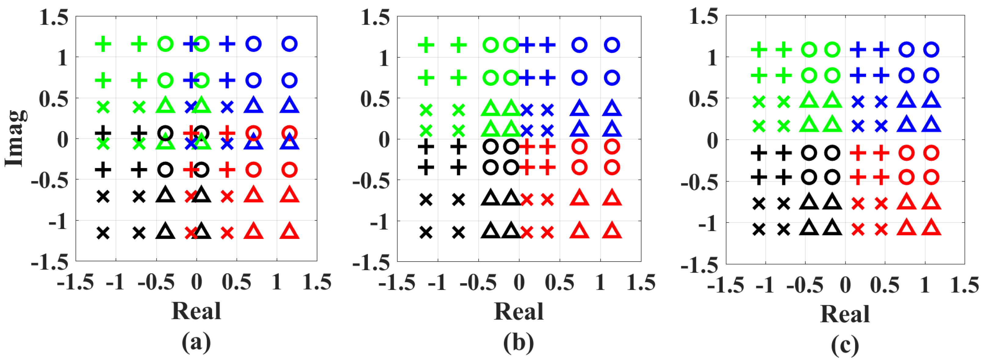
We analyze the BER performance of the multi-user NOMA VLC system by letting . The SCs under the three schemes are depicted in Figure 3, where the adjusted parameters are obtained according to the optimization problem (P), when is 21 dB. We can see that, under the SC-SIC-A scheme, all four points with the same color are confined in one quadrant and the distances between adjacent points in constellation are almost identical compared with that under the SC-A scheme and under the no adjustment scheme. Thus, an improved BER performance for all users can be expected under the SC-SIC-A scheme.
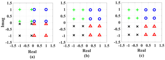
Figure 3.
The SCs of (a) the no adjustment scheme, (b) the SC-A scheme and (c) the SC-SIC-A scheme. The parameters of (b,c) are obtained, when and . Colours and markers are used to distinguish the data of user 1.
The BER performance is shown in Figure 4, where the results of theoretical analysis and MC simulation match very well. Note that under the no adjustment scheme, user 1 and user 2 can achieve the BER of when is 23.9 dB, for which its corresponding BER curves basically coincide. Under the SC-A scheme, to achieve BER of decreases from 23.9 dB to 14.8 dB for user 1, and the value of to achieve BER of decreases from 23.9 dB to 15.7 dB for user 2 at the same time. Under the proposed SC-SIC-A scheme in Figure 1, the obtained vectors of optimal adjustment parameters are and , when is 21 dB. With and , the equality in (C1) holds, and is smaller than and very close to 1. Moreover, we can see that the optimal power allocation coefficients for SIC decoding are different from the original power allocation coefficients . The values of to achieve the BER of are 13.5 dB and 14.9 dB for the two users, respectively. Compared with the no adjustment scheme, the corresponding reductions in to achieve the BER of are 9.1 dB and 8.2 dB for the two users, respectively. Meanwhile, the corresponding reductions in to achieve the same level of BER are 1.3 dB and 0.8 dB, respectively, compared with the SC-A scheme.
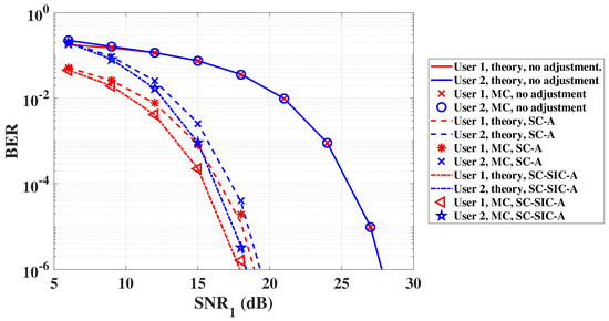
Figure 4.
The BER performance for each user of multi-user NOMA VLC system, when .
Then, we analyze the performance of the multi-user NOMA VLC system by letting . The SCs under three schemes when is 21 dB are shown in Figure 5. We can see that, under the no adjustment scheme, some of the points with one colour enter the adjacent quadrants with another colour, which deteriorates BER performance and leads to error floors of all users. Meanwhile, under the proposed SC-SIC-A scheme, all 16 points with the same colour are confined in the corresponding quadrants and the distances between adjacent points in constellation are almost identical compared to that under the no adjustment scheme and SC-A scheme. Thus, a better BER performance can be achieved by jointly adjusting the parameters of SC at the transmitter and SIC decoding at the receiver.

Figure 5.
The SCs of (a) the no adjustment scheme, (b) the SC-A scheme and (c) the SC-SIC-A scheme. The parameters of (b,c) are obtained, when and . Colours are used to distinguish the data of user 1, and markers are used to distinguish the data of user 2 when user 1’s data are detected.
The BER performance of three-user NOMA VLC system is shown in Figure 6, where the results of theoretical analysis and MC simulation match very well. We can find that all three users cannot achieve the BER of , and the error floors for all users can be observed under the no adjustment scheme. Under the SC-A scheme, the error floors are eliminated, and the values of to achieve the BER of are 24.3 dB, 24.3 dB and 25.8 dB for the three users, respectively. Under the SC-SIC-A scheme in Figure 1, the obtained vector of optimal adjustment parameters are and , when is 21 dB. Moreover, note that the optimal adjustment parameters for SIC decoding are different from the original power allocation coefficients due to the SC adjustment at the transmitter. With joint transceiver optimization, the values of to achieve the BER of are 18.6 dB, 20.0 dB and 21.2 dB for the three users, respectively. The reductions in to achieve BER of are 5.7 dB, 4.3 dB and 4.6 dB for the three users, respectively, comparing to the BER performance under SC-A scheme. When is 21 dB, the SCs in the three schemes are shown in the Figure 3 and Figure 5, by letting and . It can be found that the adjusted SC is clearer. Therefore, BER performance is improved. The reductions to achieve BER of by using the SC-SIC-A scheme compared with SC-A scheme under various power allocation coefficients are shown in Table 5, from which we can observe that the SC-SIC-A scheme performs almost better than the SC-A scheme under various power allocation coefficients. We can conclude that whether it is the two-user or the three-user NOMA VLC system, BER performance is significantly improved under the SC-SIC-A scheme.
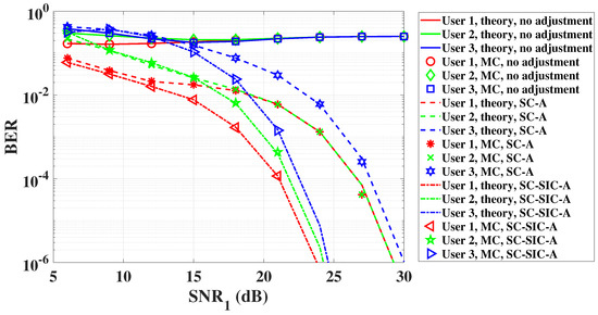
Figure 6.
The BER performance for each user of multi-user NOMA VLC system, when .
Table 5.
The reductions to achieve BER of by using the SC-SIC-A scheme compared with SC-A scheme under various power allocation coefficients.
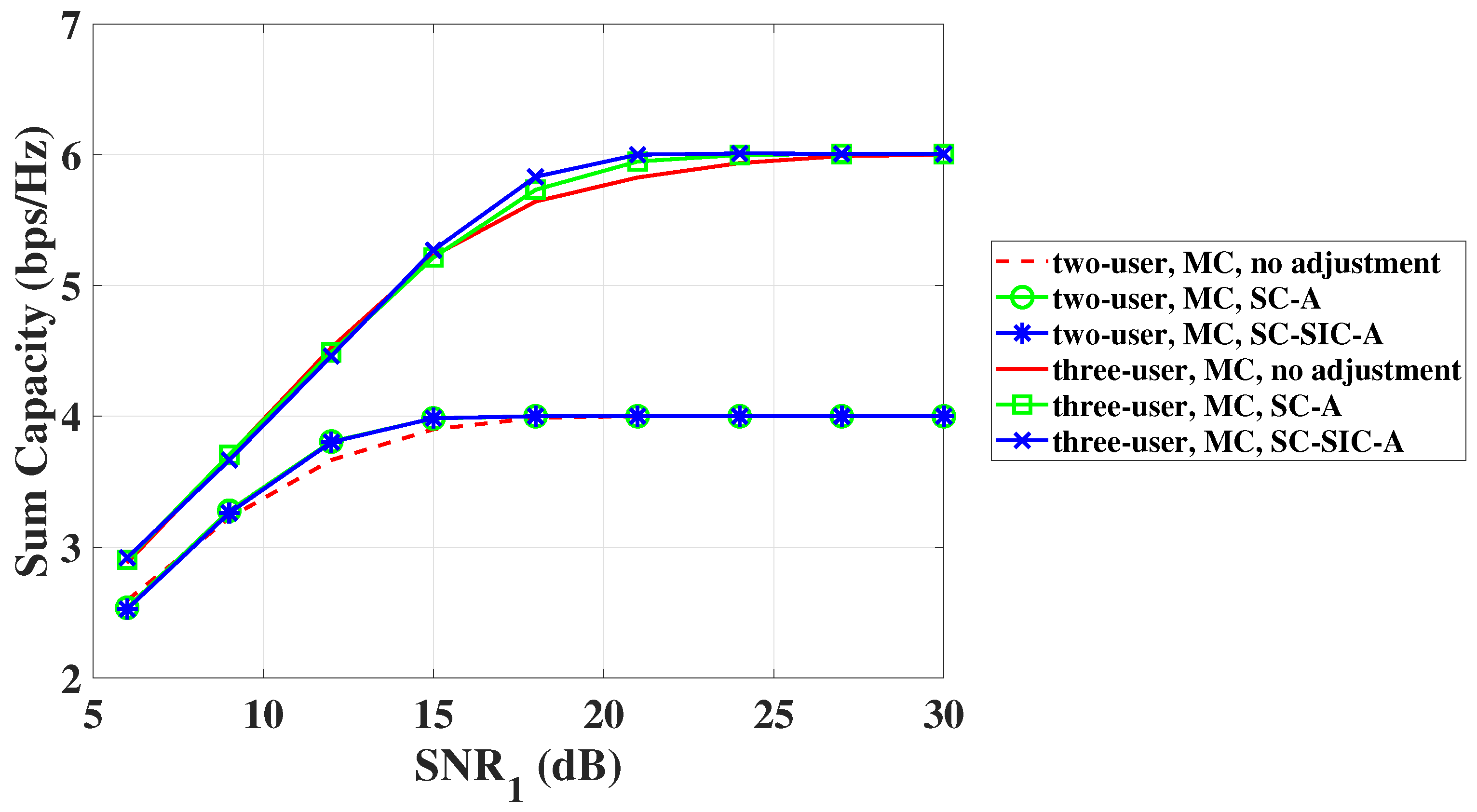
The sum capacity performance of the multi-user NOMA VLC system with and is shown in Figure 7. To begin with, we analyze the sum capacity performance of the two-user NOMA VLC system. We can observe that the sum capacity increases very slowly and achieves its maximum value when is 27.0 dB under the no adjustment scheme. Under the SC-A scheme, the value of making the sum capacity achieve 4 bps/Hz is 15.0 dB. The reduction in to achieve sum capacity of 4 bps/Hz is 12.0 dB. Under the SC-SIC-A scheme, the value of is 15.0 dB, when the sum capacity achieves 4 bps/Hz, which is the same as the SC-A scheme. Then, we analyze the sum capacity performance of NOMA VLC system, when . We can find that, when SC is not adjusted, sum capacity increases very slowly and reaches its maximum value until is 29.8 dB. Under the SC-A scheme, the value of making the sum capacity achieve 6 bps/Hz is 25.0 dB, which is smaller than that under the no adjustment scheme. However, the value of to achieve the maximum of sum capacity is 24.0 dB under the SC-SIC-A scheme. Meanwhile, when is more than 13.7 dB, the sum capacity curve acquired by the SC-SIC-A scheme performs better than others. Therefore, the sum capacity performance is improved.

Figure 7.
The sum capacity of multi-user NOMA VLC system, when and .
4.3. Experiment
In this part, we verify the improvement of BER performance of multi-user NOMA VLC systems by conducting an experiment. Due to the limitation of devices, the maximum SNR during signal detection is about 20 dB. Therefore, the verification of experiment is carried out in indoor environments under two-user and three-user NOMA VLC systems as examples.
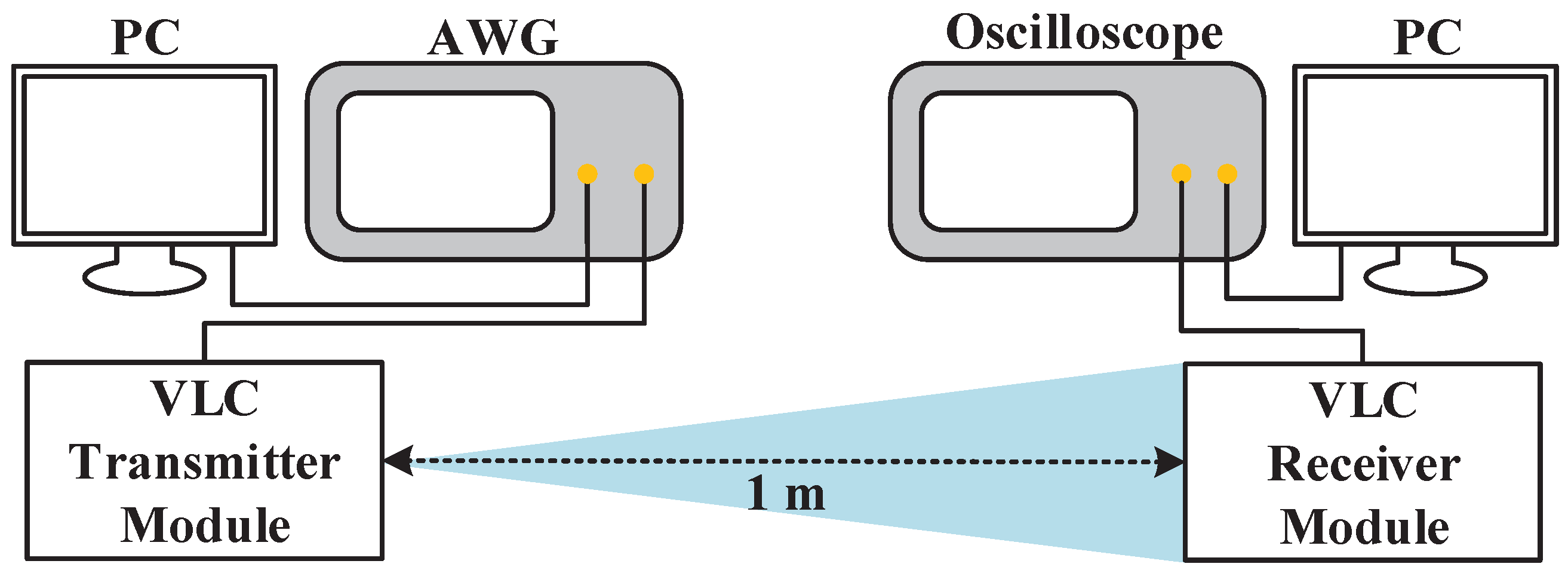
The experimental setup of the NOMA VLC system is shown in Figure 8. The two users’ 4-QAM data are generated offline using MATLAB in personal computer (PC). The two 4-QAM data with particular power allocation coefficient are superposed to generate a frequency-domain NOMA signal, which is converted to the time-domain OFDM signal, after passing through 64-point IFFT module. Note that Hermitian symmetry is used to the generate real-valued OFDM signal. Two thousand OFDM signals were uploaded to the arbitrary waveform generator (AWG) (RIGOL DG1062Z) with a sampling rate of 10 MSa/s. Subsequently, the signal generated by AWG drives the VLC transmitter module (HCCLS2021MOD01-TX), which converts the electrical signal into modulated light. After 1 m propagation, the modulated light reaches the VLC receiver module (HCCLS2021MOD01-RX), which converts it back to electrical signals. The converted electrical signal is captured by the oscilloscope (ROHDE&SCHWARZ RTE1022) and is downloaded to the PC for offline processing.
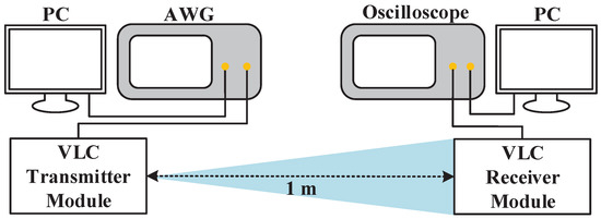
Figure 8.
Experimental setup of the NOMA VLC system.
The experimental parameters are shown in Table 4, where the vectors of power allocation coefficient of two-user and three-user NOMA VLC systems are and , respectively. In the experiment, the values of are changed under different powers of the transmitted signal. Therefore, we change the transmitted signal power by changing the voltage peak value of transmitted signal from 50 mV to 250 mV. BER performance is obtained under various .
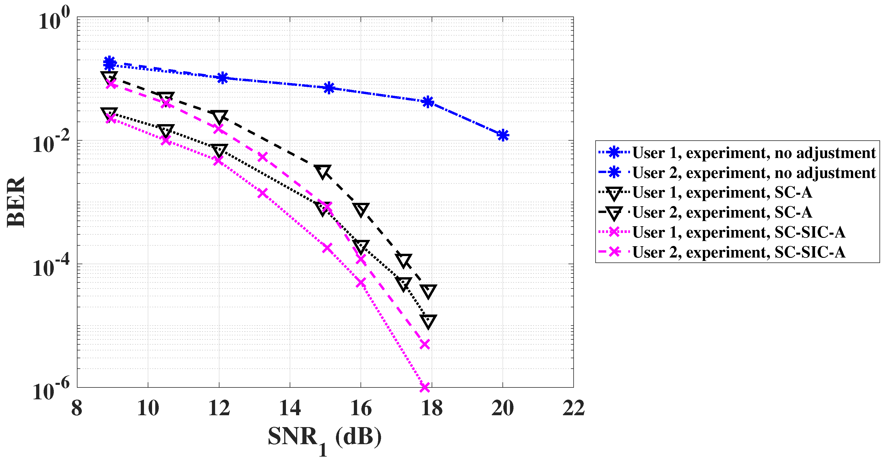
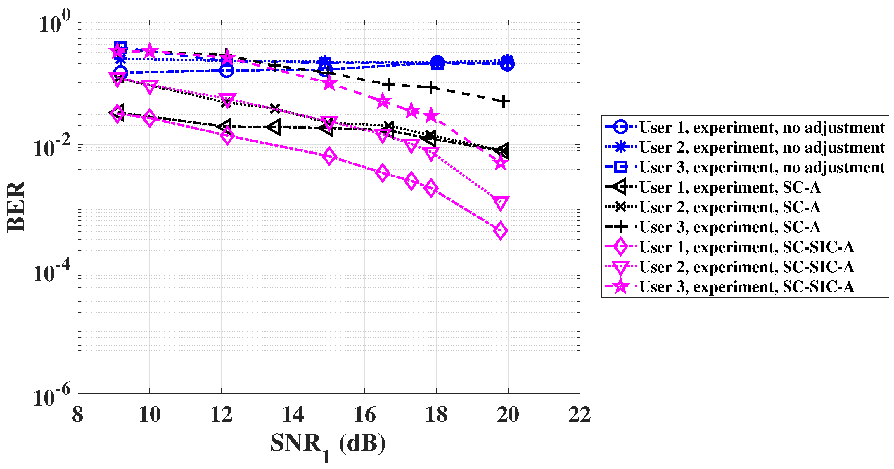
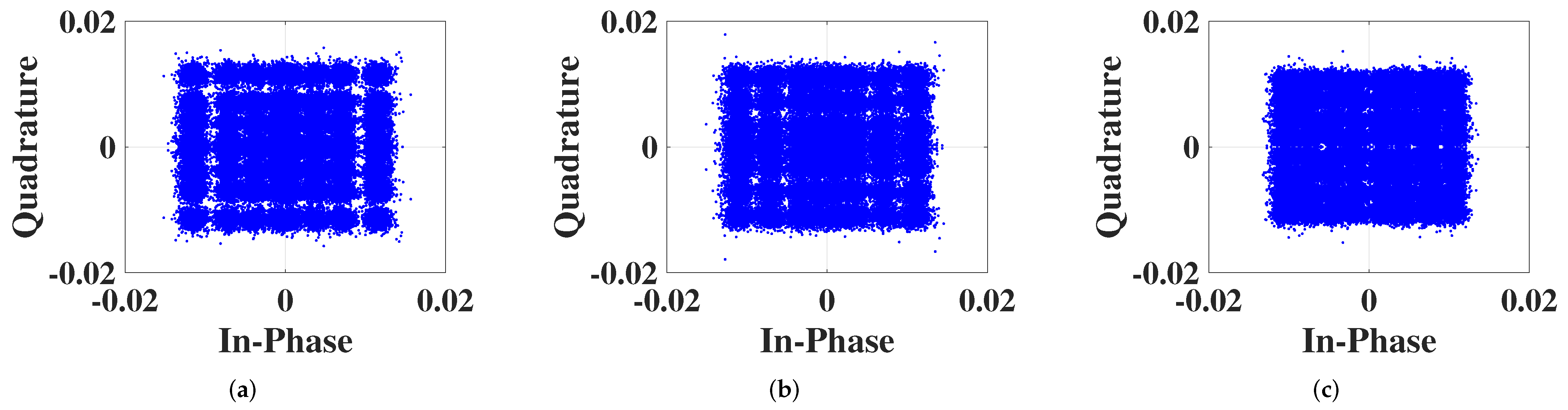
BER performance when is shown in Figure 9. Under the no adjustment scheme, user 1 and user 2 cannot achieve the BER of with in the range of 9 dB to 20 dB. Under the SC-A scheme, the values of to achieve the BER of are 14.7 dB and 15.8 dB for the two users, respectively. Under the SC-SIC-A scheme, the values of to achieve the BER of are 13.5 dB and 14.9 dB for the two users, respectively. Compared with the SC-A scheme, the corresponding reductions in to achieve the same level of BER are 1.2 dB and 0.9 dB, respectively. In addition, from the Figure 4 and Figure 9, we can see that the results of theoretical analysis and experiment match very well under different values of . BER performance when is shown in Figure 10. Under the no adjustment scheme, when the value of is between 9 dB and 20 dB, the error floors of all three users can be observed. Under the SC-A scheme, the BER of all the three users cannot reach in the experiment. Under the SC-SIC-A scheme, although user 3 cannot achieve the BER of , user 1 and user 2 can achieve the BER of when the values of are 18.7 dB and 20.0 dB, respectively. Note from Figure 6 and Figure 10 that the results of theoretical analysis and experiment also match well when . The SCs under the three schemes obtained by experiment at the receiver are shown in the Figure 11 and Figure 12. It can be found that the adjusted SCs under the SC-SIC-A scheme are better than the others, and the distances between adjacent points in the adjusted SCs under SC-SIC-A scheme are almost identical. Therefore, BER performance is improved. The joint transceiver optimization under the SC-SIC-A scheme has an important impact on the improvement of BER performance of multi-user NOMA VLC systems.
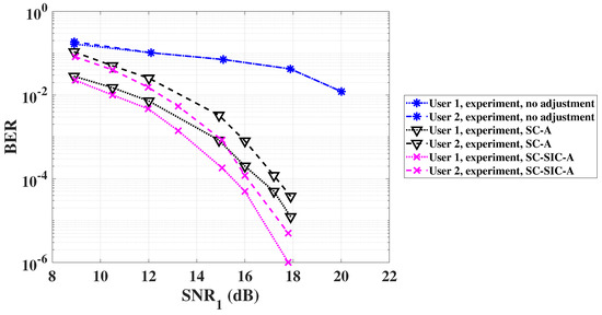
Figure 9.
The experimental BER performance for each user of multi-user NOMA VLC system, when .

Figure 10.
The experimental BER performance for each user of multi-user NOMA VLC system, when .
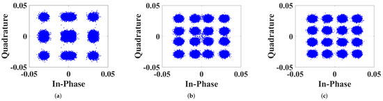
Figure 11.
The SCs of the two-user NOMA VLC system obtained by experiment, when dB. (a) No adjustment scheme; (b) SC-A scheme; (c) SC-SIC-A scheme.

Figure 12.
The SCs of the three-user NOMA VLC system obtained by experiment, when dB. (a) No adjustment scheme; (b) SC-A scheme; (c) SC-SIC-A scheme.
5. Conclusions
In this paper, we propose a joint transceiver optimization scheme to improve BER and the capacity performance of multi-user NOMA VLC systems. This scheme is called SC-SIC-A scheme, where the parameters of SC at the transmitter and the SIC decoding at the receiver are jointly adjusted. We derive closed-form BER expressions under the proposed SC-SIC-A scheme for a multi-user NOMA VLC system. The rule for the number of terms for each user’s BER expression is found, which is named as NOMA triangle regarding the terms of Q-function. Based on the derived BER expressions, we formulate the optimization problem to minimize the average BER for all users by adjusting the parameters of SC and SIC decoding, which is solved by the DE algorithm. We also derive the capacity expressions under the proposed SC-SIC-A scheme. In order to verify the effectiveness and feasibility of the proposed SC-SIC-A scheme, an indoor experiment was carried out. The results of theoretical analysis, MC simulation and experiment match very well, which verifies that the proposed SC-SIC-A scheme can achieve better performance compared with the SC-A scheme in terms of BER and sum capacity performance for multi-user NOMA VLC system. Specifically, for three-user NOMA VLC system, the results show that, compared with SC-A scheme, the SC-SIC-A scheme can reduce SNR to achieve BER of by 5.7 dB, 4.3 dB and 4.6 dB for the three users, respectively, and can reduce SNR to achieve the maximum sum capacity by 1.0 dB. Thus, we recommend that the proposed SC-SIC-A scheme can be widely used for multi-user NOMA VLC systems.
Author Contributions
Conceptualization, T.W. and Z.W.; software, T.W.; validation, T.W., Z.W., S.H., J.Y. and Y.J.; writing—original draft preparation, T.W.; writing—review and editing, Z.W. and S.H.; supervision, Z.W., S.H., J.Y. and Y.J. All authors have read and agreed to the published version of the manuscript.
Funding
This research was supported by the National Natural Science Foundation of China under Grant 61835003.
Institutional Review Board Statement
Not applicable.
Informed Consent Statement
Not applicable.
Data Availability Statement
Not applicable.
Conflicts of Interest
The authors declare no conflict of interest.
Appendix A
Appendix A.1
We take the adjusted SC point at the th column in the first quadrant of Figure 2 as an example to illustrate the derivation of , where of the superposed signal at point is denoted as ‘1’. The distance between point and Q-axis is . When the amplitude of the noise’s horizontal component is larger than , the noisy signal of point in the horizontal direction falls into the region of ‘0’, which is the left side of the Q-axis. Consequently, is detected incorrectly as ‘0’, where the bit error of occurs. Thus, the BER expression of for user 1 at the adjusted SC point can be written as follows [29]:
where is the Q-function. Similarly, the BER for of user 1 at the adjusted SC point in other columns, i.e., to , follows the same principle.
Appendix A.2
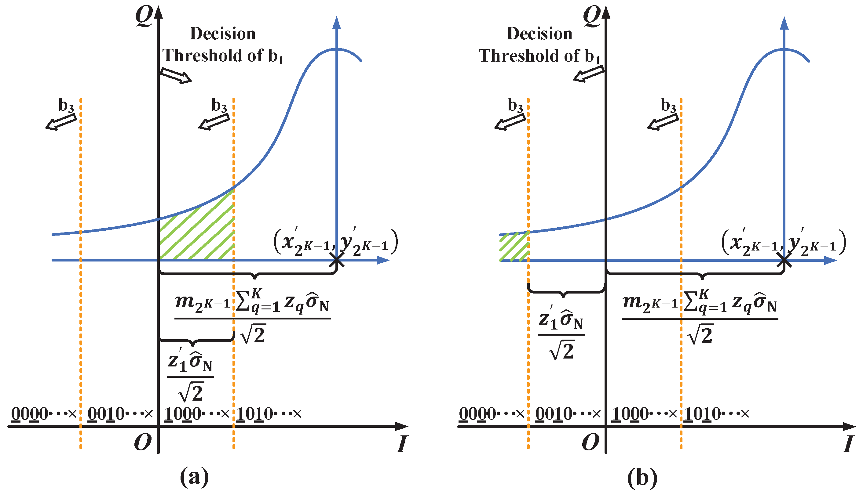
We use Figure A1 to illustrate the derivation of user 2’s BER explicitly. In Figure A1, we take the adjusted SC point as an example, for which its bit sequence is denoted as ‘1010’. In the horizontal direction, the detection result of for user 1 affects its detection of for user 2. The condition that user 1’s is detected correctly is shown in Figure A1a. When the scale of noise’s horizontal component is smaller than , of user 1 is detected correctly. The corresponding decision threshold of is the Q-axis, and is detected as ‘1’ when the noisy superposed NOMA signal falls into the right side of Q-axis. Similarly, when or , the noisy signal of adjusted SC point in the horizontal direction falls into the region that ‘0’, which results in the erroneous detection of . The decision thresholds of are denoted by the yellow dotted lines in Figure A1a, and the decision regions where is detected wrongly are the left side of the yellow dotted lines in the corresponding quadrants. The area of shaded region in Figure A1a is the error probability of . Thus, the BER expression of for user 2 at adjusted SC point under the condition that of user 1 is detected correctly is given by the following:
where . The condition that of user 1 is detected wrongly is shown in Figure A1b. Following the same principle as that depicted in Figure A1a, the area of shaded region in Figure A1b is the error probability of for user 2 at adjusted SC point under the condition that user 1 is detected wrongly, and the corresponding BER expression is as follows.
Since the of user 2 at the adjusted SC point in the rest columns follows the same principle to derive its BER expression, the BER of user 2 can be obtained according to Equation (10).
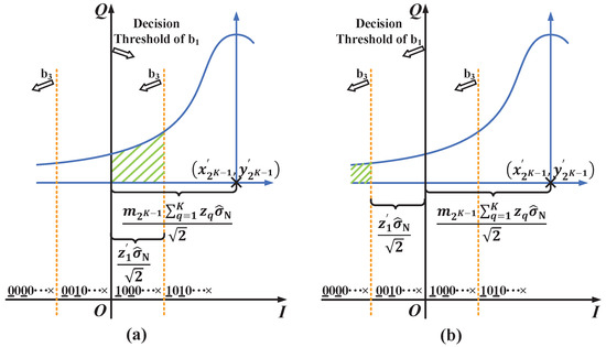
Figure A1.
The constellations of the adjusted SC point for deriving in K-user NOMA VLC system. (a) User 1 is detected correctly and (b) user 1 is detected incorrectly.
Figure A1.
The constellations of the adjusted SC point for deriving in K-user NOMA VLC system. (a) User 1 is detected correctly and (b) user 1 is detected incorrectly.
Appendix A.3
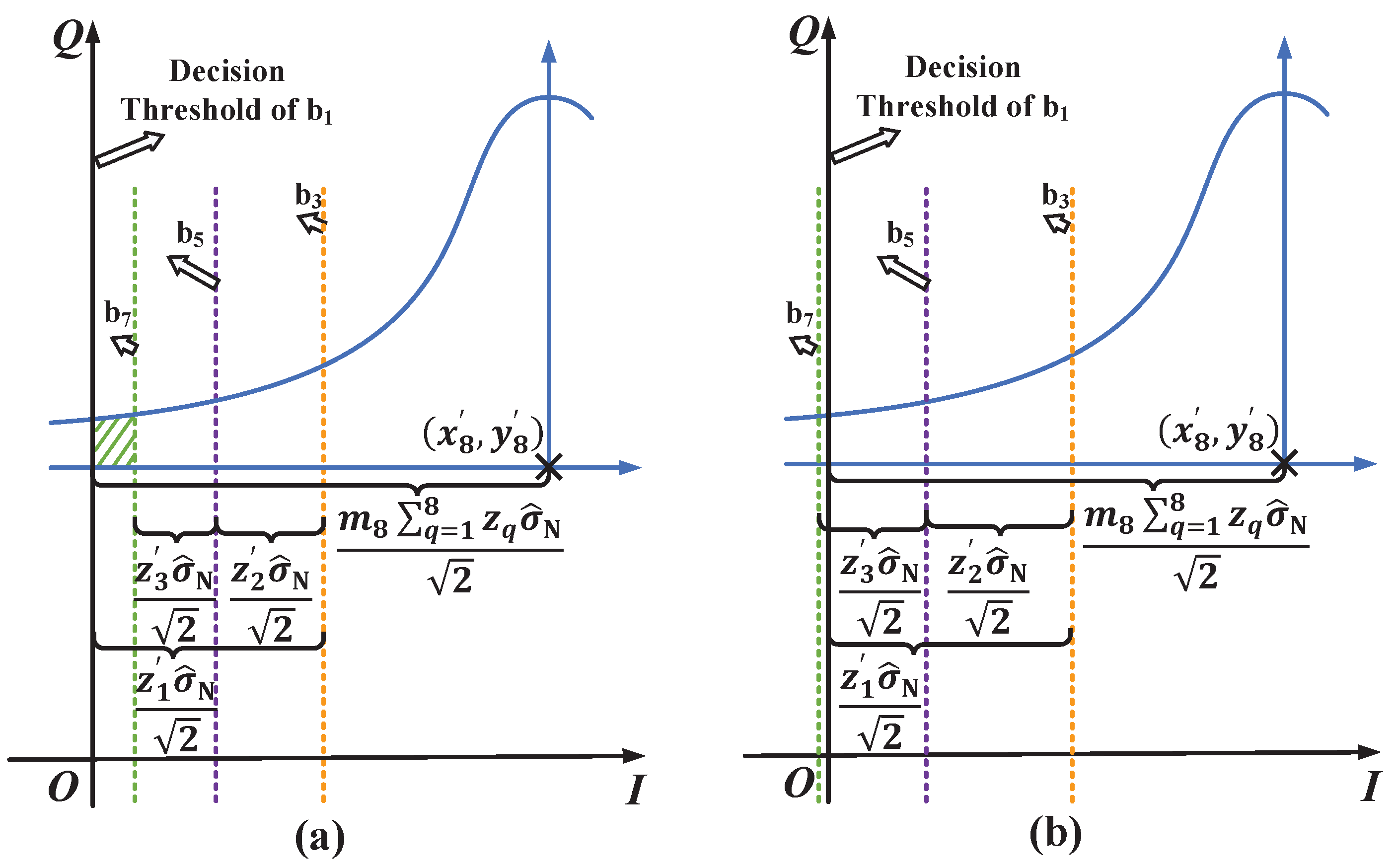
Under the condition that the bit of user 1 is detected correctly and the bits of user 2 and user 3 are detected incorrectly to derive the BER expression of user 4, we take the adjusted SC point in first quadrant as an example to explain the special cases affected by SIC decoding parameters, which are shown in Figure A2. The bit sequence of the adjusted SC point is denoted as . In the horizontal direction, the detection results of the first bit for user 1, user 2 and user 3 affect the detection of for user 4. Following the derivation principles of user 2’s BER expression, the decision thresholds of , , and are the Q-axis, orange dotted line, purple dotted line and green dotted line in Figure A2, respectively. Regions that is detected correctly and , as well as are detected incorrectly are the right side of Q-axis and the left side of all dotted lines in the corresponding quadrants, respectively. The area of the part where the decision regions of , , and overlap is affected by , and . The case that is called Case I, which is illustrated in Figure A2a. From the constellation of the adjusted SC point under Case I, we can find that the area of shaded region is the error probability of for user 4. Thus, the BER expression under Case I is given by the following.
The case where is called Case II, which is illustrated in Figure A2b.We can find that the overlapping part of the decision regions of , , and do not exist. Thus, there is no bit error under the Case II, i.e., the BER expression under Case II is zero. Note that let in Equation (A4) be zero, the BER expression Equation (A4) under Case I is changed to that under Case II. Thus, the BER expression under Case II can be written as follows.
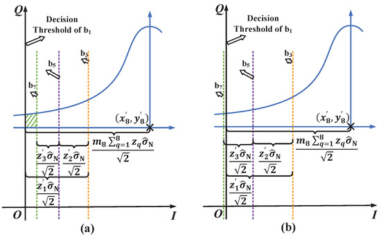
Figure A2.
The constellations of the adjusted SC point for deriving BER expression of user 4 in four-user NOMA VLC system. (a) The constellation of Case I and (b) the constellation of Case II.
Figure A2.
The constellations of the adjusted SC point for deriving BER expression of user 4 in four-user NOMA VLC system. (a) The constellation of Case I and (b) the constellation of Case II.
References
- Yang, H.; Alphones, A.; Zhong, W.; Chen, C.; Xie, X. Learning-Based Energy-Efficient Resource Management by Heterogeneous RF/VLC for Ultra-Reliable Low-Latency Industrial IoT Networks. IEEE Trans. Ind. Inform. 2020, 16, 5565–5576. [Google Scholar] [CrossRef]
- Al Hammadi, A.; Sofotasios, P.C.; Muhaidat, S.; Al-Qutayri, M.; Elgala, H. Non-Orthogonal Multiple Access for Hybrid VLC-RF Networks with Imperfect Channel State Information. IEEE Trans. Veh. Technol. 2021, 70, 398–411. [Google Scholar] [CrossRef]
- Karunatilaka, D.; Zafar, F.; Kalavally, V.; Parthiban, R. LED Based Indoor Visible Light Communications: State of the Art. IEEE Commun. Surv. Tutor. 2015, 17, 1649–1678. [Google Scholar] [CrossRef]
- Liu, X.; Wang, Y.; Zhou, F.; Ma, S.; Hu, R.Q.; Ng, D.W.K. Beamforming Design for Secure MISO Visible Light Communication Networks with SLIPT. IEEE Trans. Commun. 2020, 68, 7795–7809. [Google Scholar] [CrossRef]
- Obeed, M.; Dahrouj, H.; Salhab, A.M.; Zummo, S.A.; Alouini, M.S. User Pairing, Link Selection, and Power Allocation for Cooperative NOMA Hybrid VLC/RF Systems. IEEE Trans. Wirel. Commun. 2021, 20, 1785–1800. [Google Scholar] [CrossRef]
- Pathak, P.H.; Feng, X.; Hu, P.; Mohapatra, P. Visible Light Communication, Networking, and Sensing: A Survey, Potential and Challenges. IEEE Commun. Surv. Tutor. 2015, 17, 2047–2077. [Google Scholar] [CrossRef]
- Chen, C.; Zhong, W.D.; Yang, H.; Du, P. On the Performance of MIMO-NOMA-Based Visible Light Communication Systems. IEEE Photon. Technol. Lett. 2018, 30, 307–310. [Google Scholar] [CrossRef]
- Shi, J.; He, J.; Wu, K.; Ma, J. Enhanced Performance of Asynchronous Multi-Cell VLC System Using OQAM/OFDM-NOMA. J. Lightw. Technol. 2019, 37, 5212–5220. [Google Scholar] [CrossRef]
- Janjua, M.B.; da Costa, D.B.; Arslan, H. User Pairing and Power Allocation Strategies for 3D VLC-NOMA Systems. IEEE Wirel. Commun. Lett. 2020, 9, 866–870. [Google Scholar] [CrossRef]
- Wang, G.; Shao, Y.; Chen, L.K.; Zhao, J. Subcarrier and Power Allocation in OFDM-NOMA VLC Systems. IEEE Photon. Technol. Lett. 2021, 33, 189–192. [Google Scholar] [CrossRef]
- Dai, L.; Wang, B.; Ding, Z.; Wang, Z.; Chen, S.; Hanzo, L. A Survey of Non-Orthogonal Multiple Access for 5G. IEEE Commun. Surv. Tutor. 2018, 20, 2294–2323. [Google Scholar] [CrossRef] [Green Version]
- Shi, J.; Hong, Y.; Deng, R.; He, J.; Chen, L.K.; Chang, G.K. Demonstration of Real-Time Software Reconfigurable Dynamic Power-and-Subcarrier Allocation Scheme for OFDM-NOMA-Based Multi-User Visible Light Communications. J. Lightw. Technol. 2019, 37, 4401–4409. [Google Scholar] [CrossRef]
- Qiu, H.; Gao, S.; Tu, G. An Opportunistic NOMA Scheme for Multiuser Spatial Multiplexing VLC Systems. IEEE Commun. Lett. 2021, 25, 3017–3021. [Google Scholar] [CrossRef]
- Ding, Z.; Lei, X.; Karagiannidis, G.; Schober, R.; Yuan, J.; Bhargava, V. A Survey on Non-Orthogonal Multiple Access for 5G Networks: Research Challenges and Future Trends. IEEE J. Sel. Areas Commun. 2017, 35, 2181–2195. [Google Scholar] [CrossRef] [Green Version]
- Liu, Y.; Qin, Z.; Elkashlan, M.; Ding, Z.; Nallanathan, A.; Hanzo, L. Nonorthogonal Multiple Access for 5G and Beyond. Proc. IEEE 2017, 105, 2347–2381. [Google Scholar] [CrossRef] [Green Version]
- Islam, S.M.R.; Avazov, N.; Dobre, O.A.; Kwak, K.S. Power-Domain Non-Orthogonal Multiple Access (NOMA) in 5G Systems: Potentials and Challenges. IEEE Commun. Surv. Tutor. 2017, 19, 721–742. [Google Scholar] [CrossRef] [Green Version]
- Almohimmah, E.M.; Alresheedi, M.T. Error Analysis of NOMA-Based VLC Systems with Higher Order Modulation Schemes. IEEE Access 2020, 8, 2792–2803. [Google Scholar] [CrossRef]
- Liu, X.; Chen, Z.; Wang, Y.; Zhou, F.; Luo, Y.; Hu, R.Q. BER Analysis of NOMA-Enabled Visible Light Communication Systems with Different Modulations. IEEE Trans. Veh. Technol. 2019, 68, 10807–10821. [Google Scholar] [CrossRef]
- Guan, X.; Yang, Q.; Hong, Y.; Chan, C.C.K. Non-orthogonal multiple access with phase pre-distortion in visible light communication. Opt. Express 2016, 24, 25816–25823. [Google Scholar] [CrossRef]
- Ren, H.; Wang, Z.; Du, S.; He, Y.; Chen, J.; Han, S.; Yu, C.; Xu, C.; Yu, J. Performance improvement of NOMA visible light communication system by adjusting superposition constellation: A convex optimization approach. Opt. Express 2018, 26, 29796–29806. [Google Scholar] [CrossRef] [Green Version]
- Marshoud, H.; Sofotasios, P.; Muhaidat, S.; Karagiannidis, G.; Sharif, B. On the Performance of Visible Light Communication Systems with Non-Orthogonal Multiple Access. IEEE Trans. Wirel. Commun. 2017, 16, 6350–6364. [Google Scholar] [CrossRef] [Green Version]
- Du, C.; Ma, S.; He, Y.; Lu, S.; Li, H.; Zhang, H.; Li, S. Nonorthogonal Multiple Access for Visible Light Communication IoT Networks. Wirel. Commun. Mob. Com. 2020, 2020, 1–10. [Google Scholar] [CrossRef]
- Wu, T.; Wang, Z.; Yu, J.; Han, S.; Jiang, Y. Joint Transceiver Optimization for Performance Improvement of Multi-User NOMA VLC System. In Proceedings of the 2021 IEEE 21th International Conference on Communication Technology (ICCT), Tianjin, China, 13–16 October 2021; pp. 1477–1481. [Google Scholar]
- Yin, L.; Popoola, W.; Wu, X.; Haas, H. Performance Evaluation of Non-Orthogonal Multiple Access in Visible Light Communication. IEEE Trans. Commun. 2016, 64, 5162–5175. [Google Scholar] [CrossRef] [Green Version]
- Komine, T.; Nakagawa, M. Fundamental analysis for visible-light communication system using LED lights. IEEE Trans. Consum. Electron. 2004, 50, 100–107. [Google Scholar] [CrossRef]
- Price, K.; Storn, R.; Lampinen, J. Differential Evolution: A Practical Approach to Global Optimization; Springer: Berlin/Heidelberg, Germany, 2005. [Google Scholar]
- Baig, S.; Ali, U.; Asif, H.M.; Khan, A.A.; Mumtaz, S. Closed-Form BER Expression for Fourier and Wavelet Transform-Based Pulse-Shaped Data in Downlink NOMA. IEEE Commun. Lett. 2019, 23, 592–595. [Google Scholar] [CrossRef]
- Assaf, T.; Al-Dweik, A.; Moursi, M.E.; Zeineldin, H. Exact BER Performance Analysis for Downlink NOMA Systems Over Nakagami-m Fading Channels. IEEE Access 2019, 7, 134539–134555. [Google Scholar] [CrossRef]
- Wang, X.; Labeau, F.; Mei, L. Closed-Form BER Expressions of QPSK Constellation for Uplink Non-Orthogonal Multiple Access. IEEE Commun. Lett. 2017, 21, 2242–2245. [Google Scholar] [CrossRef]


Publisher’s Note: MDPI stays neutral with regard to jurisdictional claims in published maps and institutional affiliations. |
© 2022 by the authors. Licensee MDPI, Basel, Switzerland. This article is an open access article distributed under the terms and conditions of the Creative Commons Attribution (CC BY) license (https://creativecommons.org/licenses/by/4.0/).