Abstract
We present a new scheme of picosecond optical parametric chirped pulse amplification (OPCPA) in which a Fourier-transform-limit 5.0 ps pulse is optically sheared from a single-longitudinal-mode 1064 nm CW laser. The pulse is amplified and frequency-doubled as the pump in order to maintain the pump narrow bandwidth and picosecond duration simultaneously, which is very important to ensure the high temporal contrast for an OPCPA amplifier. Combined with the cross-polarized wave generation (XPW), a compound frontend for the high-power femtosecond laser system that delivers a 1 Hz chirped pulse train is established. The experiments provide an output pulse energy of 17.1 mJ, a spectrum bandwidth 71 nm (FWHM), and a pulse duration 16.4 fs. The pulse contrast reaches 1:10−12 several picoseconds before the peak of the main pulse, which is the best value of the available measuring instruments.
1. Introduction
Petawatt-scale femtosecond lasers are essential tools for research on high-energy-density physics, laser plasma interactions, secondary light sources, and laboratory astrophysics. Since the demonstration of the first petawatt-scale laser [1,2], the duration of the laser pulse has been reduced from a few picoseconds to several tens of femtoseconds, and many global laboratories are now dedicated to the development of petawatt-scale femtosecond lasers. To date, nearly 200 ultrafast lasers have been completed, are under construction, or are being scheduled. An example of this is the ELI project, which involves 13 European countries and intends to build three 10 PW pillars: ELI-NP in Romania [3,4], ELI-Beamlines in Czech Republic [5], and Eli-Alps in Hungary [6]. Other multi-petawatt lasers, such as Vulcan-10 PW in Britain and PEARL-10PW in Russia [7,8], are designed to use an optical parametric chirped pulse amplification technique to deliver 300 J, 30 fs pulses in single-shot mode; Apollon-10PW in France is designed to use a chirped pulse amplification (CPA) technique to deliver 150 J [9,10,11], 15 fs pulses; and OPAL, a femtosecond beamline with peak power of 75 PW apart from the OMEGA-EP (extended performance) picosecond beamlines, is proposed at the University of Rochester [12]. In addition, there are three multi-petawatt pillars under construction in China: the SG-II 5PW laser is an OPCPA system that has committed 1.76 PW, 21 fs pulses since 2016 [13,14]; the CAEP-5PW in Sichuan province has reported 4.9 PW peak power and been run at 1 PW level since 2018 [15]; and in the same year, SULF-10PW in the Shanghai Institute of Optics and Fine Mechanics (SIOM) demonstrated chirped pulse energy over 190 J and the ability to bear 5 PW outputs [16]. In Korea, a 4.2 PW CPA system has been reported, which operates at a petawatt level [17,18]. Petawatt lasers such as the above are large-scale engineering tasks, usually composed of three parts: a millijoule-level frontend, a hundred-joule-level amplification bay, and a terminal unit composed of a compressor, a target chamber, a vacuum set, and a diagnostics suite. Before the output laser pulses are directed onto the target, techniques should be employed to ensure high beam quality in achieving a diffraction-limited focal spot and a high contrast ratio to avoid the vaporization of the target surface by pre-pulse. As the first loop of the whole petawatt laser system, the frontend has been studied and various setups have been constructed by many laboratories.
By using OPCPA in nonlinear crystals with broad parametric gain bandwidth, there has been significant progress in developing femtosecond high-power laser systems [19]. The peak power of first PW-class OPCPA femtosecond laser system is 0.56 PW peak power, which is based on high-energy amplification in large deuterated potassium dihydrogen phosphate (DKDP) crystals [8]. A single-shot 4.9 PW femtosecond laser system, by using low-energy picosecond OPCPA in BBO crystals and high-energy nanosecond OPCPA in large lithium triborate (LBO) crystals in the 800 nm spectral bandwidth, with less than 20 fs amplified pulse duration and high-intensity contrast, has been reported [15]. Moreover, several 100 PW femtosecond laser projects, based on high-energy noncollinear OPCPA, have been proposed [20]. In our work, we construct a frontend using a novel optically synchronized picosecond OPCPA scheme combined with a cross-polarized wave-generation (XPW) technique. The characteristic of this method is that, in contrast to methods in the literature, it involves specializing a sub-10-picosecond and a narrow band pulse as the OPCPA pump to improve the contrast ratio at 10 ps before the main pulse. The reason is that for the interaction between femtosecond laser pulses and the target, the process usually experiences three phases: (1) the 100 fs phase, where photons are absorbed by electrons; (2) the 1.0 ps phase, where energy is transferred from electrons to the lattice of the target; and (3) the 10 ps phase, where energy is transferred from the lattice to the inner part of the target and then the target is destroyed. If the intensity of the pre-pulse (10 ps before the main pulse) is too high to destroy the target, then the physical experiment fails.
As the focused laser intensity has now reached 1022 W/cm2, the requirements for temporal contrast should be higher than 1:10−11, which entails the intensity of the pre-pulse not exceeding 1012 W/cm2. Many techniques to improve the pulse contrast have been developed and used in different parts of the petawatt lasers. A plasma mirror has been placed at the target area to steepen the edge of the focused laser pulses [21]. In the nanosecond OPCPA regime, the spatial and temporal profile matching between the signal and pump are carefully maintained to decrease the fluorescence during the amplification process. For seed pulses, saturable absorbers [22], self-diffraction [23], XPW [24], and picosecond optical parametric amplification are usually combined to achieve a contrast ratio as high as 1:10−11 [11,22,25,26,27,28,29]. It has been assumed that by using a picosecond OPCPA, the pulse contrast can be improved by as much as five orders of magnitude. In general, there are two ways of exactly synchronizing the pump pulse with the signal pulse in the picosecond OPCPA regime. One way described in ref uses a single femtosecond seed and splits it into two parts [30]: one used as the signal and the other, amplified and frequency-doubled, as the pump, in which both the pump and the signal are broadband. However, from reference [31] we see that the broadband pump pulse can result in a higher amplified spontaneous emission (ASE) base to the signal. However, the chirp carried by the pump pulse can induce an extra nonlinear chirp to the signal and cause the pulse contrast to degenerate. Another way uses a narrowband laser pulse as the pump and splits a portion of it; the portion is used to generate a supercontinuum to form the seed pulse. In this way, it can produce a spectrum width of more than 400 nm and a narrowest pulse duration of approximately 11 fs [32]. In fact, this resume usually uses pulses of several tens or hundreds of picoseconds as the pump. This is not a real picosecond OPCPA; the contrast ratio 10 ps before the pulse peak be only improved effectively when the width of the pump pulse is no more than 10 ps. As mentioned in the previous paragraph, the intensity of the pre-pulse 10 ps before the main pulse should not be high enough to form a plasma jet to destroy the target. In obtaining a sub-10-picosecond pump pulse with a narrow bandwidth, we propose a novel picosecond OPCPA scheme in which pump and signal pulses originate from separate oscillators and are synchronized through a totally optical approach. The experimental results show that, as a frontend subsystem, it is suitable for petawatt-scale lasers, and the temporal pulse contrast ratio is better than 1:10−12.
2. Experimental Setup and Results
Figure 1 shows the setup of the high-contrast frontend seed system for the petawatt-scale laser system. It commits at 1 Hz, determined by the repetition rate of the pump source. At first, the femtosecond pulse train from a commercial femtosecond oscillator (Synergy, 7 fs, 500 mW, 80 MHz, 800 nm) is stretched into 250 ps (chirp rate 2.0 ps/nm) by an Offner stretcher and passes through a two-end-pumped regenerative amplifier pumped by two 50 mJ, 532 nm, and 6.0 ns pulses. The regenerative amplifier also plays the role of a repetition rate selector. After amplification, the energy of the chirped pulse is increased to nearly 3.2 mJ and extracted from the cavity by an optical switch composed of a polarizer (P1) and a Pockels cell (PC1). Another Pockels cell (PC2) lines with P2 and P3 is used to enhance the pulse contrast after the regenerative amplifier. Thereafter, the chirped pulse passes through a double-pass grating-pair compressor (total efficiency ~65%), by which the width is compressed to 5.0 ps and the pulse energy measured to 2.1 mJ. This 1 Hz pulse train will be used as the original pulse for the entire frontend system.
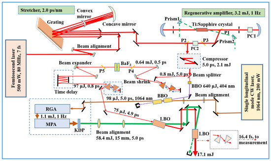
Figure 1.
Schematic of optically synchronized frontend for petawatt-scale laser. P1–P5, polarizers; PC1–PC2, Pockels cells; RGA, regenerative amplifier; and MPA, master power amplifier.
At first, the XPW technique is utilized to steepen the pulse edge and eliminate the sparkles on the pulse-step in our scheme. As shown in Figure 1, after passing through the double-pass compressor, a beam splitter is adopted and splits the 5.0 ps pulse train into two parts. The first part weighs 40% of the energy used as the seed for cascading amplification. A double-pass group-velocity-dispersion compensator is made of a prism pair and an XPW filter that consists of two cross-placed polarizers (P4 and P5), two reflective telescopes, and two BaF2 nonlinear crystals. After the compensator, the pulse energy is reduced to approximately 0.64 mJ and the temporal width is compressed from 5.0 ps to 30 fs, close to the limit of the Fourier transformation. The entire XPW filter is placed in air. The cut orientations of the two BaF2 crystals are all [11], and the thicknesses are set at 1.0 mm and 1.5 mm, respectively. The total efficiency of the XPW filter is approximately 15% (after P5). Because the spectrum of the laser pulse will be broadened by the third-order nonlinear process after the BaF2 crystals, the pulse width of the XPW filter is narrowed from 30 fs to nearly 21 fs, as tested by an auto-correlation trace. Subsequently, it is injected into a time delay unit, which is an eight-pass geometry setup and provides nearly 90 ns retardation with fluctuations of ±1 wavelength (~7 fs) to maintain a seed pulse optically synchronized with the pump pulse at the two consequent lithium triborate (LBO) crystals (the whole front-end system is settled on a vibration-damped table to maintain a stable experimental setting). Subsequently, another double-pass prism-pair is used to stretch the pulse width from 21 fs to approximately 4.9 ps and the final output energy is approximately 75 µJ.
To form a narrowband sub-10-picosecond pulse for the pump of the picosecond OPCPA system, we used a single-longitudinal-mode Nd-doped YAG continuous-wave (CW) laser as the seed pulse; the other portion of the 808 nm centered pulse train (5.0 ps, 1.3 mJ), which comprised 60% of the energy from the beam splitter, frequency-doubled by a type I phase-matching barium borate (BBO) crystal, was utilized to shear the sub-10-picosecond pulse from this origin. The thickness of the BBO crystal was set to 0.8 mm to ensure the highest conversion efficiency, and the second-harmonic generation (SHG) energy obtained was nearly 640 µJ per pulse. In the following optical parametric amplifier (OPA) process, this SHG pulse train (404 nm) is used as the pump, and the preceding single-longitudinal-mode CW laser as the signal. The OPA uses two pieces of BBO crystals (18 mm for each) as the gain media. After the second BBO crystal, a 5.0 ps, 1064 nm pulse train is sheared from the CW laser beam, and the energy is amplified from 0.6 pJ to approximately 98 µJ with an estimated gain of 108. Considering that linewidth of the Nd:YAG crystal at 1064 nm is nearly 0.45 nm, which means its Fourier transform limit is probably 3.7 ps for a Gaussian profile, it is certain that 5.0 ps is a reasonable value that fulfills not only the requirements of the narrow band but also the requirements of the sub-10-picosecond pulse for a picosecond OPCPA design. Figure 2a shows the calculations of phase matching of the BBO crystal in the OPA process by a 404 nm broadband pump and 1064 nm narrowband signal. We see that it is very promising when the phase-matching angle ranges from 28° to 30°. On this occasion, we select the non-collinear angle (alpha in Figure 2) as 3° and the phase-matching angle of BBO crystal as 28.6°. To boost the energy of the sheared pump pulse, it is then injected into a homemade regenerative amplifier and being operated at 1 Hz repetition. After that, the pulse energy is amplified to 1.1 mJ. The beam size is expanded to 15 mm and enters two consecutive flash-pumped four-pass Nd:YAG master amplifiers. The first four-pass amplifier achieves a total gain of approximately 22 times and outputs a pulse energy of approximately 24 mJ. The second four-pass amplifier uses a concave lens (focal length −25 m) and a six-element deformable mirror to compensate for the wavefront distortion caused by the thermal effect. It boosts the energy of the sheared pulse to approximately 85 mJ. To suppress the self-focusing effect of both amplifiers, two negative-nonlinear-refractive-index GaAs plates (thickness of 0.3 mm) are adopted, and each is inserted into a four-pass amplifier to compensate for the positive nonlinear refractive index of the Nd:YAG rods. Assuming that the amplification is saturable and that the laser intensity is proportional to the length of the gain media, then the B-integral for a Nd:YAG rod in a four-pass amplifier should be,
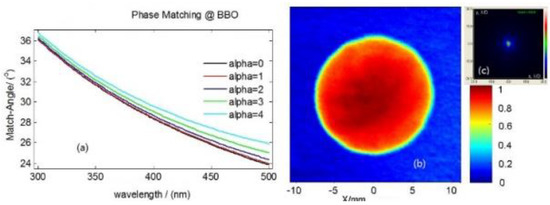
Figure 2.
Calculations of phase-matching angle of the BBO crystal at 404 nm and 1064 nm (a); spatial profile of the sheared pump pulse (1064 nm) (b); far-field distribution of the sheared pump pulse (1064 nm) (c).
For a GaAs plate set before the gain media,
where is the wavelength; and L are the nonlinear refractive index and length of the two Nd:YAG rods, and ; and the input and output laser intensities, respectively, and , represent the nonlinear refractive index and the thickness of the two GaAs plates. By substituting , [31], , and into Equations (1) and (2); and for the first amplifier; and and for the second, the summation of the B-integral is calculated as approximately 0.02 and 0.09 for the first and second four-pass amplifier, respectively. The pulse-to-pulse stability of the energy has been measured as less than 7% and is mainly determined by the fluctuations of the pump flash lamps and regenerative amplifiers. Figure 2b,c show the near- and far-field distributions of the beam out of the last four-pass amplifier, respectively, and the Strehl ratio is approximately 0.7, close to the limit of diffraction. Finally, this sheared pulse is frequency-doubled by a potassium dihydrogen phosphate (KDP) crystal (thickness 12 mm). Subsequently, a 5.0 ps green pulse train (532 nm) with a pulse energy of approximately 58.4 mJ is obtained and optically synchronized with the previous 808 nm centered chirped seed pulse at an accuracy of a few femtoseconds.
This green pulse is then used as the pump for a picosecond OPCPA. It undergoes a spatial filter as an imaging relay transferred to maintain a high-quality near-field distribution at the position of the last nonlinear crystal of the picosecond OPCPA setup, which consists of two cascaded type-I LBO crystals arranged in an L-structure to avoid the idle beam reentering the second LBO crystal. The cut orientation of the two LBO crystals is and , the angles between the pump and the signal at both crystals are set at 1.16°, and the lengths of the two crystals are chosen as 8 mm and 6 mm, respectively. By evaluation, the pump power density at the first crystal is 6.6 GW/cm2 and that at the second is 5.95 GW/cm2. The experimental results proved that it can be safely operated under these amounts at a pulse duration of 5.0 ps. The maximum efficiency achieved for the entire system is approximately 29%, and the energy of a single pulse measured nearly 17.1 mJ.
3. Discussion and Outlook
The XPW filter and picosecond OPCPA play different roles in the frontend system. Although the XPW can improve the pulse contrast over the full temporal range of the input pulses, our primary concern is to use it to improve the near-peak contrast and lower the on-foot sparkles because the picosecond OPCPA technique is thought to predominantly improve the contrast out of the temporal range of the pump pulse when not considering the amplifying magnifications. Figure 3 shows the contrast ratio measured by a commercial Sequoia. Figure 3a shows the traces of full temporal range contrast taken before and after the XPW filter, sampled at a low scan resolution with a data acquisition rate of 20 MHz (data interval 5 ps). It shows that without the XPW filter, the pulse contrast is ~1:10−8 over a range of 400 ps and reaches 1:10−6 in the close area of the pulse peak by neglecting the pulse sparkles, which are assumed to result from surface multi-reflection of the optical elements. While the pulse passes through the XPW filter, we can see from the blue curve that not only does the amplitude of the sparkles greatly decrease but also the whole contrast ratio ranging from 400 ps to near the pulse peak is constantly kept close to 1:10−10. Figure 3b shows the contrast ratio of the seed pulse measured after the test compressor. By neglecting the multi-reflection sparkles and assuming the contrast ratio of the exterior region of the pump pulse is high enough to neglect at nearly 103 times magnification by the picosecond OPCPA, we then limited the Sequoia scanning range within ±20 ps to ensure a high scanning resolution, a data acquisition rate up to 200 MHz (data interval 0.5 ps), and a better understanding of the output contrast ratio. Thus, we can conclude from Figure 3b that after picosecond OPCPA amplification, the contrast ratio out of the range of 10 ps before the pulse peak is well below 1:10−12, and that from 10 ps to approximately 2 ps near the pulse peak is approximately 1:10−11 to 1:10−10.
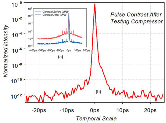
Figure 3.
Pulse contrast ratio measured using Sequoia scanning apparatus. (a) Contrast ratio measured before (red curve) and after (blue curve) the XPW filter; (b) contrast ratio at the end of the entire system.
Figure 4 shows the spectrum measurement results of the entire system. The red curve is the spectrum profile of the seed pulse after chirped pulse amplification by a regenerative amplifier and passage through the grating-pair compressor. Owing to the spectrum-narrowing effect, the interval between the front and rear feet of the pulse is reduced to approximately 70 nm (775–845 nm) from an initial value of more than 100 nm. After the XPW filter, according to the green curve, the FWHM of the spectrum is approximately 60 nm (the foot range is slightly broadened and spans 770–847 nm). Compared with the red curve, Figure 4 shows that the XPW process broadened the spectrum and raised the pulse edges. The blue curve is the spectrum result after the final picosecond OPCPA amplifier. Its foot ranges from 760 nm to 850 nm, and the FWHM is approximately 71 nm. The spectrum width is broadened by the OPCPA process owing to the saturable amplification and wider temporal width of the pump pulse compared with that of the 808 nm centered seed pulse. Because the blue spectral component has always been around but the seed pulse after chirped pulse amplification by a regenerative amplifier, the edge of the spectrum is amplified more than the middle of the spectrum, so the output spectrum is broader than the input, with an additional spectral component in the blue part.
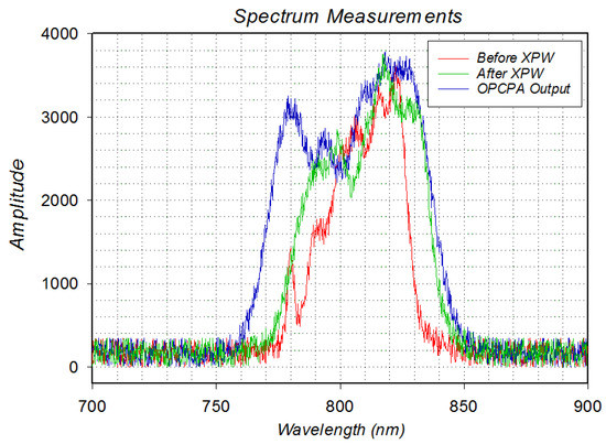
Figure 4.
Spectrum measurements of the frontend laser system. The red, green, and blue curves are the profiles before the XPW filter, after the XPW filter, and out of the final OPCPA amplifier, respectively.
The energy of the seed pulse after the picosecond OPCPA is measured nearly 17.1 mJ. A small portion of the pulse is split out and directed into the test compressor. After compression, it is measured by a single-shot femtosecond auto-correlator. Figure 5 shows an auto-correlation trace obtained by measurement. The resolution is 1 fs, and the width of the laser pulse is approximately 16.4 fs.
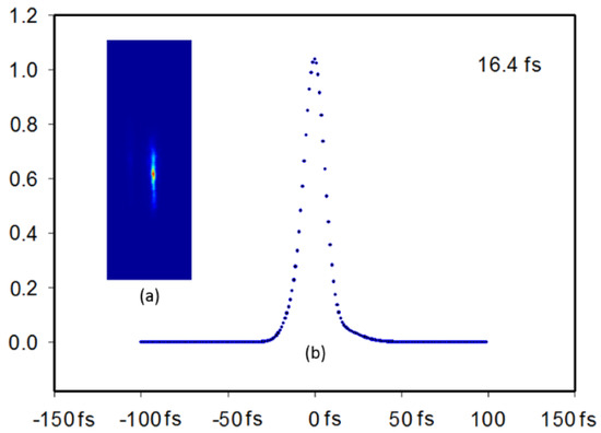
Figure 5.
Auto-correlation trace of the compressed seed pulse by a single-shot femtosecond auto-correlator.
4. Conclusions
In contrast to existing literature on frontend systems for petawatt lasers using the picosecond OPCPA technique, our seeder system achieved a novel way of forming an optically synchronized picosecond pump pulse that not only keeps the width sub-10 picoseconds but also fits the requirement of narrow linewidth. In recent years, several-hundred-petawatt lasers have been proposed or fabricated in various laboratories, with the supposed focused intensity reaching 1025 W/cm2, which means that the pulse contrast ratio must be higher than 1:10−13. This regime, although slightly more complicated, has the potential to realize an even higher contrast ratio frontend because the noise beyond 10 ps of the pulse peak will not be amplified and the pulse can be kept very clean at the same range.
Author Contributions
Conceptualization, X.X., M.S., X.Z. and H.X.; methodology, H.X., X.X., L.Q. and L.L.; software, H.Z., M.S., J.K. and Z.L.; validation, H.X., X.Z., D.Z. and P.Z.; formal analysis, G.Z., Q.Y. and A.G.; investigation, X.L., Q.Y. and A.G.; resources, X.X.; data curation, H.X.; writing—original draft preparation, H.X.; writing—review and editing, H.X.; visualization, H.X.; supervision, X.X. and M.S.; project administration, X.X. and X.Z.; and funding acquisition, X.X. and M.S. All authors have read and agreed to the published version of the manuscript.
Funding
This work was supported by the project of intergovernmental international scientific and technological innovation cooperation by the Ministry of Science and Technology of China (grand number 2021YFE0116700), the projects of National Natural Science Foundation of China (grant number 12074399, 12204500, 12004403), and the projects of the Science and Technology Commission of Shanghai Municipality (grand numbers 22YF1455300 and 20ZR1464400). Foundation of Chinese Academy of Science (Grant Nos. CXJJ-21S015).
Institutional Review Board Statement
Not applicable.
Informed Consent Statement
Not applicable.
Data Availability Statement
Not applicable.
Conflicts of Interest
The authors declare no conflict of interest.
References
- Perry, M.D.; Pennington, D.; Stuart, B.C.; Tietbohl, G.; Brown, J.A.; Herman, S.; Golick, B.; Kartz, M.; Miller, J.; Powell, H.T.; et al. Petawatt laser pulses. Opt. Lett. 1999, 24, 160–163. [Google Scholar] [CrossRef]
- Danson, C.N.; Haefner, C.; Bromage, J.; Butcher, T.; Chanteloup, J.-C.F.; Chowdhury, E.A.; Galvanauskas, A.; Gizzi, L.A.; Hein, J.; Hillier, D.I.; et al. Petawatt and exawatt class lasers worldwide. High Power Laser Sci. Eng. 2019, 7, e54. [Google Scholar] [CrossRef]
- Dabu, R. High power femtosecond lasers at ELI-NP. AIP Conf. Proc. 2015, 1645, 219. [Google Scholar]
- Lureau, F.; Laux, S.; Casagrande, O.; Chalus, O.; Pellegrina, A.; Matras, G.; Radier, C.; Rey, G.; Ricaud, S.; Herriot, S.; et al. Latest results of 10 petawatt laser beamline for ELi nuclear physics infrastructure. Proc. SPIE 2016, 9726, 972613. [Google Scholar]
- Rus, B.; Bakule, P.; Kramer, D.; Naylon, J.; Thoma, J.; Fibrich, M.; Green, J.T.; Lagron, J.C.; Antipenkov, R.; Bartoníček, J.; et al. ELI-Beamlines: Progress in development of next generation short-pulse laser systems. Proc. SPIE 2017, 10241, 102410J. [Google Scholar]
- Kühn, S.; Dumergue, M.; Kahaly, S.; Mondal, S.; Füle, M.; Csizmadia, T.; Farkas, B.; Major, B.; Várallyay, Z.; Cormier, E.; et al. The ELI-ALPS facility: The next generation of attosecond sources. J. Phys. B At. Mol. Opt. Phys. 2017, 13, 132002. [Google Scholar] [CrossRef]
- Hernandez-Gomez, C.; Blake, S.; Chekhlov, O.; Clarke, R.; Dunne, A.; Galimberti, M.; Hancock, S.; Heathcote, R.; Holligan, P.; Lyachev, A.; et al. The vulcan 10 pw project. J. Phys. Conf. Ser. 2010, 244, 32006. [Google Scholar] [CrossRef]
- Lozhkarev, V.; Freidman, G.; Ginzburg, V.; Katin, E.; Khazanov, E.; Kirsanov, A.; Luchinin, G.; Mal’shakov, A.N.; Martyanov, M.A.; Palashov, O.V.; et al. Compact 0.56 petawatt laser system based on optical parametric chirped pulse amplification in KD* P crystals. Laser Phys. Lett. 2007, 4, 421–427. [Google Scholar] [CrossRef]
- Zou, J.P.; Le Blanc, C.; Papadopoulos, D.N.; Ch´eriaux, G.; Georges, P.; Mennerat, G.; Druon, F.; Lecherbourg, L.; Pellegrina, A.; Ramirez, P.; et al. Design and current progress of the Apollon 10 PW project. High Power Laser Sci. Eng. 2015, 3, e2. [Google Scholar] [CrossRef]
- Papadopoulos, D.N.; Zou, J.P.; Le Blanc, C.; Ch´eriaux, G.; Georges, P.; Druon, F.; Mennerat, G.; Ramirez, P.; Martin, L.; Fr´eneaux, A.; et al. The Apollon 10 PW laser: Experimental and theoretical investigation of the temporal characteristics. High Power Laser Sci. Eng. 2016, 4, e34. [Google Scholar] [CrossRef]
- Papadopoulos, D.N.; Ramirez, P.; Genevrier, K.; Ranc, L.; Lebas, N.; Pellegrina, A.; Le Blanc, C.; Monot, P.; Martin, L.; Zou, J.P.; et al. High-contrast 10 fs OPCPA-based frontend for multi-PW laser chains. Opt. Lett. 2017, 42, 3530–3533. [Google Scholar] [CrossRef]
- Meyerhofer, D.D. OMEGA EP OPAL: A Path to a 75-PW Laser System. In Proceedings of the 56th Annual Meeting of the American Physical Society, Division of Plasma Physics, New Orleans, LA, USA, 27–31 October 2014. [Google Scholar]
- Xie, X.; Zhu, J.; Yang, Q.; Kang, J.; Zhu, H.; Guo, A.; Zhu, P.; Gao, Q. Multi Petawatt Laser Design for the SHENGUANG II Laser Facility. Proc. SPIE 2015, 9513, 95130A. [Google Scholar]
- Zhu, J.; Xie, X.; Sun, M.; Kang, J.; Yang, Q.; Guo, A.; Zhu, H.; Zhu, P.; Gao, Q.; Liang, X.; et al. Analysis and Construction Status of SG-Ⅱ 5PW Laser Facility. High Power Laser Sci. Eng. 2018, 6, e29. [Google Scholar] [CrossRef]
- Zeng, X.; Zhou, K.; Zuo, Y.; Zhu, Q.; Su, J.; Wang, X.; Wang, X.; Huang, X.; Jiang, X.; Jiang, D.; et al. Multi-petawatt laser facility fully based on optical parametric chirped-pulse amplification. Opt. Lett. 2017, 42, 2014–2017. [Google Scholar] [CrossRef]
- Chu, Y.; Gan, Z.; Liang, X.; Yu, L.; Lu, X.; Wang, C.; Wang, X.; Xu, L.; Lu, H.; Yin, D.; et al. High-energy large-aperture Ti:sapphire amplifier for 5 PW laser pulses. Opt. Lett. 2015, 40, 5011–5014. [Google Scholar] [CrossRef]
- Sun, J.H.; Lee, H.W.; Yoo, J.Y.; Yoon, J.W.; Lee, C.W.; Yang, J.M.; Son, Y.J.; Jang, Y.H.; Lee, S.K.; Nam, C.H. 4.2 PW, 20 fs Ti:sapphire laser at 0.1 Hz. Opt. Lett. 2017, 42, 2058. [Google Scholar]
- Yoon, J.W.; Jeon, C.; Shin, J.; Lee, S.K.; Lee, H.W.; Choi, I.W.; Kim, H.T.; Sung, J.H.; Nam, C.H. Achieving the laser intensity of 5.5 × 10²² W/cm2 with a wavefront-corrected multi-PW laser. Opt. Express 2019, 27, 20412–20420. [Google Scholar] [CrossRef]
- François, L.; Matras, G.; Chalus, O.; Derycke, C.; Morbieu, T.; Radier, C.; Casagrande, O.; Laux, S.; Ricaud, S.; Rey, G.; et al. High-energy hybrid femtosecond laser system demonstrating 2 × 10 PW capability. High Power Laser Sci. Eng. 2020, 8. [Google Scholar]
- Yu, L.; Xu, Y.; Liu, Y.; Li, Y.; Li, S.; Liu, Z.; Li, W.; Wu, F.; Yang, X.; Yang, Y.; et al. High-contrast front end based on cascaded XPWG and femtosecond OPA for 10-PW-level Ti: Sapphire laser. Opt. Express 2018, 26, 2625–2633. [Google Scholar] [CrossRef]
- Thaury, C.; Quéré, F.; Geindre, J.P.; Levy, A.; Ceccotti, T.; Monot, P.; Bougeard, M.; Réau, F.; d’Oliveira, P.; Audebert, P.; et al. Plasma mirrors for ultrahigh-intensity optics. Nat. Phys. 2007, 3, 424–429. [Google Scholar] [CrossRef]
- Fourmaux, S.; Payeur, S.; Buffechoux, S.; Lassonde, P.; St-Pierre, C.; Martin, F.; Kieffer, J.C. Pedestal cleaning for high laser pulse contrast ratio with a 100 TW class laser system. Opt. Express 2011, 19, 8486–8497. [Google Scholar] [CrossRef]
- Liu, J.; Okamura, K.; Kida, Y.; Kobayashi, T. Temporal contrast enhancement of femtosecond pulses by a self-diffraction process in a bulk Kerr medium. Opt. Express 2010, 18, 22245–22254. [Google Scholar] [CrossRef]
- Chvykov, V.; Rousseau, P.; Reed, S.; Kalinchenko, G.; Yanovsky, V. Generation of 1011 contrast 50 TW laser pulses. Opt. Lett. 2006, 31, 1456–1458. [Google Scholar] [CrossRef]
- Liu, C.; Wang, Z.; Li, W.; Zhang, Q.; Han, H.; Teng, H.; Wei, Z. Contrast enhancement in a Ti:sapphire chirped-pulse amplification laser system with a noncollinear femtosecond optical-parametric amplifier. Opt. Lett. 2010, 35, 3096–3098. [Google Scholar] [CrossRef][Green Version]
- Siddiqui, A.M.; Cirmi, G.; Brida, D.; Kärtner, F.X.; Cerullo, G. Generation of <7 fs pulses at 800 nm from ablue-pumped optical parametric amplifier at degeneracy. Opt. Lett. 2009, 34, 3592–3594. [Google Scholar]
- Huang, Y.; Zhang, C.; Xu, Y.; Li, D.; Leng, Y.; Li, R.; Xu, Z. Ultrashort pulse temporal contrast enhancement based on noncollinear optical-parametric amplification. Opt. Lett. 2011, 36, 781–783. [Google Scholar] [CrossRef]
- Chalus, O.; Pellegrina, A.; Ricaud, S.; Casagrande, O.; Derycke, C.; Soujaeff, A.; Rey, G.; Radier, C.; Matras, G.; Boudjemaa, L.; et al. High contrast broadband seeder for multi-PW laser system. Proc. SPIE 2016, 9726, 972611, Solid State Lasers XXV: Technology and Devices, (16 March 2016). [Google Scholar] [CrossRef]
- Diouf, M.; Lin, Z.; Harling, M.; Toussaint, K.C., Jr. Demonstration of speckle resistance using space–Time light sheets. Sci. Rep. 2022, 12, 1–7. [Google Scholar] [CrossRef]
- Wang, Y.-H.; Pan, X.; Li, X.-C.; Lin, Z.-Q. Optimization of Pulse Temporal Contrast in Optical Parametric Chirped Pulse Amplification. Chin. Phys. Lett. 2009, 26, 24211. [Google Scholar]
- Indra, L.; Batysta, F.; Hříbek, P.; Novák, J.; Hubka, Z.; Green, J.T.; Antipenkov, R.; Boge, R.; Naylon, J.A.; Bakule, P.; et al. Picosecond pulse generated supercontinuum as a stable seed for OPCPA. Opt. Lett. 2017, 42, 843–846. [Google Scholar] [CrossRef]
- Lv, S.; Lu, S.; Chen, M. Suppressing self-focusing effect in high peak power Nd: YAG picosecond Laser amplifier system. Infrared Laser Eng. 2019, 48, 69–76. [Google Scholar]
Publisher’s Note: MDPI stays neutral with regard to jurisdictional claims in published maps and institutional affiliations. |
© 2022 by the authors. Licensee MDPI, Basel, Switzerland. This article is an open access article distributed under the terms and conditions of the Creative Commons Attribution (CC BY) license (https://creativecommons.org/licenses/by/4.0/).