Article

Design of Hybrid Fractal Integrated Half Mode SIW Band Pass Filter with CSRR and Minkowski Defected Ground Structure for Sub-6 GHz 5G Applications

by
Nitin Muchhal
1,*,
Mostafa Elkhouly
1,
Renato Zea Vintimilla
1,
Arnab Chakraborty
2 and
Shweta Srivastava
2
1
Fraunhofer Institute for Integrated Circuits IIS, Am Wolfsmantel 33, 91058 Erlangen, Germany
2
Jaypee Institute of Information Technology, Noida 201309, India
*
Author to whom correspondence should be addressed.
Photonics 2022, 9(12), 898; https://doi.org/10.3390/photonics9120898
Submission received: 8 October 2022 / Revised: 18 November 2022 / Accepted: 21 November 2022 / Published: 24 November 2022

Abstract

:
A compact and wide-stop band half mode substrate integrated waveguide (HMSIW) filter, incorporated with a hybrid fractal on the upper plane and a complementary split ring resonator (CSRR), along with a defected ground structure (DGS) etched on the bottom plane, is proposed for 5G sub-6 GHz application. A CSRR reduces the resonant frequency causing size miniaturisation by approximately 40% by augmenting the equivalent inductance and capacitance of the CSRR. Further, the low-pass characteristics of the DGS aid in suppressing out-of-band spurious harmonics. A two-pole band pass filter (BPF) is fabricated using FR4 (flame retardant) to validate the design. The results confirm that the proposed filter has a pass band from 3.75 GHz–5.12 GHz with spurious response below −20 dB > 4f0.

1. Introduction

The need for low latency and faster data transfer has grown dramatically with the expeditious development of wireless communication systems. The fifth-generation (5G) communication infrastructure makes it possible to handle innovative deployment setups and industry automation with more capacity and coverage [1]. Massive MIMO systems are successfully maintained by 5G technology, which also upsurges transmission speed. A spectrum lower than 6 GHz, especially around 4.8 GHz, is in boundless demand worldwide for numerous commercial 5G applications [2]. Additionally, fast and unswerving communication services with increased network capability are the goals of the 5G mobile communication, which operates in the sub-6 GHz frequency spectrum.
The Substrate Integrated Waveguide (SIW) technique, however, has plentiful merits over conventional waveguide and microstrip techniques. Some of the merits are: easy unification with planar design, high quality factor, better power handling, etc., although it has a significant drawback in the form of a wider width [3]. Therefore, one of the major issues is the dwindling of the SIW geometry. In [4], the authors reviewed several SIW miniaturisation methods. Compact band pass filters for the X and Ku/K bands using folded SIW technology have been proposed by the authors of [5,6]. In [7], the authors designed a compact selective band pass filter for the X band using an S-shaped broadside coupled CSRR. Recently, the authors of [8] developed a small and broadband SIW band pass filter using the Multimode Resonator (MMR) technique.
Further, in recent times, several researchers have reported the design of SIW band pass filters for 5G communication using several techniques. Yang et al. [9] proposed the concept of the FSIW–CRLH transmission structure. Based on the proposed FSIW–CRLH structure, two partial H-plane filters were designed to substantiate the performance of BPFs. Wong et al. [10] proposed a fourth-order quasi-elliptic SIW filter with centre frequency 3.7 GHz using a slot-coupling technique and a non-adjacent cross-coupling method. Duraisamy et al. [11] designed a miniaturized SIW band pass filter with a centre frequency of 6.1 GHz by engraving D-shape resonators on SIW’s upper layer for sub-6 GHz applications. Iqbal et al. [12] proposed a semi-circular HMSIW cavity resonator to attain broadband pass characteristics with a centre frequency at 4.6 GHz. An L-shape open-circuited stub and a U-shape slot in the middle of a semi-circular HMSIW cavity resonator were employed to generate multiple transmission zeros (TZs) and enhance the out-of-band response.
The paper is arranged as follows: Section 1 provides the introduction and reviews of several recent works on the design of a SIW BPF for sub-6 GHz 5G applications. Section 2 focuses on the design of the proposed Minkowski–Koch hybrid fractal design. Section 3 discusses the design and performance of the half mode SIW integrated with the hybrid fractal. Section 4 discusses the design and analysis of a square CSRR and evaluation of performance of a fractal HMSIW with a CSRR. Section 5 discusses the design of the fractal DGS and the evaluation of performance of the fractal HMSIW with the CSRR and DGS pair. Section 6 describes the fabrication, comparison and discussion of the results with recent works, while Section 7 concludes the paper.

2. Design of Proposed Hybrid Fractal

Mandelbort first introduced fractal geometries in 1953 [13] and since then, they have been extensively applied in a variety of engineering fields. A fractal is a space-filling geometrical structure in which every part has the identical statistical features of the whole. Fractal shapes can provide large surface areas in a limited amount of space because they are created through a recursive process. Fractals have a great prospect for the diminishment of microwave circuits due to their space-filling characteristics.
In the proposed design, a hybrid fractal structure has been proposed by merging two well-known fractals: the Minkowski curve (with an indentation angle of 90°) and the Koch curve (with an indentation angle of 60°). Minkowski fractal geometry provides the wide operational bandwidth due to its multiple resonance property [14]. Moreover, the Minkowski fractal has the merit of providing a better return loss [15]. On the other hand, the Koch fractal has been selected as it is used as a space-filling structure that encompasses much more electrical length inside a fixed physical space, resulting in a compact size [5,15]. The hybrid shape of the Minkowski–Koch fractal curve is generated using the Iterative Function System (IFS). Minkowski and Koch curve geometries are merged to scale down the filter size, enhancing the return loss and bandwidth. Hence, the hybrid geometry brings out the best of both the parent geometries.
As depicted in Figure 1, the Minkowski curve (a) and Koch curve (b) are mingled to design a novel hybrid fractal structure. Figure 1c depicts the generator geometry (n = 1).
Figure 2 shows the structure of a proposed novel hybrid fractal after the second iteration (n = 2). This process is recurrent for the second iteration. The final hybrid fractal structure is achieved by iterating the miniaturized generator structure seven times according to the fractal theory, with the total length l of the curve given by [16]:
l = L(N/r)n
where L is the length of the initiator, n is the number of iterations and N/r is the factor by which the initial length is increased at the first iteration.

3. Design of HMSIW BPF Integrated with Hybrid Fractal

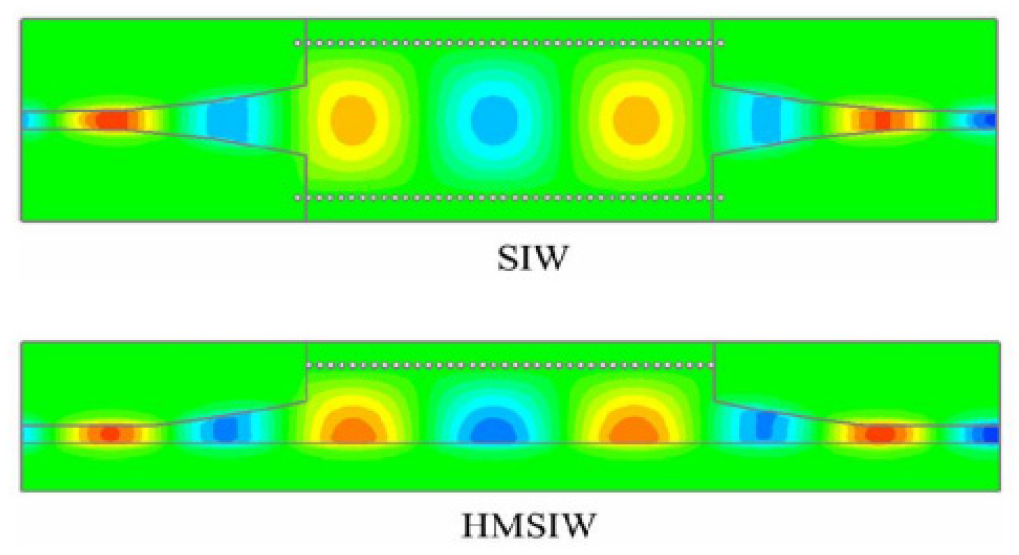
Half mode substrate integrated waveguide (HMSIW) [17] is primarily made by cutting the SIW structure from the centre. A small width is supplemented to account for the fringing field, as shown in Figure 3. For the dominant mode, if the plane along the transmission path is correspondent to the magnetic wall, the field distribution in half of the SIW will remain undisturbed.
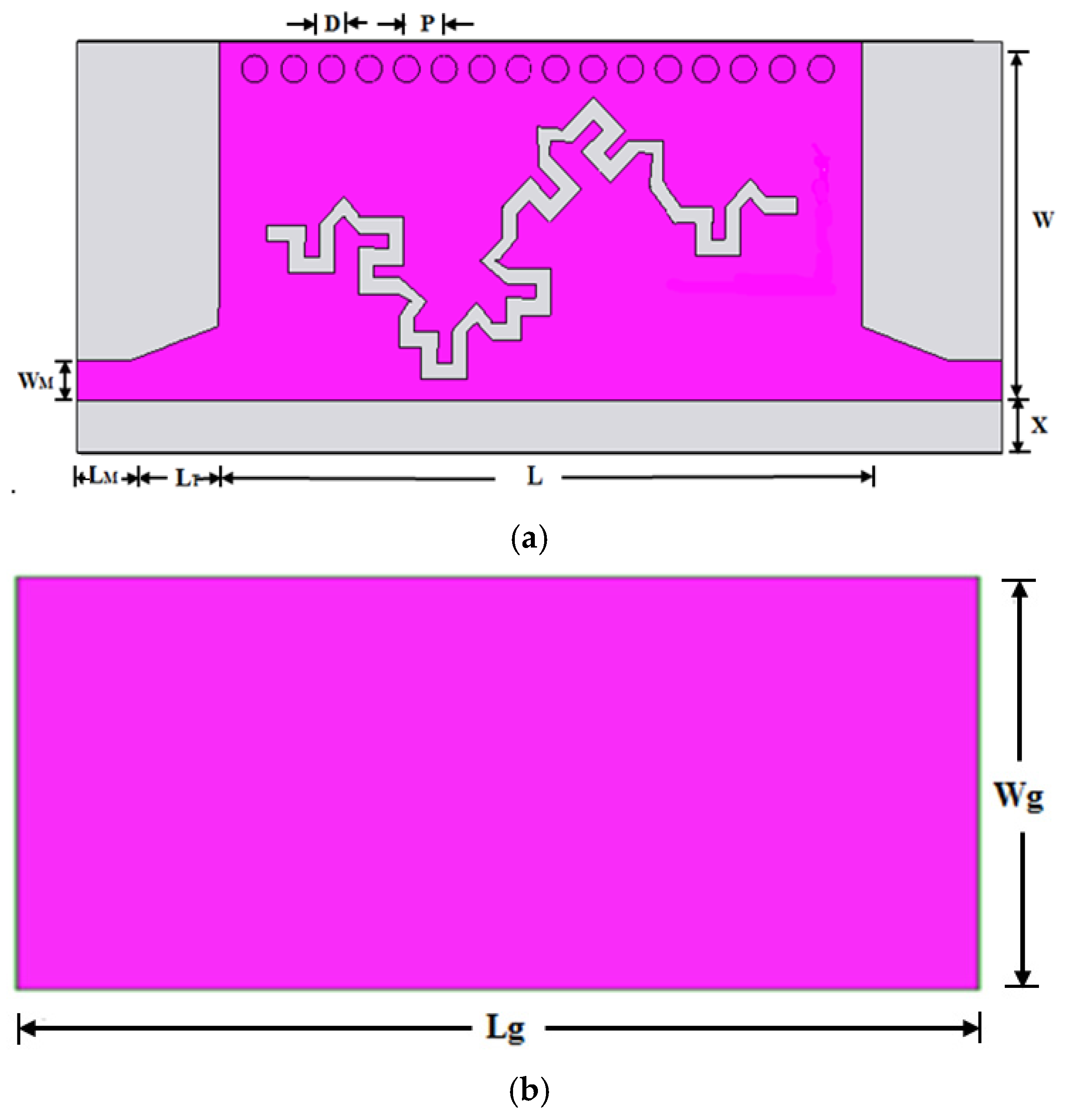
Figure 4a,b show the top and bottom view of the HFSS ver.13 simulated HMSIW structure integrated with the proposed hybrid fractal. For the design [18], the various parameters are as follows: SIW Length, L =19.2 mm; Microstrip line length, LM = 1.45 mm; Taper length, LT = 2.85 mm; Width of microstrip line, WM = 1.2 mm; Width of HMSIW, W = 5.75 mm; Via diameter, D = 1.0 mm; Pitch, P = 1.2 mm, X = 1.5 mm; Total length, Lg = 27.8 mm, and width, Wg = 7.25 mm.
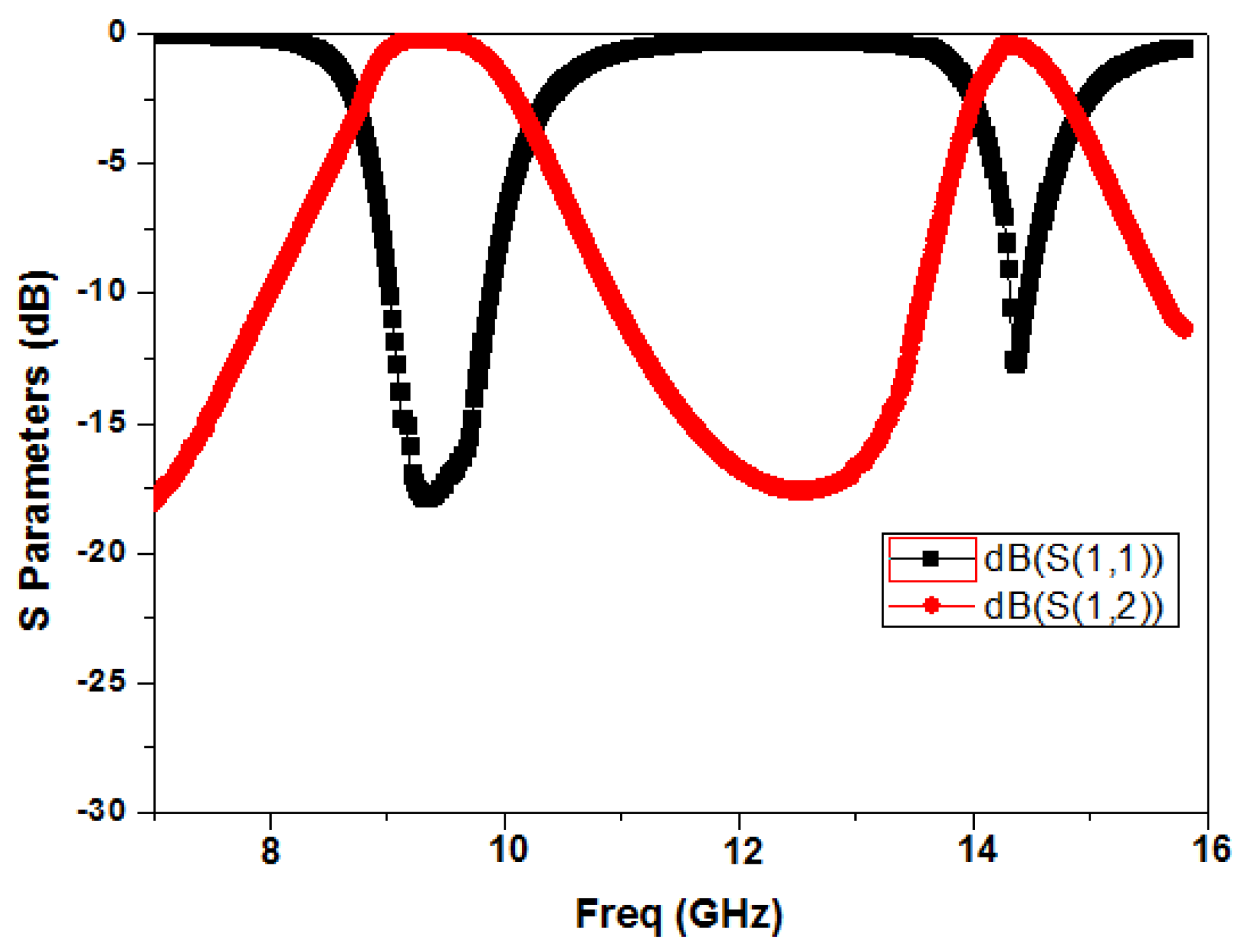
Figure 5 depicts the frequency response of multiband design with resonant frequency at 9.35 GHz and 14.4 GHz. As is evident from the response, it creates multiband with first passband having a centre frequency at 9.35 GHz and the bandwidth, Δf = 0.75, GHz is ranging from 9.05 GHz – 9.80 GHz.

4. Design of HMSIW BPF Integrated with CSRR Etched on the Bottom Plane

For the purpose of miniaturisation and improving the stop band response, a square-shaped CSRR unit as metamaterial is introduced at the centre of the bottom plane. The CSRR is predominately excited by the presence of an electric field. The CSRR can be correspondent to an electric dipole, resulting in a negative dielectric constant when it works in the vicinity of the resonant frequency.
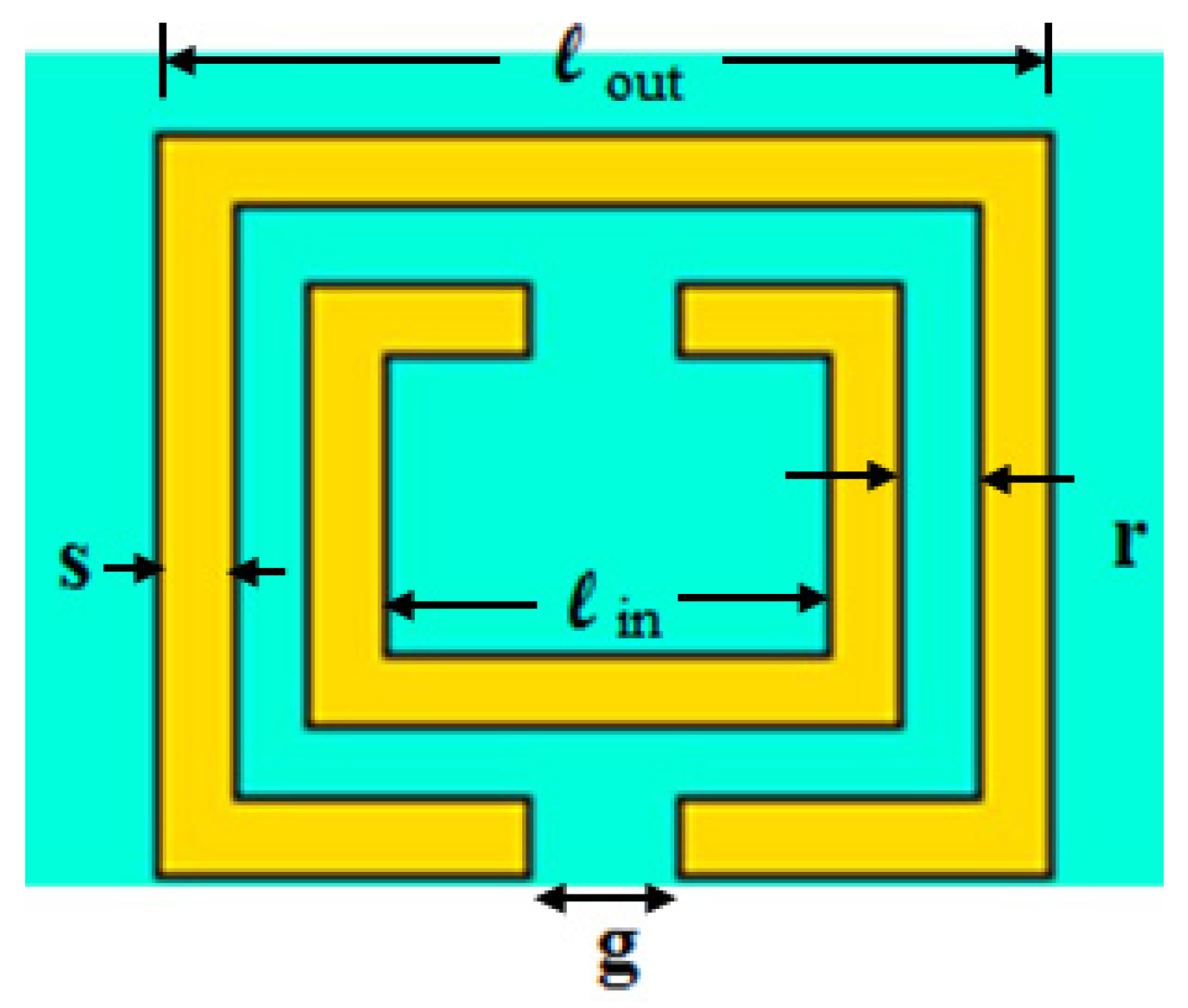
Figure 6 depicts the geometrical structure of the square CSRR unit cell. Its parameters are optimized to obtain the negative permittivity in the desired frequency range. The optimized parameters of the CSRR unit cell are: lout = 2.85 mm, lin = 2.2 mm, s = 0.25 mm, g = 0.40 mm, r = 0.3 mm.
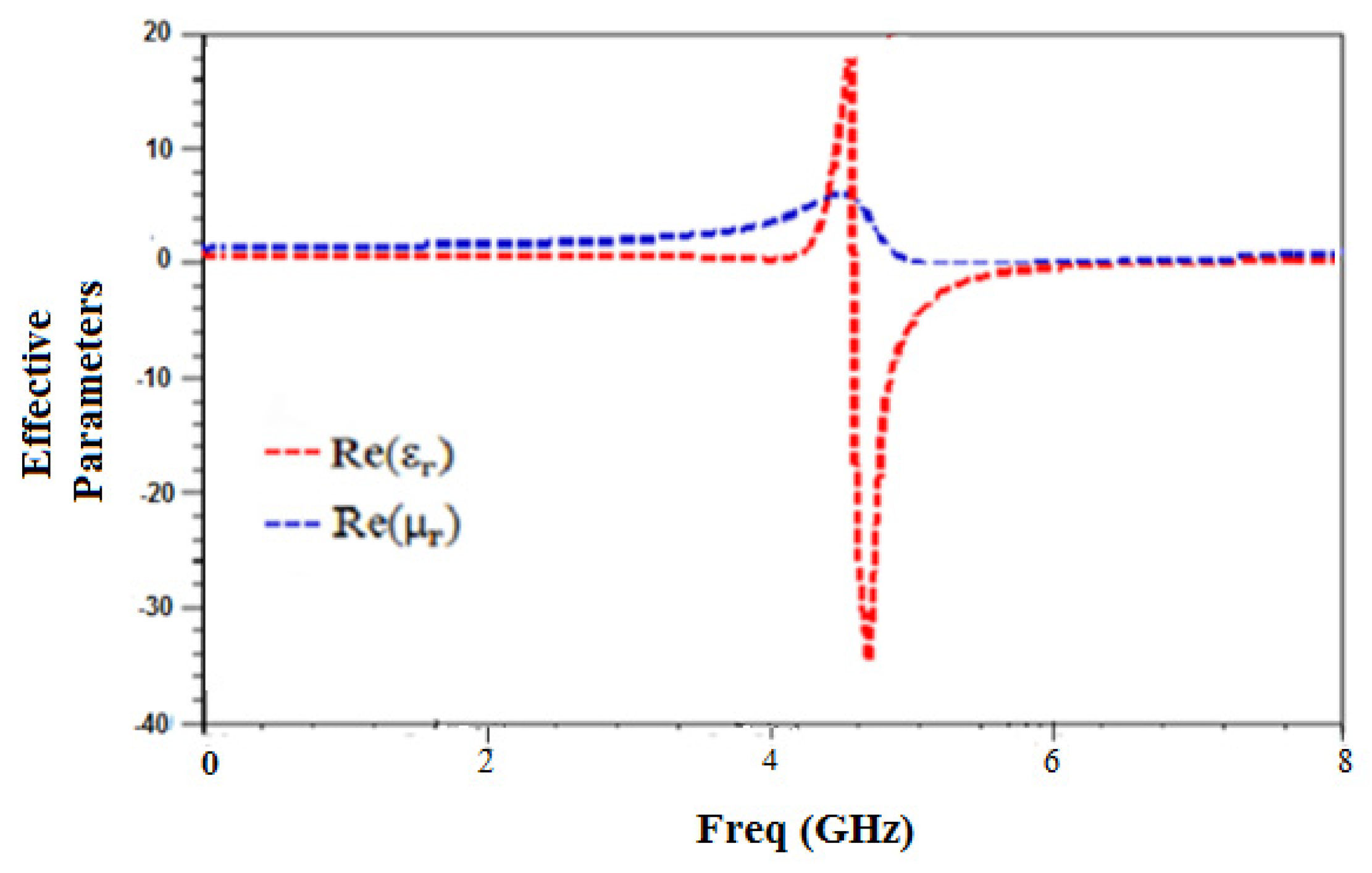
Figure 7 illustrates the effective parameters (εr and µr) of the CSRR. It is also evident from the graph that permittivity is negative from 4.30 GHz–5.85 GHz, validating the structure as an epsilon negative (ENG) type metamaterial. The method for parameter extraction to retrieve the material parameters (εr and µr) from the scattering parameters is elaborately presented in [19].
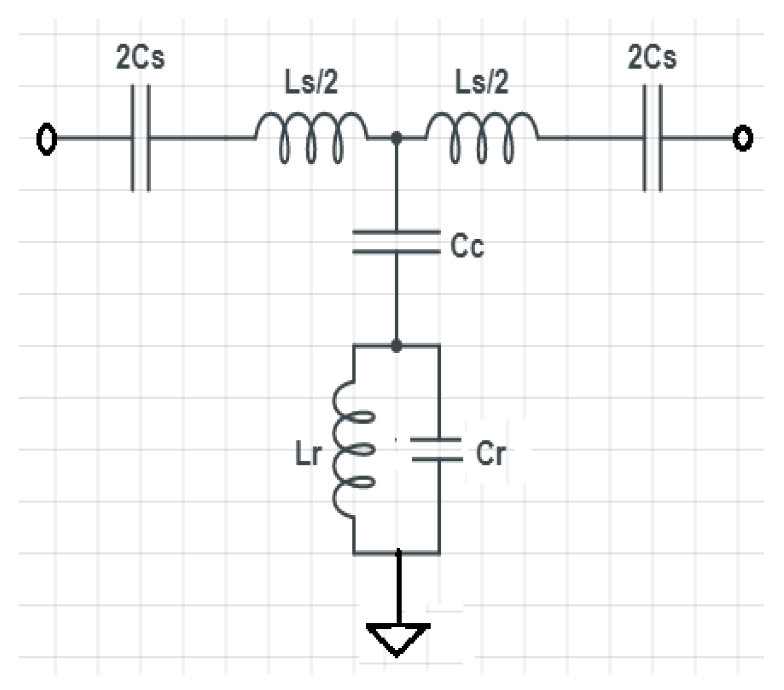
Figure 8 depicts the equivalent circuit of the half mode SIW incorporated with a CSRR cell. Here, Cr and Lr are the equivalent capacitance and inductance of the CSRR, respectively. Ls is the equivalent inductance of the metallic vias and Cs represents the slot capacitive reactance. Moreover, Cc represents the coupling capacitance amid the CSRR and the SIW transmission line.
In view of the equivalent circuit, the frequency of the TZ of the CSRR which nullifies the shunt impedance is given as [20]:
f z = 1 2 π L r ( C r + C c )    
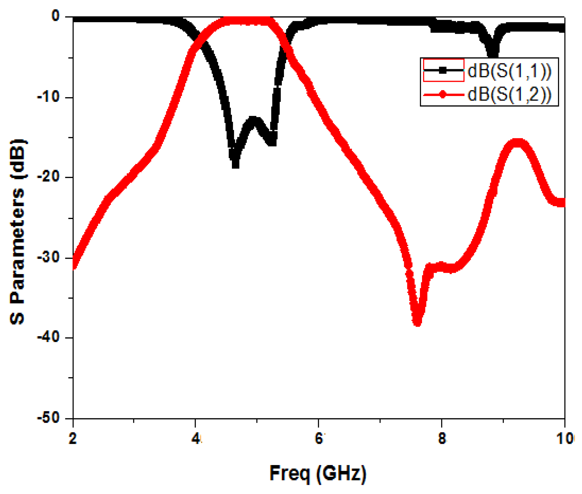
Figure 9 elucidates the frequency response of BPF after integrating a CSRR unit in the HMSIW structure. From Figure 9, it is evident that the two-pole filter has a pass band from 4.35 GHz to 5.4 GHz (with centre frequency fo = 4.85 GHz) and bandwidth of 1.05 GHz. Since CSRRs function as electric dipoles, they can be used in SIW to provide a pass band below the SIW cut-off frequency. As a result, CSRRs can be utilized to diminish the dimension of conventional SIW [21]. Further, there is a marginal improvement in bandwidth by the insertion of metamaterial [22]. In addition, it is evident that by introducing the CSRR, one transmission zero is achieved. As can be seen, a TZ is obtained adjacent to the upper passband edge at 7.45 GHz with an attenuation level of −39.5 dB, which slightly improves the skirt selectivity along with upper stop band performance [23]. The integration of the transmission line with the square CSRR with optimized dimensions resulted in preventing the propagation of electromagnetic waves, creating a TZ. The stop band is below −20 dB up to 1.80 f0 and the return loss is better than 13.8 dB, with an insertion loss of 0.62 dB. Further, two transmission poles in the pass band improve the filter’s pass band characteristics.

5. Design of Proposed Fractal HMSIW BPF Integrated with CSRR and Fractal DGS Etched on the Bottom Plane

After introducing the CSRR in a previous section, the stop band response is not adequately deep and wide, therefore, subsequently next step is to add a pair of Minkowski fractal DGS at each side of the CSRR to produce additional transmission zeros (TZs) which can further upsurge out-of-band rejection. The physical structure of the fractal DGS is shown in Figure 10. The optimized dimensions of various parameters are as follows: a = 0.65 mm, b = 1.0 mm, c = 0.20 mm, d = 4.15 mm.
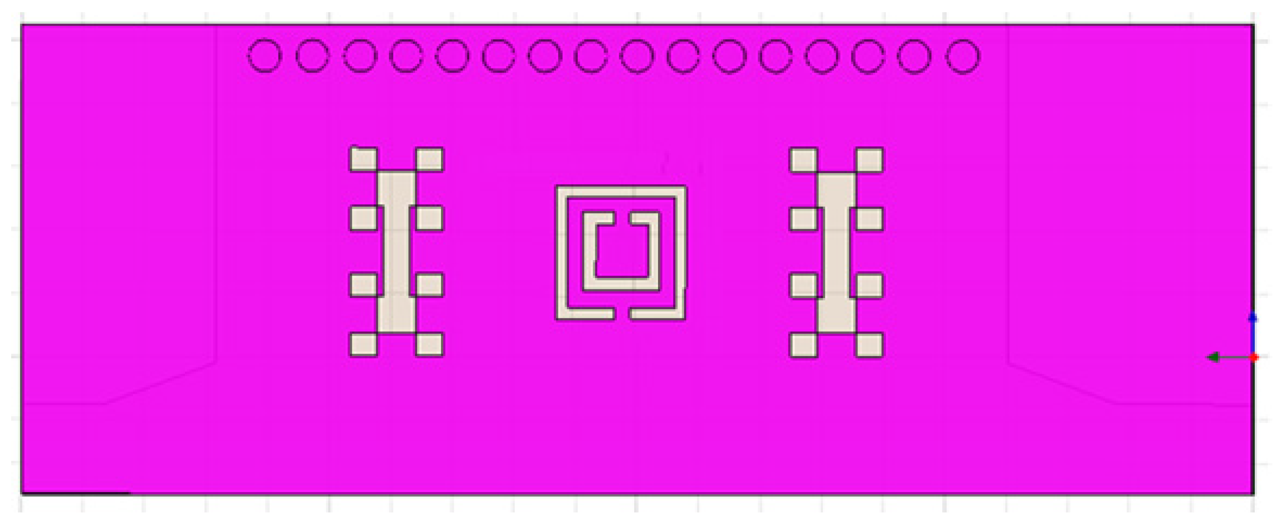
Figure 11 depicts the bottom view of the proposed filter with the fractal DGS on both sides of the CSRR which enhances the electromagnetic coupling [24]. The fractal DGS generates two additional transmission zeros (TZs) in the upper stop band due to coupling between the DGS pair and CSRR unit cell, which extraordinarily enhance the selectivity and stop band performance of the filter [25]. Moreover, any defect engraved in the ground plane alters the effective capacitance and inductance of the microstrip line, which also aids in suppressing higher mode harmonics and thereby widens the stop band [8].
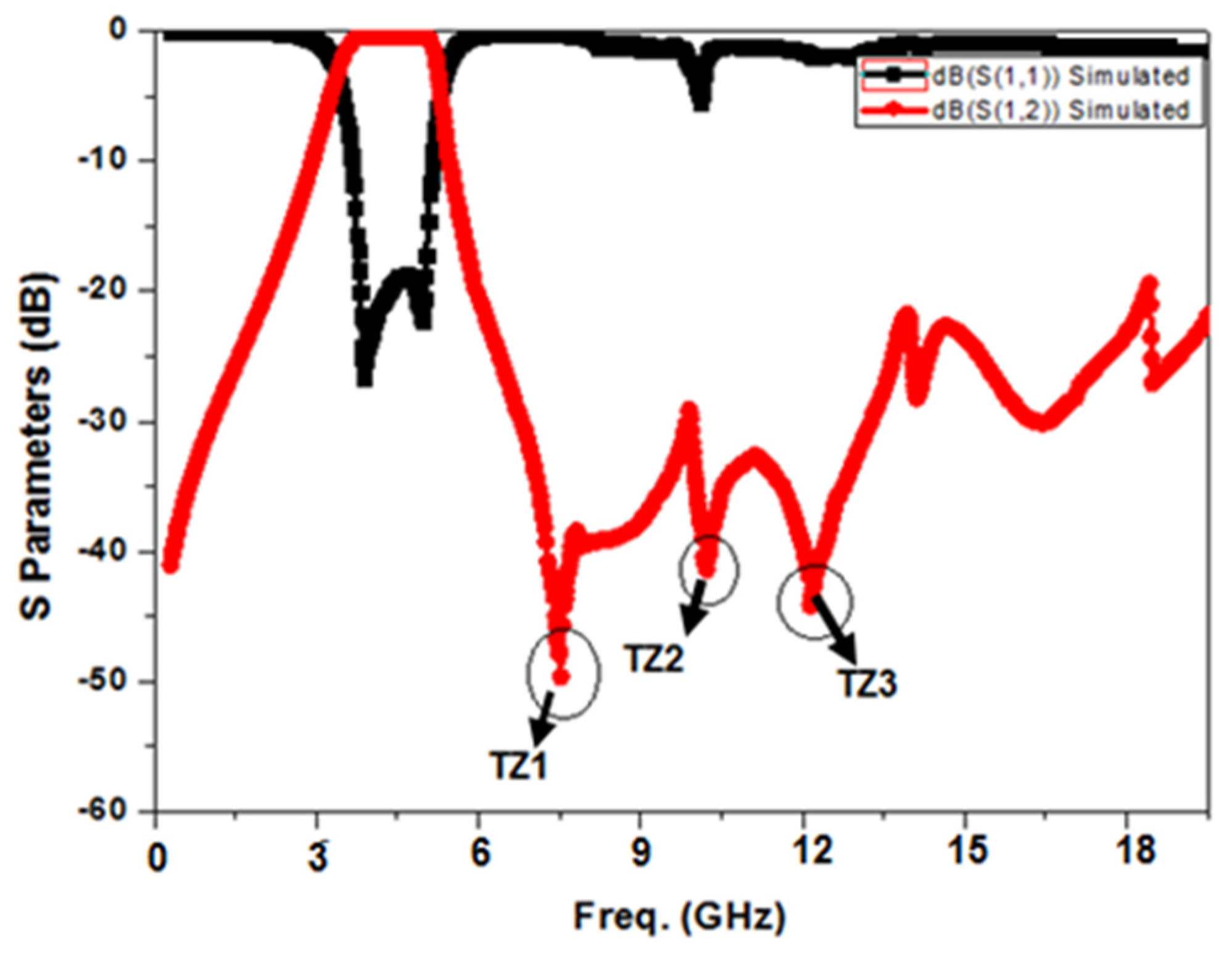
Figure 12 illustrates the HFSS simulated frequency response of the proposed BPF. It can be seen from the figure that the simulated pass band of the filter is from 3.65 GHz–5.17 GHz with bandwidth of 1.52 GHz. The return loss is better than 19.2 dB with an insertion loss of 0.85 dB. Further, three TZs are generated: one TZ (TZ1) due to the presence of a CSRR and two TZs (TZ2 and TZ3) by DGS coupling. The TZs are situated at 7.4 GHZ, 10.3 GHz and 12.15 GHz, with corresponding attenuation levels of −51.2 dB, −43 dB and −46.5 dB, respectively. These TZs enhance the pass band selectivity and broaden the stop band by greatly supressing the harmonic response [26].
Further, a slow-wave effect caused by the fact that the DGS line has elongated the electrical length aids in reducing the circuit size [27]. The simulation result shows that the proposed filter has an increased bandwidth of 1.52 GHz due to the addition of DGS. This increase of bandwidth can be explained by the fact that the ground plane’s defect augments the fringing field causing parasitic capacitance. This improved bandwidth is due to the higher coupling between the top and the ground plane, which results in improved bandwidth [28].

6. Fabrication and Result Discussion

To substantiate the result, the projected filter is designed with substrate FR4 with relative dielectric constant εr = 4.4 and having thickness 1.6 mm. Figure 13a,b portrays the snapshot of the upper and bottom layer of the fabricated filter with overall dimensions as: 27.80 mm (length) × 7.25 mm (width). A vector network analyser (VNA) model Anritsu S 820E has been used to measure the scattering parameters of the filter by the SOLT (short, open, load and thru) calibration method to nullify the losses of the cable.
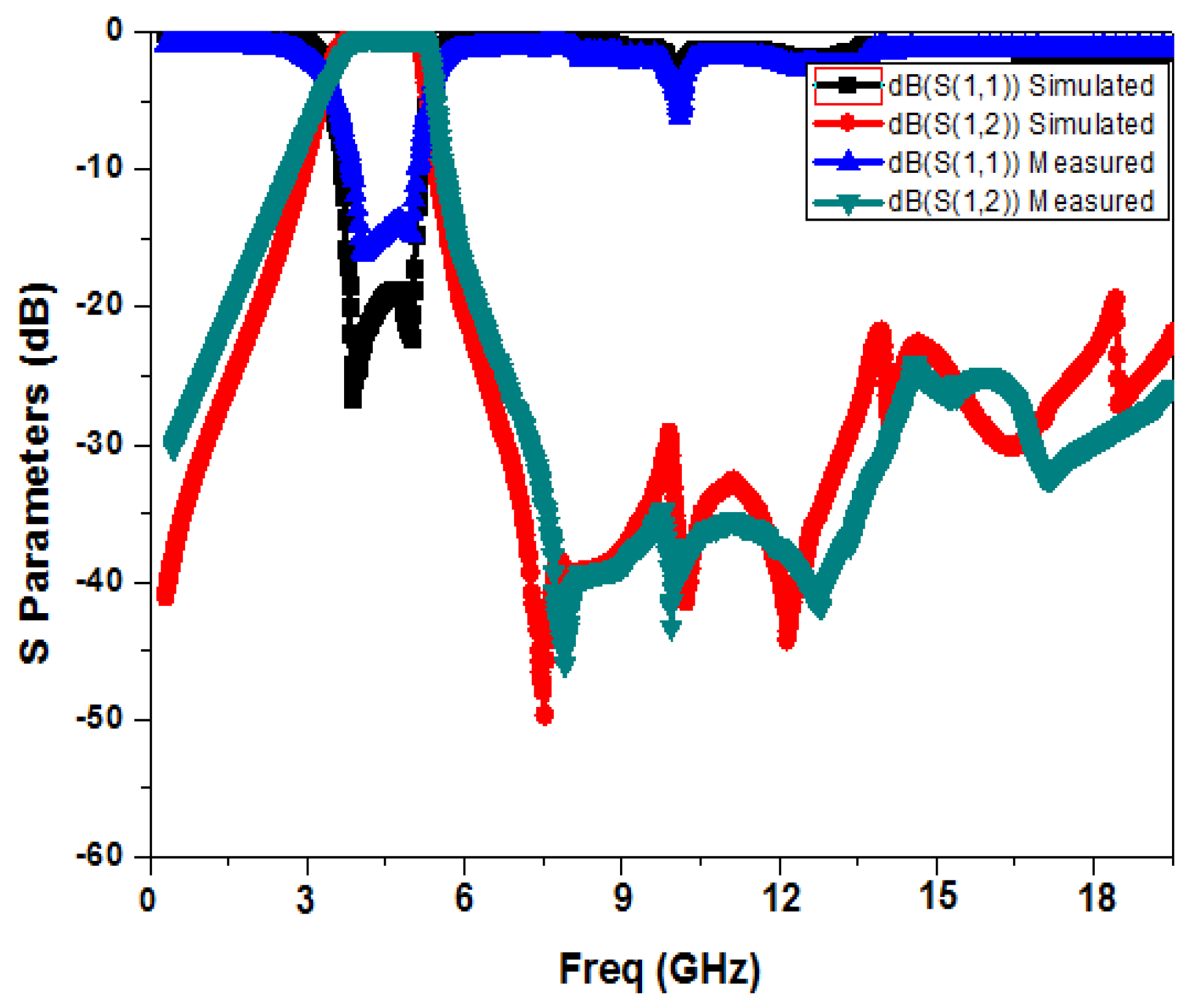
Figure 14 compares the measured and simulated results. It can be seen that the measurement results very much agree with the simulation results except for a slight discrepancy. This minor loss or discrepancy may be caused by the losses caused by SMA connectors and soldering. It can be seen from Figure 14 that the measured pass band of the filter is from 3.75 GHz–5.12 GHz with bandwidth of 1.38 GHz. The return loss is better than 14.8 dB with an insertion loss of 1.1 dB in the pass band. The TZs are situated at 7.65 GHZ, 9.97 GHz and 12.75 GHz, with corresponding attenuation levels of −46.8 dB, −42.4 dB and −41.2 dB, respectively. The average measured roll-off rate calculated is 72 dB/GHz with wide-stop band (attenuation > −20 dB above 20 GHz). The proposed fabricated filter has two poles located at 4.12 GHz and 5.05 GHz in the pass band.
To analyse the performance of the proposed filter, comparisons with some SIW filters for sub-6 GHz 5G applications are summarized in Table 1.
The design and performance of filters mentioned in comparison in Table 1 can be concisely summarized as follows: The filter proposed in [9] has a good return loss but the design is highly complex for fabrication. Moreover, the filter shows poor insertion loss and poor selectivity. The filter proposed in [10] has drawbacks of a large size and low roll-off rate due to the presence of only one TZ in the upper stop band. Although the filter proposed in [11] has a small size, its centre frequency (6.11 GHz) is very much towards the upper edge of the sub-6 GHz 5G spectrum; therefore, it has very limited applications. Moreover, its roll-off rate is moderate as it contains only one TZ in the upper stop band. The filter proposed in [12] was able to achieve better selectivity due to the TZs, but it has poor stop band performance due to a spurious harmonic response near the pass band. Moreover, the filter size is larger compared to our proposed filter. Finally, our proposed filter has a miniaturized size with an optimal insertion loss, high selectivity and good stop band performance due to the presence of three TZs in the upper stop band.

7. Conclusions

In the current work, a unique fractal HMSIW band pass filter using a CSRR unit cell and a pair of fractal DGS is simulated, fabricated and then verified. Firstly, a CSRR unit cell is embedded for miniaturisation and considerable improvement in the stop band by introducing one TZ. To further enhance the selectivity and stop band performance, a pair of DGS is incorporated across the CSRR. The measured result demonstrates that the filter attains wide bandwidth of 1.38 GHz with high selectivity and better stop band response for 5G applications. Moreover, upper stop band performance is below −20 dB, even beyond 20 GHz, achieving super wide-stop band. It is small in size owing to the half mode configuration. It may therefore be easily incorporated with a planar circuit for improved 5G communication services due to its voluminous advantages.

Author Contributions

Conceptualization, R.Z.V.; Software, A.C.; Validation, S.S.; Formal analysis, N.M.; Writing—original draft, N.M.; Supervision, M.E. and S.S.; Project administration, M.E. All authors have read and agreed to the published version of the manuscript.

Funding

This research received no external funding.

Institutional Review Board Statement

Not applicable.

Informed Consent Statement

Not applicable.

Data Availability Statement

Study did not report any data.

Acknowledgments

This work was undertaken during the tenure of an “ERCIM (The European Research Consortium for Informatics and Mathematics) Alain Bensoussan Fellowship” programme. Founded in 1988, ERCIM has members from leading European information technology and mathematics research establishments from 18 countries, with its head office in France.

Conflicts of Interest

The authors declare no conflict of interest.

References

  1. Gomez-Barquero, D.; Li, W.; Fuentes, M.; Xiong, J.; Araniti, G.; Akamine, C.; Wang, J. 5G for Broadband Multimedia Systems and Broadcasting. IEEE Trans. Broadcast. 2019, 65, 351–355. [Google Scholar] [CrossRef]
  2. Erunkulu, O.O.; Zungeru, A.M.; Lebekwe, C.K.; Mosalaosi, M.; Chuma, J.M. 5G Mobile Communication Applications: A Survey and Comparison of Use Cases. IEEE Access 2021, 9, 97251–97295. [Google Scholar] [CrossRef]
  3. Bozzi, M.; Georgiadis, A.; Wu, K. Review of substrate-integrated waveguide circuits and antennas. IET Microw. Antennas Propag. 2011, 5, 909–920. [Google Scholar] [CrossRef]
  4. Muchhal, N.; Srivastava, S. Review of recent trends on miniaturization of substrate integrated waveguide (SIW) components. In Proceedings of the 2017 3rd IEEE International Conference on Computational Intelligence & Communication Technology (CICT), Ghaziabad, India, 9–10 February 2017; pp. 1–6. [Google Scholar]
  5. Muchhal, N.; Srivastava, S. Design of miniaturized high selectivity folded substrate integrated waveguide band pass filter with Koch fractal. Electromagnetics 2019, 39, 571–581. [Google Scholar] [CrossRef]
  6. Muchhal, N.; Chakraborty, A.; Vishwakarma, M.; Srivastava, S. Slotted Folded Substrate Integrated Waveguide Band Pass Filter with Enhanced Bandwidth for Ku/K Band Applications. Prog. Electromagn. Res. 2018, 70, 51–60. [Google Scholar] [CrossRef]
  7. Muchhal, N.; Srivastava, S. Compact selective substrate integrated waveguide bandpass filter with S-shaped broadside-coupled complementary split ring resonators (BC-CSRR). Int. J. Microw. Opt. Technol. 2020, 15, 440–448. [Google Scholar]
  8. Muchhal, N.; Srivastava, S. Design of Compact and Wideband Comb shape SIW Multimode Resonator Band Pass filter. Int. J. RF Microw. Comput.-Aided Eng. 2019, 29, e21807. [Google Scholar] [CrossRef]
  9. Yang, T.; Chi, P.; Xu, R.; Lin, W. Folded Substrate Integrated Waveguide Based Composite Right/Left-Handed Transmission Line and Its Application to Partial $H$-Plane Filters. IEEE Trans. Microw. Theory Tech. 2013, 61, 789–799. [Google Scholar] [CrossRef]
  10. Wong, S.W.; Chen, R.S.; Lin, J.Y.; Zhu, L.; Chu, Q.X. Substrate Integrated Waveguide Quasi-Elliptic Filter Using Slot-Coupled and Microstrip-Line Cross-Coupled Structures. IEEE Trans. Compon. Packag. Manuf. Technol. 2016, 6, 1881–1888. [Google Scholar] [CrossRef]
  11. Duraisamy, T.; Barik, R.; Qingsha, S.C.; Selvajyothi, K.; Karthikeyan, S.S. Miniaturized SIW filter using D-shaped resonators with wide out-of-band rejection for 5G applications. J. Electromagn. Waves Appl. 2020, 34, 2397–2409. [Google Scholar] [CrossRef]
  12. Iqbal, A.; Jiat Tiang, J.; Kin Wong, S.; Alibakhshikenari, M.; Falcone, F.; Limiti, E. Multimode HMSIW-Based Bandpass Filter with Improved Selectivity for Fifth-Generation (5G) RF Front-Ends. Sensors 2020, 20, 7320. [Google Scholar] [CrossRef]
  13. Mandelbort, B.B. The Fractal Geometry of Nature; W.H. Freeman and Company: San Francisco, CA, USA, 1983. [Google Scholar]
  14. Tripathi, S.; Mohan, A.; Yadav, S. Ultra-wideband antenna using Minkowski-like fractal geometry. Microw. Opt. Technol. Lett. 2014, 56, 2273–2279. [Google Scholar] [CrossRef]
  15. Sharma, N.; Bhatia, S.S. Comparative analysis of hybrid fractal antennas: A Review. Int. J. RF Microw. Comput.-Aided Eng. 2021, 31, e22762. [Google Scholar] [CrossRef]
  16. Debnath, L. A brief historical introduction to fractals and fractal geometry. Int. J. Math. Educ. Sci. Technol. 2006, 37, 29–50. [Google Scholar] [CrossRef]
  17. Hong, W.; Liu, B.; Wang, Y.Q. Half Mode Substrate Integrated Waveguide: A New Guided Wave Structure for Microwave and Millimeter Wave Application. In Proceedings of the 2006 Joint 31st International Conference on Infrared Millimeter Waves and 14th International Conference on Teraherz Electronics, Shanghai, China, 18–22 September 2006; p. 219. [Google Scholar]
  18. Zamzam, K.; Bornemann, J. Designing the width of substrate integrated waveguide structures. IEEE Microw. Wirel. Compon. Lett. 2003, 23, 518–522. [Google Scholar]
  19. Muchhal, N.; Srivastava, S.; Elkhouly, M. Analysis and Design of Miniaturized Substrate Integrated Waveguide CSRR Bandpass Filters for Wireless Communication. In Recent Microwave Technologies; IntechOpen: London, UK, 2022. [Google Scholar] [CrossRef]
  20. Jiang, W.; Shen, W.; Zhou, L.; Yin, W.-Y. Miniaturized and high-selectivity substrate integrated waveguide (SIW) bandpass filter loaded by complementary split-ring resonators (CSRRs). J. Electromagn. Waves Appl. 2012, 26, 1448–1459. [Google Scholar] [CrossRef]
  21. Dong, Y.D.; Yang, T.; Itoh, T. Substrate Integrated Waveguide Loaded by Complementary Split-Ring Resonators and Its Applications to Miniaturized Waveguide Filters. IEEE Trans. Microw. Theory Tech. 2009, 57, 2211–2223. [Google Scholar] [CrossRef]
  22. Yoonjae, L.; Tse, S.; Yang, H.; Parini, C.G. A compact microstrip antenna with improved bandwidth using complementary split-ring resonator (CSRR) loading. In Proceedings of the 2007 IEEE Antennas and Propagation Society International Symposium, Honolulu, HI, USA, 9–15 June 2007; pp. 5431–5434. [Google Scholar]
  23. Zhang, J.; Cui, B.; Lin, S.; Sun, X.W. Sharp-Rejection Low-Pass Filter with Controllable Transmission Zero using Complementary Split Ring Resonators (CSRRs). Prog. Electromagn. Res. PIER 2007, 69, 219–226. [Google Scholar] [CrossRef] [Green Version]
  24. Weiping, L.; Zongxi, T.; Xin, C. Design of a SIW Bandpass Filter Using Defected Ground Structure with CSRRs. Hindawi Act. Passiv. Electron. Compon. 2017, 2017, 1606341. [Google Scholar]
  25. Ali, A.R.; Abdel, R.S.; Omar, A.S. Direct and cross-coupled resonator filters using defected ground structure (DGS) resonators. In Proceedings of the 2005 European Microwave Conference, Paris, France, 4–6 October 2005; pp. 1275–1278. [Google Scholar]
  26. Hadarig, R.C.; De Cos, G.; Las-Heras, F. A Compact Band-Pass Filter with High Selectivity and Second Harmonic Suppression. Materials 2013, 6, 5613–5624. [Google Scholar] [CrossRef] [Green Version]
  27. Arya, A.K.; Kartikeyan, M.V.; Patnaik, A. Defected Ground Structure in the perspective of Microstrip Antennas: A Review. Frequenz 2010, 64, 79–84. [Google Scholar] [CrossRef]
  28. Zhang, Y.L.; Hong, W.; Wu, K.; Chen, J.X.; Tang, H.J. Novel substrate integrated waveguide cavity filter with defected ground structure. IEEE Trans. Microw. Theory Tech. 2005, 53, 1280–1286. [Google Scholar] [CrossRef]
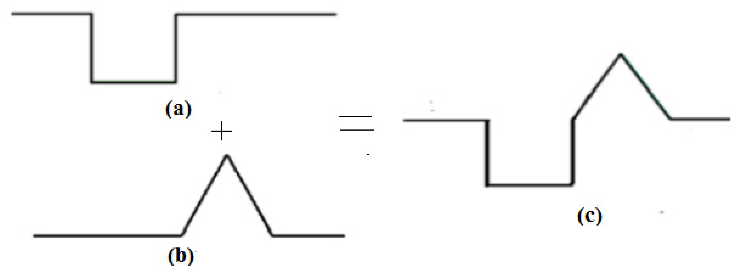
Figure 1. (a) Minkowski curve fractal, (b) Koch curve fractal and (c) hybrid fractal structure.
Photonics 09 00898 g001
Figure 2. Proposed geometry of fractal after second iteration (n = 2).
Photonics 09 00898 g002
Figure 3. Field distribution in SIW and HMSIW [17].
Photonics 09 00898 g003
Figure 4. (a) Top view of HMSIW integrated with hybrid fractal. (b) Back view of HMSIW integrated with hybrid fractal.
Photonics 09 00898 g004
Figure 5. Frequency response of HMSIW integrated with hybrid fractal.
Photonics 09 00898 g005
Figure 6. Square-ring CSRR unit cell.
Photonics 09 00898 g006
Figure 7. Extracted parameters of the metamaterial unit cell.
Photonics 09 00898 g007
Figure 8. Equivalent circuit of HMSIW BPF with CSRR.
Photonics 09 00898 g008
Figure 9. Frequency response of HMSIW BPF with CSRR unit cell.
Photonics 09 00898 g009
Figure 10. Fractal DGS.
Photonics 09 00898 g010
Figure 11. Bottom view of the proposed BPF with DGS and CSRR.
Photonics 09 00898 g011
Figure 12. Simulated frequency response of the proposed BPF.
Photonics 09 00898 g012
Figure 13. (a) Top and (b) bottom views of fabricated band pass filter.
Photonics 09 00898 g013
Figure 14. Comparison of simulated and measured results.
Photonics 09 00898 g014
Table 1. Evaluation of performance with recently reported SIW BPFs for sub-6GHz 5G application.
Referencefo
(GHz)
RL/IL *Technique UsedAvg. Roll-off Rate #
(dB/GHz)
3-dB FBW (%)Out-of-Band Rejection
(>−20 dB)
mm × mm
0 × λ0)
[9]5.320/1.8FSIW technique466.20.68 fo29.6 × 7.6
(0.62 λ0 × 0.26 λ0)
[10]3.718/1.1Slot and cross-coupling technique57.514.2N.A.120 × 30
(1.47 λ0 × 0.37 λ0)
[11]6.1119/1.2CSRR52.58.93.28 fo25 × 9.5 = 237.5
(0.52 λ0 × 0.19 λ0)
[12]4.6715/1Multimode HMSIW64.569.30.65 fo43.5 × 29.5
(0.69 λ0 × 0.46 λ0)
Proposed5.214.5/1.1HMSIW with DGS and CSRR7226.34.1 fo27.8 × 7.25
(0.55 λ0 × 0.21 λ0)
# Roll-off rate is based on the computation from the techniques’ respective scattering (S) parameter graphs. * RL: Return loss, IL: Insertion loss.
Publisher’s Note: MDPI stays neutral with regard to jurisdictional claims in published maps and institutional affiliations.