Abstract
We propose a compact, high extinction ratio, and low-loss polarization beam splitter (PBS) on a lithium-niobate-on-insulator (LNOI) platform, based on an asymmetrical directional coupler and using a silicon nitride nanowire assisted waveguide (WG) and a grooved WG. By properly designing nanowires and grooved LN WGs, TE polarization meets the phase matching condition, while significant mismatching exists for TM polarization. Numerical simulations show that the PBS has an ultra-high extinction ratio (ER) of and (larger than 40 dB and 50 dB, respectively). The device extinction ratios are larger than 10 dB over 100 nm wavelength ranges. Moreover, the device has an ultra-low insertion loss (IL less than 0.05 dB) at the wavelength of 1550 nm and maintains ILs less than 0.4 dB over 100 nm wavelength ranges.
1. Introduction
Lithium niobate (LN) is known as an excellent optical material in the field of communication technology because of its excellent performance in electro-optic, acousto-optic, and nonlinear optics. Due to the low refractive index difference between the core and cladding (n < 0.02), the traditional ion diffusion ln waveguides (WGs) have weak restrictions on the optical field and are difficult to reduce the device size. Thanks to the progress of thin film lithium-niobate (LN) manufacturing technology [1], lithium niobate on insulator (LNOI) can achieve sub-wavelength light limitation, which has broad application prospects for photonic integrated circuits (PIC) [2]. Similar to the other high-index-contrast platforms, LNOI suffers from the polarization-dependent problem due to the birefringence caused by the asymmetrical waveguide structures and the inherent anisotropy property of LN [3]. Therefore, polarization diversity systems are needed to solve these problems in PICs.
Recently, adiabatic coupler [4], Mach Zehnder interferometer [5,6], and subwavelength grating [7] have been used to realize wideband PBS on LNOI platform. However, these PBSs have a large footprint and limited application.
Asymmetric directional coupler (ADC) has been proved to be a simple method to realize compact PBS on other platforms, such as silicon on insulator (SOI) [8]. It is well known that the refractive index difference between fundamental transverse electric mode () and fundamental transverse magnetic mode () of quasi-single mode silicon WG with a typical thickness of 220 nm is about 0.7. With high birefringence, compact PBS based on the on-chip ADC can be achieved on SOI by using different widths WGs [9,10,11]. However, LNOI waveguide birefringence is much smaller than SOI [12,13,14]. For example, the refractive index difference between and of LN single-mode waveguide with a height of 400 nm is usually less than 0.2. Therefore, this kind of design may not be suitable for LNOI.
Hybrid plasmonic waveguide (HPW) [15,16] is another effective way to enhance birefringence to realize compact PBS [17,18,19]. Depositing metal on the waveguide can change the refractive index of TM polarization. This design significantly enhances the birefringence of the waveguide, to split TE and TM mode. However, due to the inherent metallic absorption, the insertion loss of HPW is high.
In this paper, we propose a PBS consisted of a silicon nitride nanowire assisted waveguide and a grooved waveguide, which realizes compact, high extinction ratio, and low loss on LNOI platform. Table 1 lists the comparison between LNOI-based PBSs proposed recently and work in this paper. Our device is very competitive, especially in the x-cut platform. Most importantly, we can finely adjust the refractive index of TE mode to achieve a high extinction ratio (>40 dB) of TE mode. Moreover, with the help of silicon nitride nanowires, the refractive index of TM polarization increases significantly, while the refractive index of TM polarization in the grooved waveguide is low [20]. Therefore, when TE polarization meets the phase matching condition, the TM polarization coupling mismatch is large to achieve a high extinction ratio (>50 dB) of TM mode. The results show that the compact PBS based on silicon nitride nanowire assisted waveguide and grooved waveguide has excellent performance on LNOI platform. And this PBS can tolerate large manufacturing errors.

Table 1.
Comparison of PBSs based on the LNOI platform.
2. Materials and Methods
Figure 1a,b respectively present schematics of the top and cross-sectional views of the proposed PBS. The device consists of two WGs (WG1, WG2) with coupling gap G. WG1 is a nanowire assisted waveguide and it ends with a through-output port. WG2 is a grooved-waveguide ending with a cross output port. The S-shaped curved waveguide with length is used to decouple WG1 and WG2. The thickness of LN layer is 500 nm and embedded layer (box) is 2 μm. The waveguide height is 300 nm, and is covered on the upper layer to protect WGs. The refractive indices of LN, and are = 2.21, = 2.46 (which is relatively larger as the fabrication of film deposition is PEVED) and = 1.44 at the wavelength of 1550 nm, respectively.

Figure 1.
Schematics of proposed PBS; (a) top view and (b) cross-section view.
Although the Z-cut platform is more advantageous to design PBS, the existing LNOI electro-optic modulators are generally manufactured based on the X-cut platform to take advantage of the high electro-optic coefficient of the Z-axis. Considering that PBS will be integrated with modulators in the future, our design is based on X-cut LNOI platform [21]. LN WGs can be patterned with high resolution using Electron Beam Lithography (EBL) and Inductively Coupled Plasma Reactive Ion Etching (ICP-RIE). Limited by the manufacturing process, the side wall of LN WG manufactured by ICP-RIE inclines about 75° [22]. Therefore, we set the sidewall corner (θ) at 75° to match the manufacturing process.
By optimizing the geometric parameters (, ) of nanowires, the effective refractive index (Neff) of mode can be significantly improved, while the Neff of mode can be slightly improved. Then, by optimizing the parameters (, , ) of grooved LN WG, the TE polarization can meet the phase matching condition, and there is a large phase mismatch of TM polarization, to significantly inhibit the cross-coupling of TM polarization. In this case, TE and TM can be separated after going through a short coupling region.
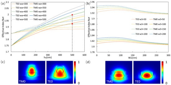
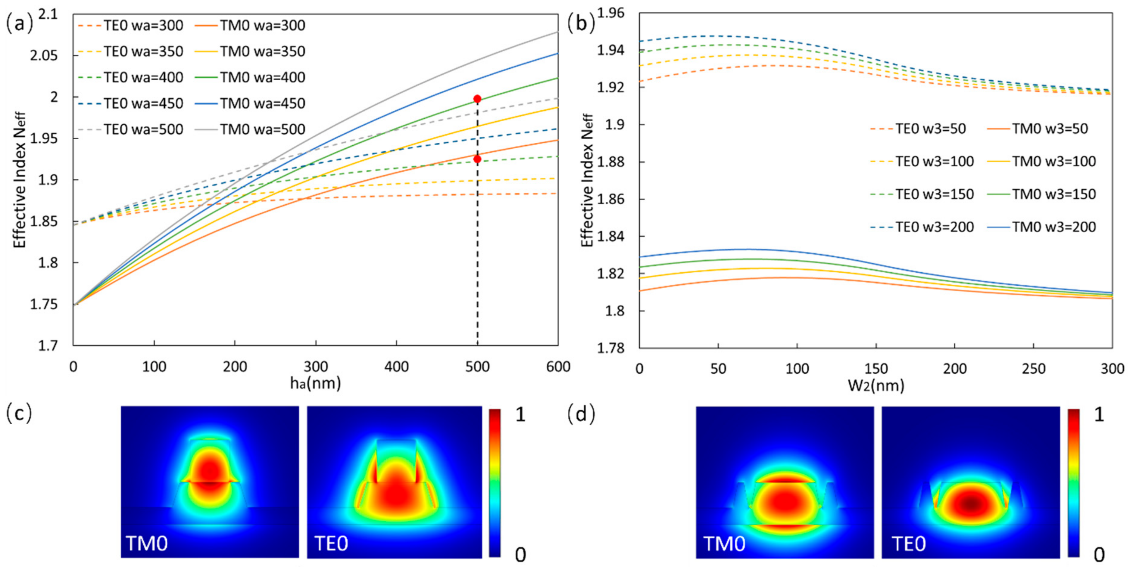
When the nanowires are loaded on LN WGs, the electric fields of TE polarization (whose main electrical field is horizontal) and TM polarization (whose main electrical field is vertical) will be affected differently. Figure 2a shows the Neff of and in assisted LNWG at the wavelength of 1.55 μm. We use Lumerical Finite Difference Eigenmode (FDE) solver to calculate their Neff. In the calculation, is fixed at 600 nm. It can be seen that for both polarizations, Neff increases with and . However, with the increase of , Neff of will approach and exceed Neff of eventually. According to Figure 2b, we choose (, ) = (400, 500) nm, to match the Neff of of grooved WG (~1.93), and to significantly increase Neff of . Figure 2c shows the relevant electric field distribution of and modes in the case of (, ) = (400, 500) nm.

Figure 2.
(a) Calculated effective indices of and modes in assisted LN WGs as a function of ha for different . (b) Calculated effective indices of and modes in grooved LN WGs as a function of for different . (c) Electrical field profiles for mode (, ) = (400, 500) nm, mode (, ) = (400, 500) nm. (d) Electrical field profiles for mode (, ) = (200, 100) nm, mode (, ) = (200, 100) nm.
When the LN WGs are grooved, and will also be affected differently. Figure 3a shows the Neff of and modes in grooved LNWG at 1.55 μm wavelength. We also use the Lumerical FDE solver to calculate their Neff. In the calculation, is fixed at 1μm. And we assume that when is narrow, WG cannot be etched completely, but small pits are formed on the WG [23]. It can be seen that for both modes, Neff of grooved waveguide first increases and then decreases with the increase of , and gradually approaches Neff of single-mode WG with the width . So it is convenient for us to design Neff of TE polarization. According to Figure 3a, we select (, ) as (200, 100) nm to exact match Neff of mode. Figure 3b shows the electric field of and modes in the case of (, ) = (200, 100) nm.

Figure 3.
(a) Calculated effective index of and modes in Si3N4 assisted LN WGs and grooved LN WGs as a function of WG width. Electrical field profiles of (b) two quasi-TM super-modes, and of (c) odd and even TE super-modes in the coupling region.
Then, we calculate the Neff as a function of the width of WG at 1.55 μm wavelength, as shown in Figure 3 We choose as 1μm and as 600 nm. As expected, the meets the phase matching condition, while the Neff of is significantly different.
3. Results
Lumerical 3D finite-difference time-domain (FDTD) is applied to further simulate the light transmission characteristics of the proposed structure. Cross-coupling length of mode is determined by G. The smaller G is, the smaller coupling length of the DC is. However, undesired TM polarization cross-coupling will also increase due to the insufficient phase-mismatch caused by smaller G. Therefore, G is optimized to 1380 nm. is optimized to 393 nm to obtain the maximum ER of . Considering the complete coupling of mode, is optimized to 36 μm. And is set to 2 μm to avoid accidental coupling between two WGS. is set to 10μm to ensure a low bending loss.
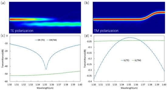
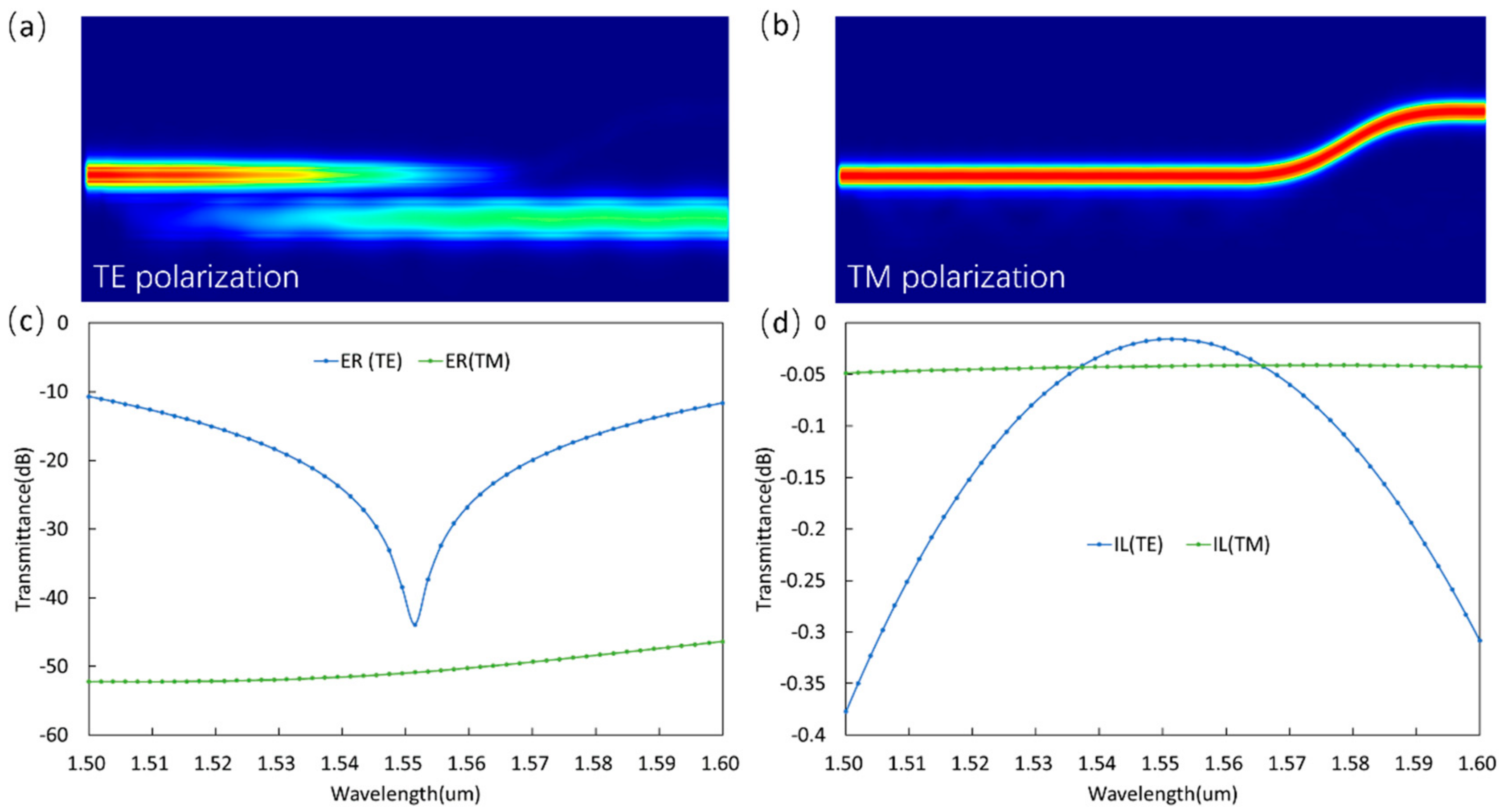
Figure 4a,b show the light propagation profiles of and at 1.55 μm, respectively. It can be seen that is completely coupled with the cross port, while has almost no coupling. The Extinction Ratio (ER) of is 40.7 dB (mainly propagates from the cross port), while is 50.7 dB (mainly propagates from the through port). For both polarizations, ultra-low Insertion Loss (IL < 0.05 dB) can be achieved. ER and IL are defined as follows:

Figure 4.
Light propagation profiles of (a) TE polarization and (b) TM polarization at the wavelength of 1550 nm; ER and IL of (c) TE polarization and (d) TM polarization as wavelength varies.
and are the through port and cross port transmission, respectively. Figure 4c,d show ERs and ILs of TE and TM polarization, respectively. It can be observed that for both polarizations, our PBS shows broadband performance with ERs > 10 dB over 100 nm wavelength ranges. In the wavelength range of 100 nm, the IL of TE polarization is less than 0.4 dB, and that of TM polarization is less than 0.05 dB The ILs of TM polarization is mainly caused by bending, which can be further reduced by increasing .
The manufacturing tolerance is considered of four parameters, that is, (1) Etching depth error of grooves on LN film δh, (because narrow grooves are difficult to etch), (2) the sidewall angle of WGs δθ, (3) width of WGs δw (assuming that the two WGS have the same change), (4) mask misalignment δm (mask misalignment will cause the horizontal position of nanowires to shift). And Figure 5 shows the transmission spectrum of the corresponding parameters deviating from the optimized value. For both polarizations, When the range of δh/δθ/δw/δm is 30 nm/±3°/±20 nm/±30 nm, ER > 10 dB and IL < 0.5 dB of and ER > 40 dB and IL < 0.05 dB of can still be maintained in the 160 nm bandwidth. It is worth noting that is much less sensitive to fabrication errors and wavelength changes than , which is caused by the large phase mismatch of .

Figure 5.
(a) Four parameters of manufacturing tolerance. (b) ERs and (c) ILs of the device with parameters deviating from the optimized value.
4. Discussion
In fact, single LN WG is easier to manufacture than grooved LN WG. We have tried to use single LN WG instead of grooved waveguide to build PBS as in reference [13]. However, there are few parameters that can be changed for a single LN WG. So it is difficult to design the Neff, resulting in poor extinction ratio. The groove waveguide we propose has three parameters that can be flexibly adjusted (w1, w2 and w3) to precisely design Neff of and . Therefore, replacing LN WG with groove waveguide can make Neff of TE match better and Neff of TM difference larger, thus improving extinction ratio.
5. Conclusions
In this paper, we propose a compact, high extinction ratio, and low loss PBS based on an asymmetric directional coupler on LNOI platform. nanowires are deposited on LN waveguides to significantly change birefringence. By properly designing nanowires and grooved LN WGS, TE polarization meets the phase matching condition. However, TM polarization has an obvious phase mismatch, and the coupling is fully suppressed. We design a PBS with a length of 46 μm (including S-bend). Simulations show that the PBS has an ultra-high extinction ratio (ER) of and (larger than 40 dB and 50 dB, respectively). Simulation shows that PBS has the broadband performance of keeping ERs > 10 dB in the 100 nm wavelength range. In addition, PBS shows ultra-low IL (<0.05 dB) and maintains ILs < 0.4 dB in the 100 nm wavelength range. This device has good manufacturing error tolerance. We believe that our work paves the way for the integrated polarization control system on the LNOI platform.
Author Contributions
Conceptualization, J.T. and X.L.; methodology, J.T. and S.D.; software, J.T. and X.L.; validation, J.T. and X.L.; formal analysis, Y.Z. and C.W.; writing—original draft preparation, J.T.; writing—review and editing, J.L. (Jinye Li) and Y.Z.; project administration, J.L. (Jianguo Liu). X.L. and J.L. (Jinye Li) has made equal contributions to this work. All authors have read and agreed to the published version of the manuscript.
Funding
This research was funded by National Natural Science Foundation of China (NSFC), grant number 61727815, and 61731014.
Conflicts of Interest
The authors declare no conflict of interest.
References
- Wang, C.; Zhang, M.; Chen, X.; Bertrand, M.; Shams-Ansari, A.; Chandrasekhar, S.; Winzer, P.; Loncar, M. Integrated lithium niobate electro-optic modulators operating at CMOS-compatible voltages. Nature 2018, 562, 101–104. [Google Scholar] [CrossRef] [PubMed]
- Zhang, Y.; Wang, X.; Li, Z.; Lyu, W.; Lyu, Y.; Zeng, C.; Zhang, Z.; Zhang, S.; Zhang, Y.; Li, H.; et al. Flat Optical Frequency Comb Generation Based on Monolithic Integrated LNOI Intensity and Phase Modulator. Photonics 2022, 9, 495. [Google Scholar] [CrossRef]
- Wang, J.; Chen, P.; Dai, D.; Liu, L. Polarization coupling of x-cut thin film lithium niobate based waveguides. IEEE Photon. J. 2020, 12, 2200310. [Google Scholar] [CrossRef]
- Yang, G.; Sergienko, A.; Ndao, A. Plasmonic loss-mitigating broadband adiabatic polarizing beam splitter. Opt. Lett. 2022, 47, 629–632. [Google Scholar] [CrossRef]
- Chung, H.; Lee, C.; Huang, K.; Yang, S.; Wang, K.; Solntsev, A.; Sukhorukov, A.; Setzpfandt, F.; Chen, Y. Broadband on-chip polarization mode splitters in lithium niobate integrated adiabatic couplers. Opt. Express 2019, 27, 1632–1645. [Google Scholar] [CrossRef]
- Xu, H.; Dai, D.; Liu, L.; Shi, Y. Proposal for an ultra-broadband polarization beam splitter using an anisotropy-engineered Mach-Zehnder interferometer on the x-cut lithium-niobate-on-insulator. Opt. Express 2020, 28, 10899–10908. [Google Scholar] [CrossRef]
- Deng, C.; Lu, M.; Sun, Y.; Huang, L.; Wang, D.; Hu, G.; Zhang, R.; Yun, B.; Cui, Y. Broadband and compact polarization beam splitter in LNOI hetero-anisotropic metamaterials. Opt. Express 2021, 29, 11627–11634. [Google Scholar] [CrossRef]
- Dai, D. Advanced passive silicon photonic devices with asymmetric waveguide structures. Proc. IEEE 2018, 106, 2117–2143. [Google Scholar] [CrossRef]
- Fukuda, H.; Yamada, K.; Tsuchizawa, T.; Watanabe, T.; Shinojima, H.; Itabashi, S.I. Ultrasmall polarization splitter based on silicon wire waveguides. Opt. Express 2006, 14, 12401–12408. [Google Scholar] [CrossRef]
- Wu, H.; Tan, Y.; Dai, D. Ultra-broadband high-performance polarizing beam splitter on silicon. Opt. Express 2017, 25, 6069. [Google Scholar] [CrossRef]
- Dai, D.; Bowers, J.E. Novel ultra-short and ultra-broadband polarization beam splitter based on a bent directional coupler. Opt. Express 2011, 19, 18614–18620. [Google Scholar] [CrossRef]
- Jiang, R.; Xu, Y.; Dong, Y.; Zhang, B.; Ni, Y. Integrated TM-through/TE-converted polarization beam splitter based on z-cut lithium niobate-on-insulator platform. Optik 2022, 255, 168690. [Google Scholar] [CrossRef]
- Zhang, L.; Zhang, L.; Fu, X.; Yang, L. Compact, Broadband and Low-Loss Polarization Beam Splitter on Lithium-Niobate-On-Insulator Using a Silicon Nanowire Assisted Waveguide. IEEE Photon. J. 2020, 12, 6601906. [Google Scholar] [CrossRef]
- Wu, Y.; Sun, X.; Li, H.; Lu, C.; Zhang, Y.; Liu, S.; Zheng, Y.; Chen, X. Lithium Niobate Thin Film Polarization Beam Splitter Based on Asymmetric Directional Coupling. J. Lightwave Technol. 2022, 1–5. [Google Scholar] [CrossRef]
- Oulton, R.F.; Sorger, V.J.; Genov, D.A.; Pile, D.F.P.; Zhang, X. A hybrid plasmonic waveguide for subwavelength confinement and long-range propagation. Nat. Photon. 2008, 2, 496–500. [Google Scholar] [CrossRef]
- Dai, D.; He, S. A silicon-based hybrid plasmonic waveguide with a metal cap for a nano-scale light confinement. Opt. Express 2009, 17, 16646–16653. [Google Scholar] [CrossRef]
- Lou, F.; Dai, D.; Wosinski, L. Ultracompact polarization beam splitter based on a dielectric-hybrid plasmonic dielectric coupler. Opt. Lett. 2012, 37, 3372–3374. [Google Scholar] [CrossRef]
- Chee, J.; Zhu, S.; Lo, G.Q. CMOS compatible polarization splitter using hybrid plasmonic waveguide. Opt. Express 2012, 20, 25345–25355. [Google Scholar] [CrossRef]
- Guan, X.; Wu, H.; Shi, Y.; Wosinski, L.; Dai, D. Ultracompact and broadband polarization beam splitter utilizing the evanescent coupling between a hybrid plasmonic waveguide and a silicon nanowire. Opt. Lett. 2013, 38, 3005–3008. [Google Scholar] [CrossRef]
- Almeida, V.R.; Xu, Q.; Barrios, C.A.; Lipson, M. Guiding and confining light in void nanostructure. Opt. Lett. 2004, 29, 1209–1211. [Google Scholar] [CrossRef]
- Liu, H.; Guo, H.; Tan, M.; Li, Z. Research progress of lithium niobate thin-film modulators. Chin. Opt. 2022, 15, 1–13. [Google Scholar] [CrossRef]
- Zhang, M.; Wang, C.; Cheng, R.; Shams-Ansari, A.; Lonar, M. Monolithic ultra-high-Q lithium niobate microring resonator. Optica 2017, 4, 1536–1537. [Google Scholar] [CrossRef]
- Wu, B.; Kumar, A.; Pamarthy, S. High aspect ratio silicon etch: A review. J. Appl. Phys. 2010, 108, 051101. [Google Scholar] [CrossRef]
Publisher’s Note: MDPI stays neutral with regard to jurisdictional claims in published maps and institutional affiliations. |
© 2022 by the authors. Licensee MDPI, Basel, Switzerland. This article is an open access article distributed under the terms and conditions of the Creative Commons Attribution (CC BY) license (https://creativecommons.org/licenses/by/4.0/).


