1. Introduction
The optical properties of SC MOFs have been extensively researched for years. Two scientific areas that are currently significantly grown are fiber-optics communication, which investigates the transmission of information through optical fibers, and singular optics, which researches the propagation of beams with a phase singularities [
1].
At the intersection of these two areas there are studies on the propagation of beams with orbital angular momentum in optical fibers. Due to the independent propagation of beams with distinct topological charges [
2], these beams can be used to compress a signal transmitted over a fiber in optics communications [
3,
4]. To explain the propagation of the OAM-modes (modes with orbital angular momentum), different types of fibers were previously introduced, such as a ring-shaped fiber [
5,
6], ring-core photonic crystal fiber [
3], a multicore fiber [
7], negative curvature ring-core fiber [
8], hollow-core photonic bandgap fiber [
9], an inverse-parabolic graded index fiber [
10], etc. It should be noted that it is not only the propagation of classical phase optical vortices in fibers that has been investigated, but also polarization vortices (or high-order cylindrical vector beams) [
7,
10].
The energy flow in the cross section (transverse energy flow) of the optical vortex is rotated, with transverse energy flows currently being actively researched for free-space propagated beams [
11,
12,
13,
14,
15]. Previously, it was shown [
16,
17] that the energy flow (or the Poynting vector) is equal to the sum of two flows: the orbital energy flow and the spin energy flow. This representation was introduced for the first time by Bekshaev and Soskin in [
18] for paraxial fields. Later, this approach was adapted to non-paraxial vector fields by Berry [
16]. The transformation of one type of flow to another one is possible due to the spin–orbit interaction [
19,
20].
In this paper, we examined the behavior of the spin and orbital parts of the Poynting vector of the fundamental leaky core mode for holey fibers (HFs) and all solid band gap fibers (ASBGFs) [
21] and demonstrated their influence on the degree of light localization in these fibers. Recently, this type of fiber has been actively investigated; for example, in sensorial applications [
22,
23,
24]. We also demonstrated that the waveguide losses in a simple waveguide such as an all-solid dielectric pipe with a core refractive index lower than the surrounding medium are determined by the radial projection of the orbital part of the Poynting vector of the fundamental core mode.
In our earlier paper [
25], it was shown that, for ASBGFs, there are sets of geometric parameters such as a pitch value and a cladding rod diameter that allow us to obtain losses of the fundamental core mode that are two or three orders of magnitude lower in the narrow spectral regions than in neighboring transmission bands. In the case of HFs, this phenomenon has not been observed, with losses always diminishing monotonically with a decreasing wavelength. The key point in understanding the resonant loss reduction in ASBGFs lies in explaining the deviation in the streamlines of the orbital part of the transverse component of the core mode Poynting vector from the radial direction. In the case of resonant loss reduction, the orbital part of the Poynting vector of the fundamental core mode has singularities in the cross-section of the fiber, and vortices are observed in the cladding rods. At the same time, vortex motions of the orbital part of the transverse component of the Poynting vector of the fundamental core mode are not observed in HFs with the same geometrical parameters as for ASBGFs. Depending on the symmetry of the cladding elements arrangements in the cladding of ASBGFs and the number of the cladding rod layers, several narrow transmission bands with very low losses can be observed [
25].
The paper has four sections: in
Section 2, we describe orbital and spin parts of the Poynting vector of the fundamental core mode of the solid-core dielectric pipe and demonstrate their influence on the waveguide losses; in
Section 3, the orbital and spin parts of the Poynting vector of the core modes of HFs and ASBGFs are calculated and the effect of their vortex motions on the fiber losses is demonstrated;
Section 4 is the conclusions.
2. Orbital and Spin Parts of the Transverse Poynting Vector Component of the Fundamental Core Mode of an All-Solid Dielectric Pipe. Their Effect on Waveguide Losses
In order to understand the general principles of behavior of the orbital and spin parts of the transverse component of the Poynting vector of the core modes of leaky waveguides, let us consider the simplest leaky waveguide, namely, an all-solid dielectric pipe. Let the refractive index of the pipe core be n
1 < n
2, where n
2 is a refractive index of the surrounding medium. In this case, the transverse component of the electric and magnetic fields of the core modes of
and
can be expressed in terms of the axial component of these fields of
and
. We will consider the transverse component of the Poynting vector of the fundamental core mode, since it is responsible for the loss level in SC MOFs. The transverse component of the Poynting vector can be obtained from the following expressions for the total Poynting vector [
16,
18]:
where
and
is a total electric field of the core mode. The Poynting vector Equation (1) can, in turn, be decomposed into orbital and spin parts that have transverse components [
16]:
where
and
.
If we express the transverse components of the electric field of an arbitrary core mode of the all-solid leaky pipe in Cartesian coordinates via the components of this field in cylindrical coordinates, it is easy to show that, for linear polarization and circular polarization of the core modes, the spin part of the Poynting vector is not equal to zero, contributing to the transverse and longitudinal components of the Poynting vector. The transverse components of the electric fields of the core mode can be expressed in cylindrical coordinates as:
where
ϕ is an azimuthal angle in the cylindrical coordinate system. The all-solid dielectric pipe is a leaky waveguide, with all of the components of the electric field of the core modes being complex functions. Then, we will characterize the polarization state of the leaky core modes using the ratio:
where
S is a complex or real number that can change near the waveguide boundary. Here, it is assumed that
. Using Equation (3), we can obtain a ratio for the radial and azimuthal components of the electric fields of the core modes of an all-solid dielectric pipe:
where
is a complex function.
Substituting Equation (5) in Equation (2), we can obtain three components of
, taking into account the phase factor
for all components of the core mode electric field. The propagation constant is
or
, where
is an effective mode index. For linear polarization of the fundamental core mode,
S is real and function
is also real. Then, the projections of the spin part of the Poynting vector of the core modes are determined as follows:
where
and
.
Equation (6) show that transverse components of the spin part of the Poynting vector of the core modes are much smaller than the axial component because (the ratio of the imaginary part of the propagation constant of the core mode to the real part is much less than 1; for a dielectrics pipe, this ratio can be of the order of 10−4, and in the case of micro-structured fibers, even less) in the leaky waveguides, where . This means that the spin part of the transverse component of the Poynting vector should have a little effect on the loss level of the core mode of an all-solid dielectric pipe in the case of linear polarization.
As for the orbital part of the transverse component of the Poynting vector of the core modes of a dielectric pipe, it is easier to express it immediately in cylindrical coordinates from Equation (2):
Since the electric field components of the fundamental core mode of the dielectric pipe have dependencies on the azimuthal angle such as or , the ϕ—component (azimuthal component) of the orbital part of the Poynting vector should be equal to zero. Thus, the orbital part of the Poynting vector of the core modes is determined only by the radial and axial projections in the case of linear polarization.
For circular polarization of the core modes, the function
is equal to
Equation (5). Equations for transverse projections of the spin part of the Poynting vector will have the following form:
where
. For circular polarization of the core modes, Equation (8) indicates that the value of the spin part of the transverse component of the Poynting vector is no longer determined by the small term of the order of
, although the radial part in Equation (8), as
, gives the same answer as in the case of the linear polarization in Equation (6). This means that the contribution to the waveguide losses from the spin parts of the Poynting vector is the same for both types of the polarization.
Let us analyze the behavior of spin and orbital parts of the transverse component of the Poynting vector of the fundamental core mode of a dielectric pipe and study their effect on the outflow of the fundamental core mode energy (waveguide losses). The numerical calculations are carried out for linear and circular polarization of the fundamental core mode. To calculate the spin and orbital parts of the Poynting vector of the fundamental core mode, we used Comsol Multiphysics and the vector BPM method realized in the BeamPROP.
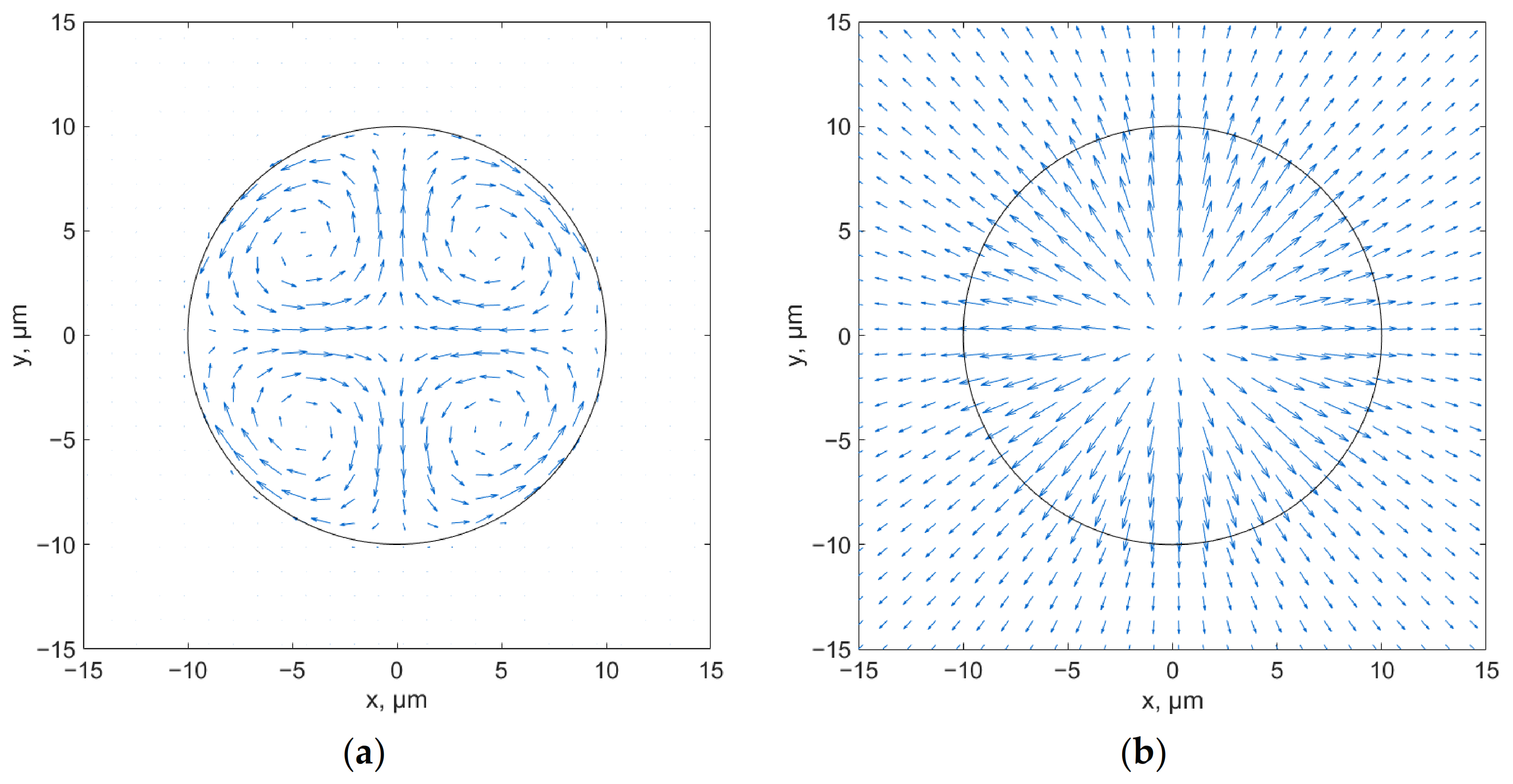
Both transverse components of the Poynting vector of the fundamental core mode for linear polarization are shown in
Figure 1. As was mentioned above, only in the presence of the core mode energy outflow is it possible to obtain a non-zero spin part of the Poynting vector as shown in Equation (6). As can be seen from
Figure 1a, the spin part of the transverse component of the Poynting vector is not equal to zero and has four singularities in the cross-section of the pipe. The orbital part of the transverse component of the Poynting vector of the fundamental core mode has a nonzero radial component, as shown in Equation (7), and therefore the energy that the mode loses when propagating through the pipe is mainly related to the orbital part (
Figure 1b). For the orbital part of the transverse component of the Poynting vector, there is only one singularity on the pipe axis.
In the case of circular polarization of the core modes, the behavior of the spin part is mainly determined by the derivatives of the intensity of the azimuthal electric field component (
Figure 2a). In this case, there is one singularity in the cross-section, which is also found at the origin. The orbital part of the transverse component of the Poynting vector of the fundamental core mode has the same behavior as in the case of linear polarization, with one singularity at the origin (
Figure 2b).
Comparing r- and ϕ-projections of spin and orbital parts of the Poynting vector, as shown in Equations (6)–(8), it can be concluded that the outflow of the core modes energy in the dielectric pipe and, correspondingly, their losses, are mainly determined by the r-projection of the orbital part. The axial energy flow of the core modes is determined by the z-projections of both spin and orbital parts of the Poynting vector.
3. Spin and Orbital Parts of the Poynting Vector of the Core Mode for ASBGFs and HFs. Low Loss Regimes
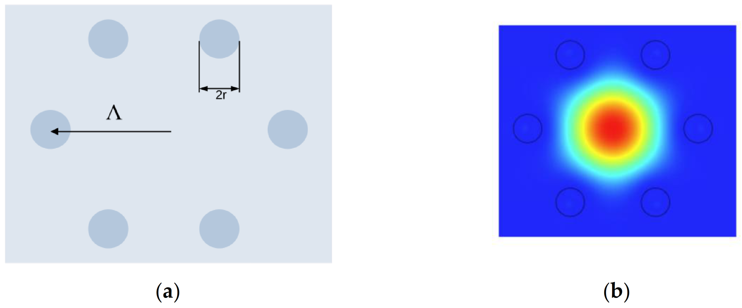
ASBGFs have one unusual feature, which is associated with the existence of such sets of geometric parameters (cladding rod radius and pitch Λ) at a given refractive index contrast between the core and the cladding rods that allow us to obtain very low loss regimes, even with a single layer of the cladding rods (
Figure 3a). Let us consider an ASBGF with the same refractive index contrast between the core and the cladding rods as in our work [
25], where n
core = 1.45 and n
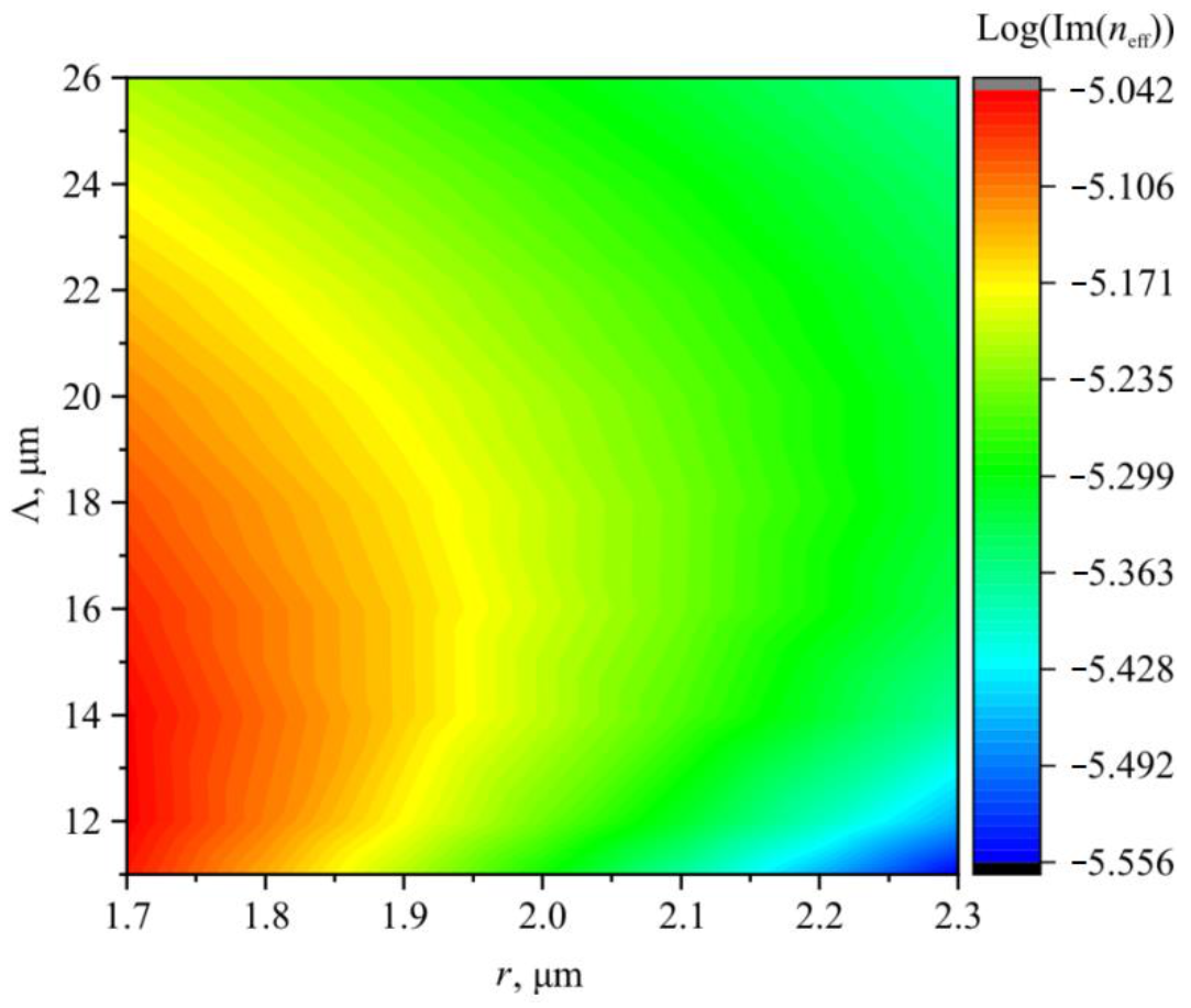
rod = 1.5, and demonstrate the loss dependence on values of the cladding rod radius and the pitch. The waveguide losses are determined by
and its dependence on the geometric parameters of the fiber is shown in
Figure 4 at a wavelength of 1 µm.
Figure 4 shows a narrow range of values of the cladding rod radius and the pitch at which the losses of the fiber fundamental core mode (
Figure 3b) fall by orders of magnitude compared to neighboring loss values. This loss behavior dependence on the geometrical parameters of the fiber cannot be explained by the reflection of the fundamental mode radiation from the cladding rods. To demonstrate this, a similar waveguide loss dependence with the same geometric parameters was calculated for an HF with a single layer of the cladding holes. The results of the calculation are shown in
Figure 5.
It can be seen from
Figure 5 that HFs with the same geometrical parameters do not have the same features in the waveguide loss dependence as the ASBGF with the waveguide loss behavior shown in
Figure 4. In this case, waveguide losses decrease monotonically with an increase in the cladding hole radius. The larger the pitch value, the larger the hole radius required to achieve a low loss level.
What is the reason for such a striking difference between the behavior of waveguide losses in ASBGFs and HFs? In order to answer this question, it is necessary to examine the behavior of the spin and orbital parts of the Poynting vector of the fundamental core mode in both types of fibers.
Let us consider the behavior of the spin and orbital parts of the transverse component of the Poynting vector of the fundamental core mode of an ASBGF with a cladding rod diameter of
r = 2 µm and Λ = 12 µm. This is a lower part of the ‘horseshoe’, displaying the low loss area (
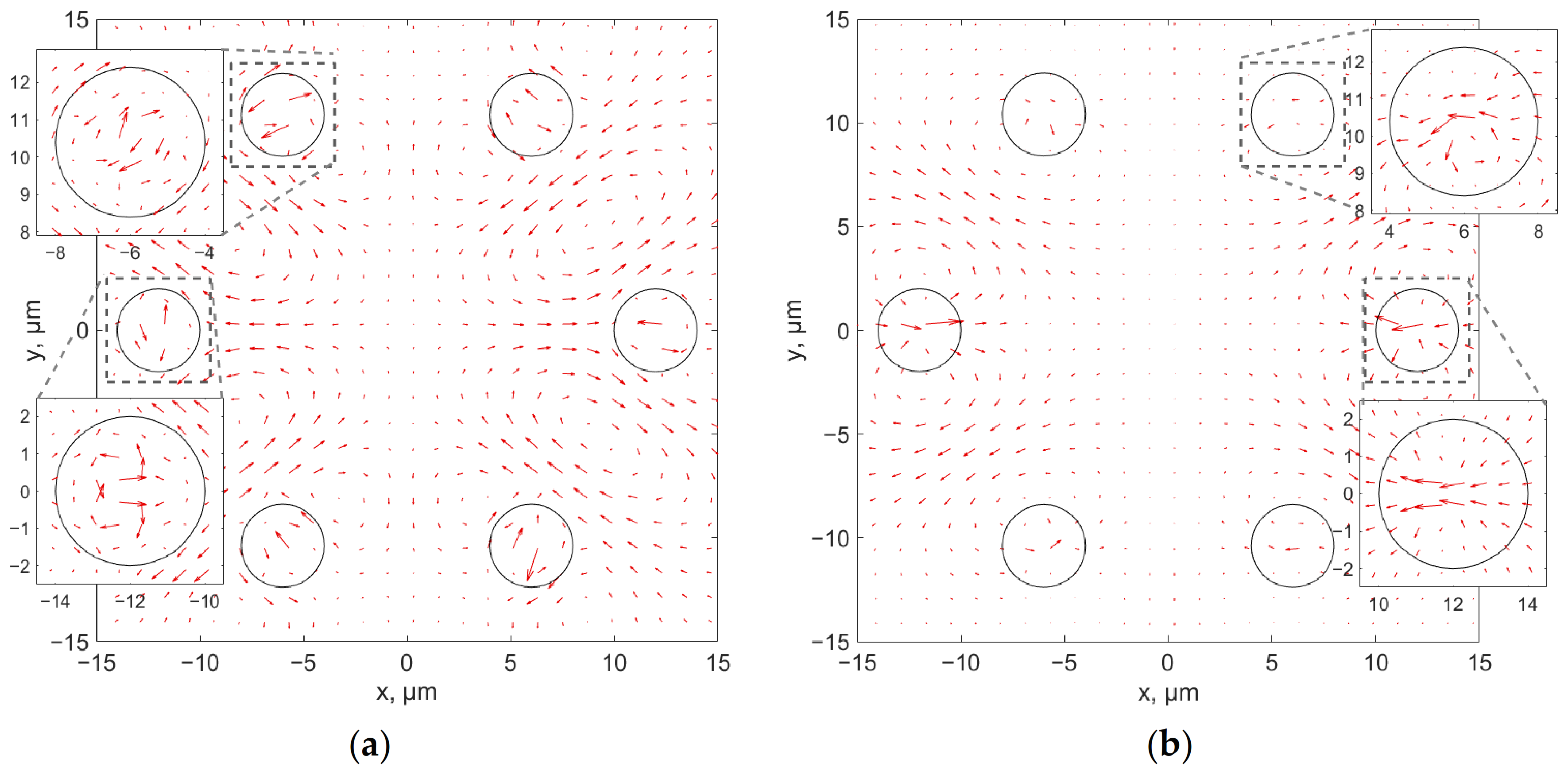
Figure 4). In this case, the waveguide loss of the ASBGF is approximately 1 dB/m. The spin and orbital parts of the transverse component of the Poynting vector are shown in
Figure 6 and
Figure 7 for the linear and circular polarization of the fundamental core mode.
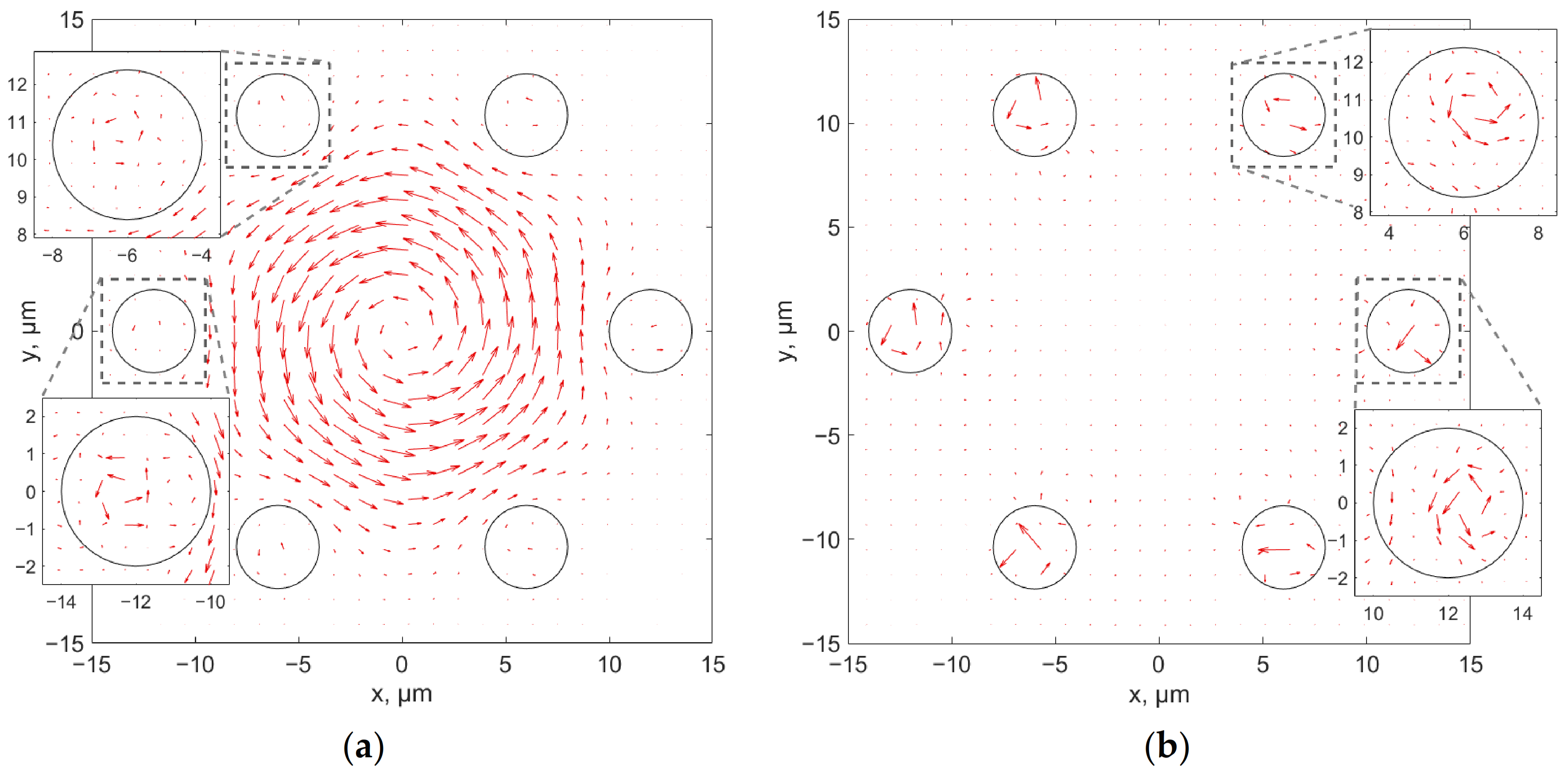
Figure 6 shows that the spin part of the Poynting vector in the case of the linear polarization of the fundamental core mode has vortex features in the cladding rods. The orbital part of the Poynting vector also has vortex features in the cladding rods, whereas, in the rods located on the Y = 0 axis, there is a strong movement of the fundamental core mode energy to the center of the fiber.
For the circular polarization of the fundamental core mode, the rotation is observed for both the spin and orbital parts of the transverse component of the Poynting vector. For the spin part of the transverse component of the Poynting vector, the rotation is carried out as in the case of a dielectric all-solid pipe (
Figure 2a) around a singularity lying on the axis of the fiber. For the orbital part of the transverse component of the Poynting vector, the rotation is carried out mainly around the singularities lying inside the cladding rods.
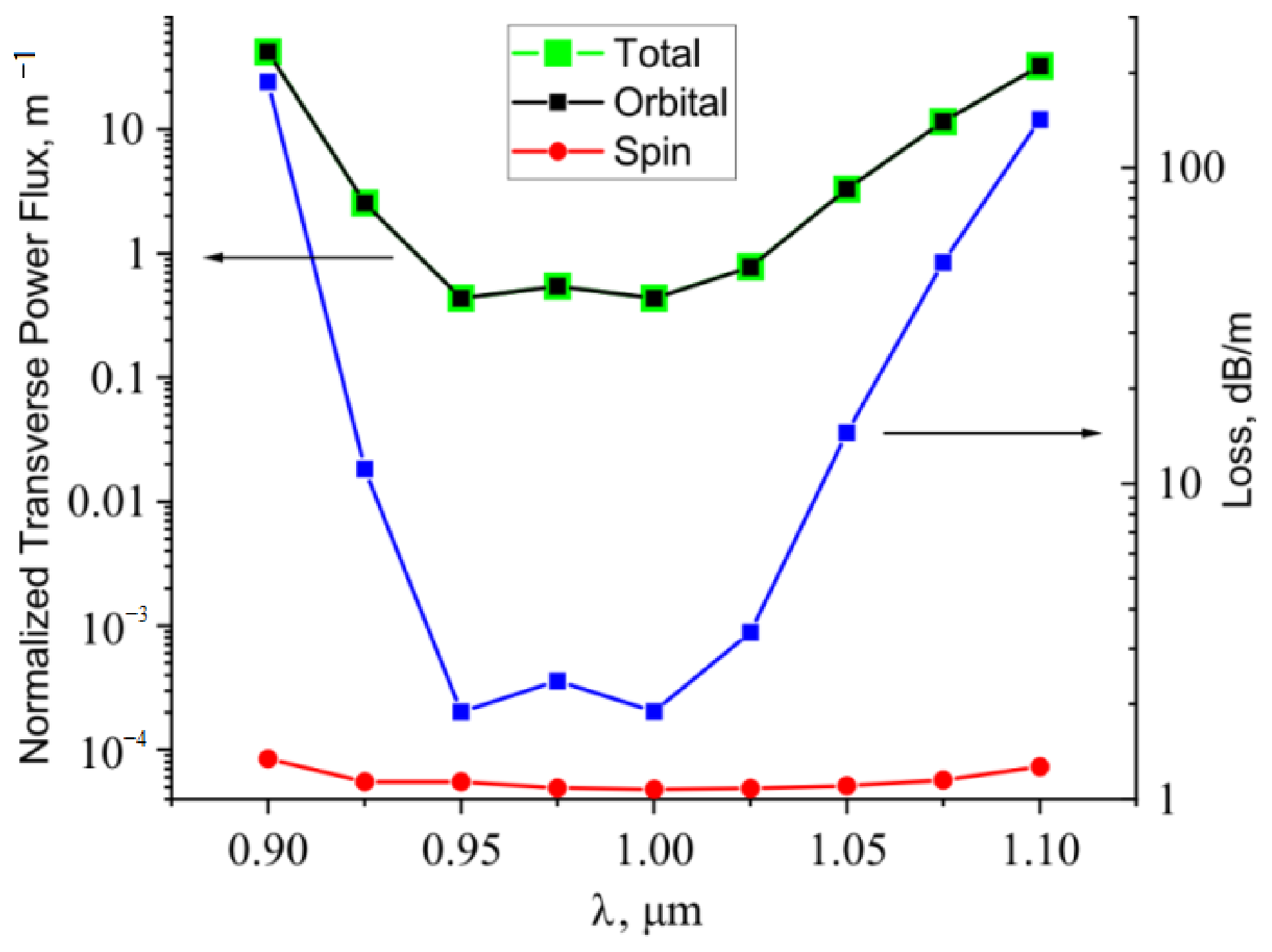
To determine which part of the flux in the case of ASBGF mostly contributes to the waveguide losses, the total flow of the spin and orbital parts of the transverse component of the Poynting vector of the fundamental core mode was calculated through the boundary of a 36 µm side square at geometric parameters of an ASBGF corresponding to the loss minimum (described above) (
Figure 4). The transverse flux was normalized to the longitudinal flux, which was considered to be equal to 1 W. Then, corresponding wavelength dependences were calculated and compared with the fiber loss in this spectral range (
Figure 8). It can be seen from
Figure 8 that waveguide losses are mainly determined by the orbital part of the transverse component of the Poynting vector of the fundamental core mode as in the case of an all-solid dielectric pipe. The spin part of the transverse component of the Poynting vector can be considered as a small correction to the waveguide losses of the fiber.
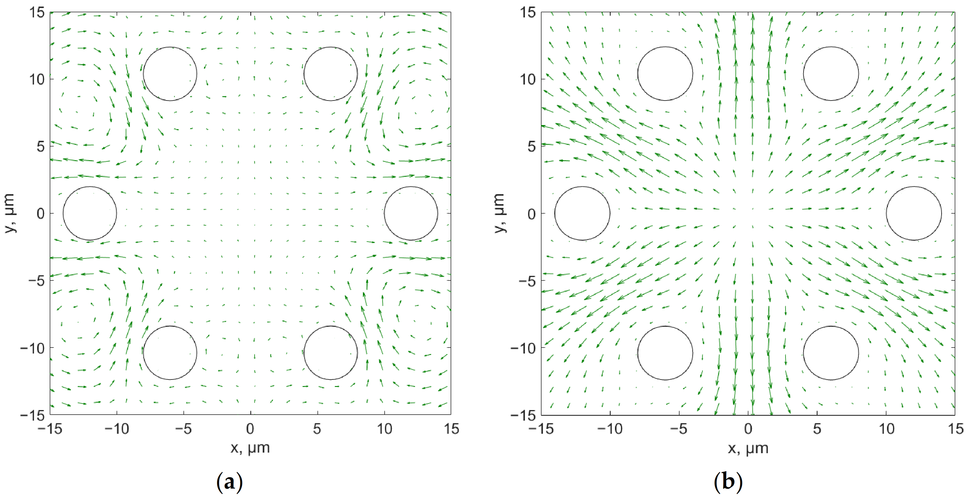
The distributions of the spin and orbital parts of the transverse component of the Poynting vector of the fundamental core mode for an HF with the same geometric parameters as for the ASBGF (waveguide loss minimum) in the case of linear polarization is shown in
Figure 9.
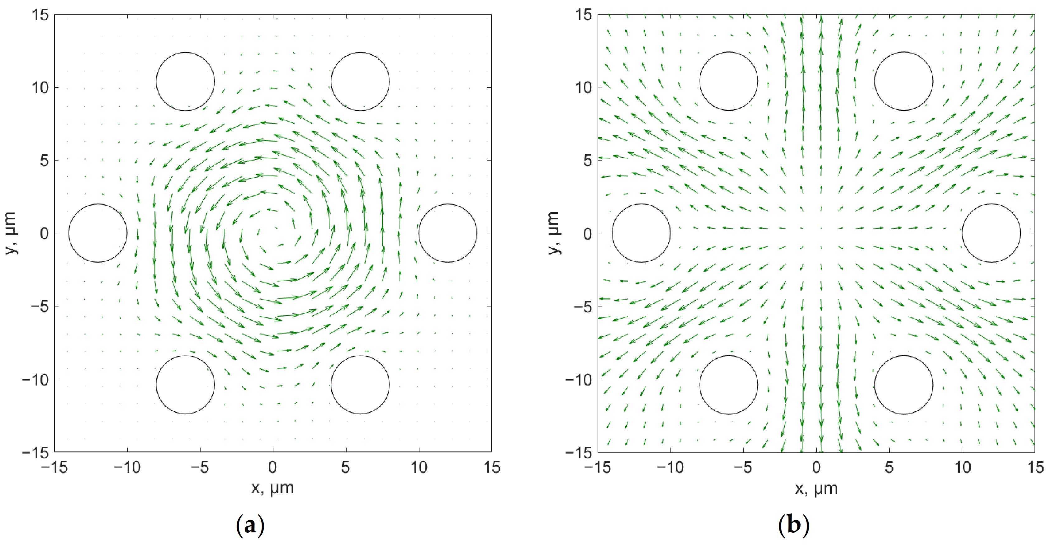
For circular polarization, the distribution of the spin and orbital parts of the Poynting vector are shown in
Figure 10. It can be seen from
Figure 9 and
Figure 10 that the spin part has a vortex configuration, whereas the orbital parts behave similarly for both polarizations and determine the mode energy outflow in the space between the cladding holes. This behavior can explain a monotonic decrease in waveguide losses in HFs (
Figure 5) when only an increase in the cladding hole radius results in a decrease in the value of the orbital part of the transverse component of the Poynting vector flowing between the holes.
In addition, an increase in the number of the cladding holes in the HF cladding will lead to a decrease in waveguide losses, but the pattern of the fundamental core mode energy leakage will not change qualitatively. In the case of an ASBGF, new vortex motions of the fundamental core mode energy will appear in the cladding rods, directing the energy to the center of the fiber.
