Abstract
A multi-wavelength erbium-doped fiber laser (MW-EDFL) with wide tuning range, switching and adjustable wavelength interval is designed and tested, which is based on a composite filter. The filter consists of a tapered microfiber coupler loop (TMCL) with a nested single mode fiber (SMF)-two mode fiber (TMF)-SMF (STS) structure, which has a comb spectrum with obvious envelope and uniform fluctuation. Our experimental and theoretical results show that the laser can output thirteen wavelengths, when the angles of two polarization controllers (PCs) in the TMCL are accurately set. Moreover, by adjusting the PCs, the tuning range of single- to sextuple-wavelength can reach about 40 nm. Six non-adjacent multi-wavelength outputs can be observed in some specific polarization states. The maximum side-mode suppression ratio (SMSR) of the output laser is 40.6 dB. Compared with other multi-wavelength EDFL, the output characteristics of the laser, such as the adjustability and flexibility of wavelength spacing and the switch-ability of wavelength number, have been improved.
1. Introduction
Nowadays, the tunable and switchable multi-wavelength EDFL is widely used in optical fiber communication systems [1]. On the one hand, multi-wavelength EDFL has more laser lines, high output power, high stability and wide tuning range [2]. On the other hand, its compact structure, better cost effectiveness and low insertion loss are impressive [3]. In addition, in practical application, compared with fixed-wavelength fiber lasers, multi-wavelength EDFL have greater value because of variable output wavelengths with adjustable spacing.
However, it is a challenge to suppress the fierce mode competition and mode jump caused by the uniform gain broadening of EDF for realize multi-wavelength EDFL. To solve these problems, people have proposed various methods, such as inserting the frequency shift devices, using optical fiber filters, adding wavelength or intensity dependent loss (PDL) structures, and using the high nonlinear effect of optical fiber [4,5]. Because the comb filter has simple structure and flexible design, researchers often use Sagnac loop mirror (SLM) interferometer, Faby-Perot (FP) filter, Mach-Zehnder interferometer (MZI), Lyot filter and others to make multi-wavelength lasers [6]. Lv et al. used a fiber filter composed of a section of three core photonic crystal fiber (TCPCF) and a section of multimode fiber (MMF), and proposed a tunable C-band and L-band 1–3 wavelength EDFL [7]. Han et al. demonstrated an adjustable all fiber comb filter with the function of accurately controlling channel spacing. The filter is composed of MZI with tapered fibers [8]. A comb filter composed of compact TMF filter is introduced by Ahmad et al. [9]. Filoteo-Razo et al. described the performance of a switchable multi-wavelength laser using a Sagnac interferometer. The laser has high stability and performance [10]. Zhao et al. used two parallel Lyot filters to build a switching EDFL that can output 1~3 wavelength with adjustable wavelength interval [11].
In this study, we implement a multi-wavelength EDFL with independent switching, wide tuning range and adjustable wavelength interval, in which a composite filter is used in the ring cavity. The composite filter is composed a TMCL with a nested STS structure. Because the STS filter is a wavelength selector based on the interference of LP01 mode and LP11 mode, the TMCL can change the range of output wavelength by adjusting the PCs. Through the composite filter, the continuous wavelength output can reach thirteen, the tuning range of multi-wavelength is 1525–1565 nm, and the non-adjacent multi-wavelength outputs can also be observed. The EDFL has many advantages, such as simple and compact structure and high stability, which can be used in optical fiber optical sensing and other fields requiring flexible light sources.
2. Principle of the Composite Filters
The TMF can support the simultaneous transmission of fundamental mode and one higher-order mode, which has attracted extensive attention of researchers in recent years. The comb filter made of TMF has the advantages of simple structure and variable period. The TMCL filter made of SMF has the advantages of easy fabrication and controllable free spectral rang (FSR). The composite filter consists of a TMCL with a nested STS structure filter, who has a comb transmission spectrum with obvious envelope and uniform fluctuation.
Figure 1b shows the schematic diagram of the composite filter. The filter is symmetrical and can be divided into left and right parts. The left half is optical microfiber coupler (OMC), which is used to divide the incident light into two parts. The right half is the combination of PC1, STS filter and PC2, which is used to output comb spectrum with small wavelength interval. The two output ports on the right side of OMC are connected together by STS to form TMCL. TMCL is used to provide envelope modulation for comb spectrum. The manufacturing process of TMCL is as follows: First, intercept a section of SMF (SMF-28e, Corning). Then, fold the SMF in half. By making a melting cone in the middle of the folded SMF, sufficient length can be reserved for the SMF at both ends to facilitate subsequent operation. Before starting the cone melting, the coating layer of the SMF shall be stripped off in the pre melting area, and one end should be fixed with the clamp of the fiber optic fused tapered machine. The two optical fibers at the other end need to be twisted by 450° and then fixed with the clamp. At the same time, the SMF is connected to broadband light source and Optical Spectrum Analyzer (OSA, YOKOGAWA, AQ6370B). Next, set appropriate melting parameters and taper the area. As the length of the cone increases gradually, the diameter of the cone becomes smaller, resulting in the FSR of TMCL becoming narrowing. Because the real-time loss and optical signal-to-noise ratio (OSNR) can be obtained by observing the spectrum, the machine can be stopped after the required FSR is obtained by observing the real-time spectrum.
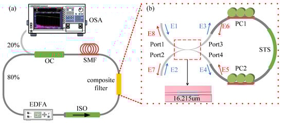
Figure 1.
(a) Schematic diagram of the proposed fiber laser based on composite filter. (b) The schematic diagram of the composite filter. EDFA: erbium-doped fiber amplifier, ISO: isolator, SMF: single mode fiber, OC: 20:80 output coupler, PC1 and PC2: polarization controllers, STS: SMF-TMF-SMF, TMF: two mode fiber.
To understand the working principle of the proposed TMCL better, we use Jones matrix to construct a simple mathematical model. When light enters the coupler from any port, because of the reduced cone core, the optical energy of the core gradually enters the cladding with the normalized frequency of the core decreases gradually, and the coupling region excites the lowest order even mode and odd mode at the same time. The power oscillation occurs in the lumbar region where the two modes propagate in. When light outputs from the other end, the normalized frequency of the optical fiber increases again in the wake of the thicker core, meanwhile, the light energy entering the cladding gradually returns to the core. Therefore, the optical energy in the two optical fibers will be coupled by fusing the cladding of the two optical fibers close enough to each other through the molten taper at the coupling region.
If the input light is E1 = 1, E2 = 0. The output light E3 and E4 passing through the taper becomes [12]:
E3 changes into input light through the loop in the clockwise direction and reversely passes through the taper, meanwhile, E4 returns to the taper in the counter-clockwise direction.
Finally, the transfer function T is:
In Equation (3), the coupling ratio of the coupler is K = sin2(CL). C = 3πλ/32n1a2(1 + 1/V)2 is the coupling coefficient between the even mode and odd mode; L represents the coupling length. CL stands for the phase difference accumulated by the two modes along the coupling length. V = 2πa(n12 − n22)0.5/λ is the normalized frequency and a is half the diameter of the cone. n1 = 1.4682 is the effective refractive index of the SMF core at 1550 nm. The transmission bandwidth of the TMCL determines the tuning range of the laser output. In order to obtain a wide tuning range, we simulated the output spectrum of the TMCL filter with parameters of L = 17,500 µm, a = 8 µm and n2 = 1. The result is shown in Figure 2a. Then we make the cone length of ~17,498.2 µm and the cone width of ~16.215 µm. The cone length is measured by the computer software of the fiber optic fused tapered machine, while the cone width is measured by a microscope. Figure 2b shows the measured output spectrum of the TMCL. The FSR of the filter can reach ~ 40 nm, which is consistent with the simulation results.
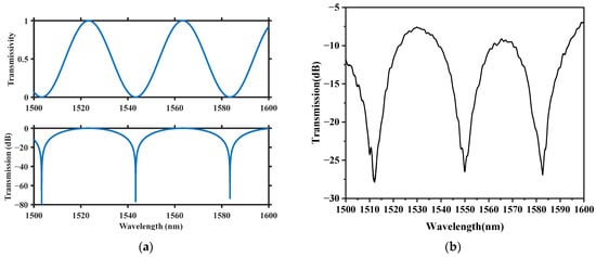
Figure 2.
(a) Simulated spectrum of the TMCL. (b) Measured transmission spectrum of the TMCL.
In order to make the composite filter, the ring area of the TMCL needs to be cut to form two additional output terminals, which are respectively connected with PC and then offset welded with the TMF (FM SI-2, YOFC) to construct STS structure. The incident light will excite LP01 mode and LP11 mode at the first splicing point when there is a slight offset fusion between the SMF and TMF, then these modes are coupled with each other and experience energy exchange. Because of the different propagation constants between the two modes, the relative phase of the light changes in the propagation process, resulting in mode interference at the second splicing point. The core diameters of SMF and TMF are 8.2 µm and 14 µm, respectively. The difference between them provides convenience for the preparation of STS.
The Jones matrix of TMF can be represented by a phase retarder [13]:
where ∆φt = πLt∆neff/λ is the linear phase difference caused by two modes in TMF and ∆neff is the effective refractive index difference between LP01 and LP11 modes. For the convenience of calculation, it is assumed that the incident light E0 passes through the biased core and is only divided into Ea of LP01 and Eb of LP11 mode:
The output light becomes , and are:
When the splitting ratio Kt = 0.5, the transmission characteristic of the STS structure filter is as follow:
In Figure 1b, the transmission matrix of PC is [14]:
E3 and E4 can return to the cone again through the loop formed by the connection of two PCs and TMF. In Equaion (8), θ represents the included angle between the polarization angle of incident light and the fast axis of TMF, which is controlled by PCs. And PCs introduce the phase delay ∆φ simultaneously. The transmission matrix of the TMF clamped in the middle of two PCs is P:
where ∆φ′ = 2πLt∆n/λ is the linear phase difference caused by TMF and ∆n is the birefringence coefficient of TMF. The light E3 of port3 changes to E5 after passing through PC1-TMF-PC2.
Similarly, the light E4 of port4 changes to E6 after passing through the path opposite to E3.
Then, the input light E6 of port3 and the input light E5 of port4 enter the conical coupler again.
The transfer function of the conical fiber coupler ring is T1 = |E7/E1|2. Finally, the transfer function of the composite filter is T = T0∙T1.
Figure 3 and Figure 4 show the simulated spectra of the composite filter in the range of 1520 nm–1570 nm under the condition of Lt = 6 m and ∆neff = 5 × 10⁻⁴. In Figure 3, the 3 dB bandwidth of the transmission spectrum changes with different θ, which accordingly influences the output characteristic of the fiber laser if the composite filter is used as wavelength selector in the cavity. When the 3 dB bandwidth of the dotted line contour is expanded, the number of output wavelengths will increase, and vice versa. In Figure 4, the transmission spectrum moves horizontally with different ∆φ, which in turn results in the tunabilty of the fiber laser. The PC-TMF-PC structure effectively induces intensity and wavelength dependent losses, and acts as an intensity equalizer [15].
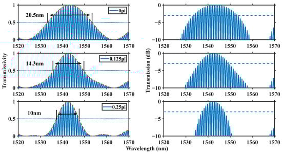
Figure 3.
Simulated spectrum of the composite filter with different θ.
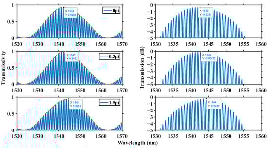
Figure 4.
Simulated spectrum of the composite filter with different ∆φ.
Figure 5 shows the measured spectra of the composite filter at different PC angles, in which the used TMF is ~5.8 m and the cone length and width are the same as mentioned above in chapter 2. The filter has a comb spectrum with ~0.8 nm wavelength interval and ~35 nm envelop interval, which is consistent with the simulation results.
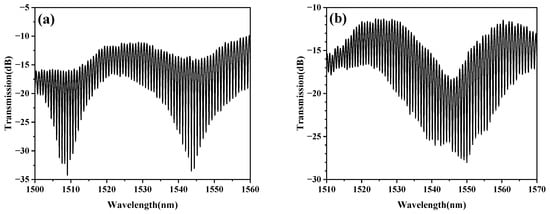
Figure 5.
Measured transmission spectra of the composite filter at different PC angles: (a) small angle, (b) large angle.
3. Experimental Setup and Results
The experimental setup of the proposed EDFL is shown in Figure 1a, which consists of an integrated gain flat erbium-doped fiber amplifier (EDFA, MCEDFA-C-20-T1, MClight), an isolator (ISO), the composite filter mentioned above, a 12 km long SMF and an 8:2 optical coupler (OC). The EDFA provides relatively flat gain. The ISO is used to ensure the unidirectional operation of the laser in the ring cavity. In order to suppress the wavelength competition in the laser cavity, a 12 km SMF is added to excite four wave mixing (FWM), so as to improve the stability of the laser output. The laser output is extracted through the 20% port of the OC and observed by OSA (AQ6370B, Yokogawa). In the experiment, the pump current of the EDFA is fixed at 1000 mA, corresponding to the maximum pump power of 121 mW.
Owing to the transmission bandwidth of the composite filter is changed with the included angle between the polarization angle of incident light and the fast axis of TMF, switchable output can be achieved by adjusting the two PCs. There are up to 13-wavelength output through adjusting the PCs. Among them, selected output spectra of single-wavelength, three-wavelength, five-wavelength, seven-wavelength, ten-wavelength and thirteen-wavelength are shown in Figure 6a–f. The side-mode suppression ratio (SMSR) of the output laser is greater than 27 dB and the maximum reaches up to 40.6 dB. The wavelength interval of multi-wavelength output is ~0.8 nm, which is consistent with the wavelength interval of the STS filter.
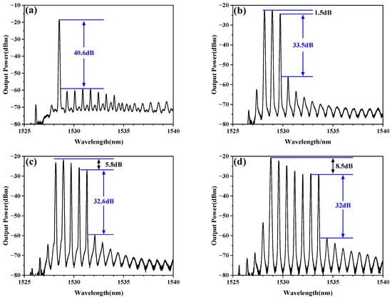
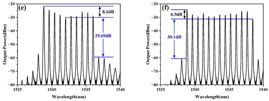
Figure 6.
Output spectra of (a) single-; (b) triple-; (c) quintuple-; (d) septuple-; (e) decuple-; (f) thirteen-wavelength.
The transmission spectrum of the composite filter influences the net gain of the cavity, which accordingly determines the lasing characteristic of the fiber laser. According to the above analysis and simulation in chapter 2, the location of the transmission spectrum can be moved through changing the polarization state. As long as two PCs are properly adjusted, the output wavelength can be tuned between 1525 nm and 1565 nm. Figure 7a–f are tunable output spectra of single-, dual-, triple-, quad-, quintuple-, and sextuple-wavelength spectra at constant pump power.
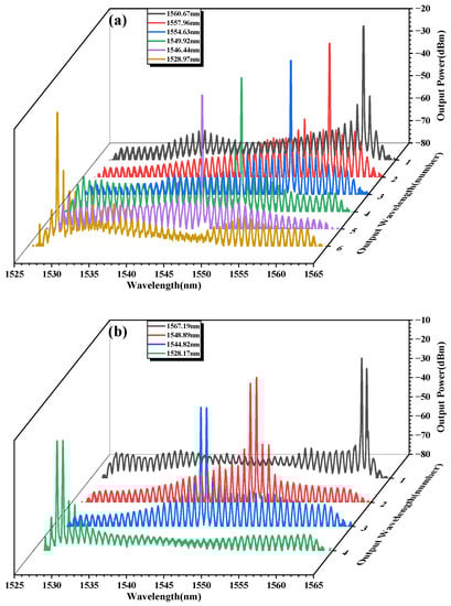
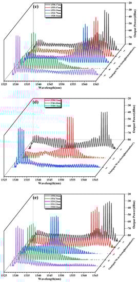
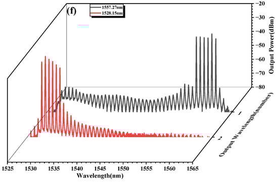
Figure 7.
Output spectra of tunable (a) single-, (b) dual-, (c) triple-, (d) quad-, (e) quintuple-, and (f) sextuple-wavelength.
Furthermore, by adjusting the two PCs in a certain range, not only the number of wavelengths and the output position of multi-wavelengths can be changed, but also non-adjacent multi-wavelengths with variable wavelength spacing can be achieved. In the adjustment process, the changes of PC1 and PC2 affect the size of the wavelength interval jointly. Figure 8a shows the output spectra of non-adjacent dual-wavelength with wavelength intervals of 8.4 nm, 21.1 nm and 33.2 nm respectively. Figure 8b shows the adjustable characteristics of non-adjacent triple-, quad-, and sextuple-wavelength. The intervals of the triple-wavelength are 14.4 nm and 17.9 nm; the intervals of quad- wavelength are 14.8 nm and 3.2 nm; and the intervals of sextuple-wavelength are 9.2 nm, 5.5 nm and 3.2 nm respectively. Due to the disturbance of the PC clamp, after 30 min, seven- and nine-wavelength lasers will have a slight displacement in the long wavelength direction, and the peak power of each wavelength will fluctuate accordingly, but the overall stability remains the same as before. It can be observed from Figure 5a that when multiple wavelengths appear in the same large envelope range, the wavelength interval is small. However, when the multi-wavelength appears in different large envelopes, the wavelength interval is larger. Therefore, the size and position of each envelope can be changed by adjusting the PCs, so that the wavelength interval can be changed accordingly. Moreover, the location of non-adjacent multi-wavelength that depends on the specific polarization state, appears almost unchanged. So, if the adjustment range is too large in the adjustment process of PCs, it will cause changes in the number of wavelengths or even the disappearance of non-adjacent multi-wavelengths.
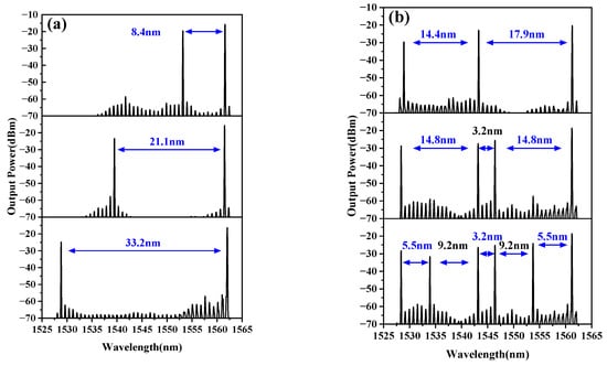
Figure 8.
Output spectra of tunable (a) dual-; (b) triple-, quad-, and sextuple-wavelength with different intervals.
In order to determine the stability of the multi-wavelength EDFL proposed at room temperature, the output spectrum of the laser was recorded several times at an interval of 5 min without adding other stable components. Figure 9a shows the wavelength and power measurement of five wavelengths within 50 min. It can be seen from the figure that the maximum wavelength displacement does not exceed 0.06 nm and the power fluctuation does not exceed 0.95 dB. Figure 9b shows the measurement results of seven wavelengths within 30 min. The results show that the wavelength shift is less than 0.06 nm and the peak power fluctuation is less than 1.9 dB. To further study the stability of multi-wavelength output, six measurements were made for nine wavelengths output, as shown in Figure 9c, which shows the maximum wavelength drift is 0.0312 nm and the maximum power drift is 1.1 dB. However, due to the sensitivity of the laser to the external environment, wavelength competition in the laser cavity, unstable pump power and uneven large envelope, it is difficult for the laser to maintain a long-term stable output at more than 13 adjacent wavelengths. In addition, if the extrusion PCs used in the experiment is replaced by programmable PCs, the stability of the laser can be optimized and the switchable laser output with switchable and adjustable characteristics can be realized more accurately.
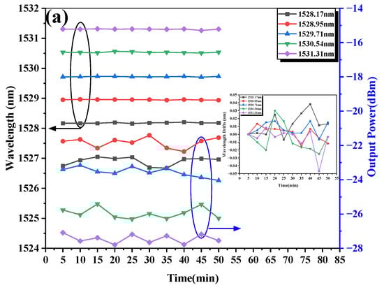
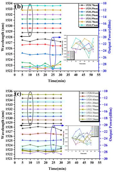
Figure 9.
The wavelength drifts (black) and power fluctuations (blue) of (a) five wavelengths; (b) seven wavelengths; (c) nine wavelengths with time interval of five minutes. Inset shows the variation of the wavelength shift with time.
4. Conclusions
In summary, a multi-wavelength EDFL with independent switching, wide tuning range and adjustable wavelength interval has been proposed and demonstrated. A composite filter is used in the ring cavity, which is composed of a TMCL with a nested STS structure filter. The composite filter has a comb spectrum with obvious envelope and uniform fluctuation. By adjusting the PCs, the fiber laser can obtain up to thirteen consecutive output wavelengths. When the number of output wavelengths is less than six, the adjustable range is 1525 nm~1565 nm. Furthermore, non-adjacent multi-wavelengths with variable wavelength spacing can also be achieved by appropriately adjusting the PCs. If the programmable PC is used to replace the mechanical PC in the experiment, the characteristics of the output laser will be further controlled. Compared with the MW-EDFL based on other filters shown in Table 1, due to the existence of TMCL, the MW-EDFL in this paper can not only change the range of output wavelength through PC, but also realize the tuning function by changing the pressure, strain, refractive index, temperature and other parameters of the environment where TMCL is located. The proposed MW-EDFL has the advantages of simple structure, low cost, good stability and wide tuning range, which can be used in various fields, such as optical sensing, wavelength division multiplexing, optical communication and so on.

Table 1.
Experimental results of stability of MWEDFL based on other filters.
Author Contributions
Conceptualization, B.S. and J.Z.; methodology, B.S. and J.Z.; software, C.L. and X.L.; validation, C.L., X.L. and J.Z.; data curation, X.L.; writing—original draft preparation, C.L.; writing—review and editing, B.S. and J.Z.; supervision, X.L. and S.Y.; project administration, J.Z.; funding acquisition, B.S. and J.Z. All authors have read and agreed to the published version of the manuscript.
Funding
This research was funded by Natural Science Foundation of Tianjin (grant number 19JCYBJC16200) and Science and Technology Program of Tianjin (grant number 20YDTPJC01530).
Institutional Review Board Statement
Not applicable.
Informed Consent Statement
Not applicable.
Data Availability Statement
The available data has been stated in the article.
Conflicts of Interest
The authors declare no conflict of interest.
References
- Merza, H.Q.; Al-Hayali, S.K.; Al-Janabi, A.H. Tunable full waveband-and adjustable spacing multi-wavelength erbium-doped fiber laser based on controlling cavity losses through bending sensitive interferometric filter. Infrared Phys. Technol. 2021, 116, 103791. [Google Scholar] [CrossRef]
- Anzueto-Sánchez, G.; Martínez-Rios, A.; Torres-Gómez, I.; Jiménez-Mares, M.; Nuñez-Gomez, R.E.; Camas-Anzueto, J.L.; Cabellos-Quiroz, J.L. Multiwavelength synchronously Q-switched Erbium-doped fiber laser based on the adjustment of the free spectral range of an intracavity tapered-fiber filter. Opt. Laser Technol. 2021, 142, 107197. [Google Scholar] [CrossRef]
- Harith, A.; Azmy, N.F.; Yusoff, N.; Reduan, S.A.; Aidit, S.N.; Bayang, L.; Samion, M.Z. MoTe2-PVA as saturable absorber for passively Q-switched thulium-doped fluoride and erbium-doped fiber laser. Optik 2021, 243, 167157. [Google Scholar]
- Tang, Z.; Liu, L.; Benson, T.; Lian, Z.; Lou, S. Dual-wavelength interval tunable and multi-wavelength switchable high-performance fiber laser based on four-leaf clover suspended core fiber filter. Opt. Laser Technol. 2021, 139, 106966. [Google Scholar] [CrossRef]
- Pan, H.; Guo, S.; Zhang, A.; Liu, C. Dual-pulse actively Q-switched fiber laser based on EOM and sagnac loop. Opt. Fiber Technol. 2021, 62, 102456. [Google Scholar] [CrossRef]
- Sulaiman, A.H.; Najamhuri, N.M.N.; Sukor, M.A.H.; Ismail, A.; Abdullah, F.; Jamaludin, M.Z. Nonlinearity Effect on Multiwavelength fiber laser based on Sagnac loop mirror interferometer. J. OptoElektronik 2021, 1, h7142c. [Google Scholar] [CrossRef]
- Lv, Y.; Lou, S.; Tang, Z.; Liu, X.; Wang, X. Tunable C-band and L-band multi-wavelength erbium-doped fiber ring laser based on a triple-core photonic crystal fiber with polarization-dependent loss. Opt. Laser Technol. 2020, 128, 106269. [Google Scholar] [CrossRef]
- Han, M.; Li, X.; Zhang, S.; Han, H.; Liu, J.; Yang, Z. Tunable and channel spacing precisely controlled comb filters based on the fused taper technology. Opt. Express 2018, 26, 265–272. [Google Scholar] [CrossRef] [PubMed]
- Ahmad, H.; Kamaruddin, N.H.; Aidit, S.N.; Samion, M.Z.; Zaini, M.K.A.; Bayang, L.; Wang, Y.; Wang, S.; Sahu, J.K.; Yasin, M. Multi-wavelength Bismuth-doped fiber laser in 1.3 µm based on a compact two-mode fiber filter. Opt. Laser Technol. 2021, 144, 107390. [Google Scholar] [CrossRef]
- Filoteo-Razo, J.D.; Hernandez-Garcia, J.C.; Estudillo-Ayala, J.M.; Pottiez, O.; Jauregui-Vazquez, D.; Sierra-Hernandez, J.M.; Lauterio-Cruz, J.P.; Carrillo-Delgado, C.M.; Rojas-Laguna, R. Multi-wavelength Er–Yb-doped fibre ring laser using a double-pass Mach–Zehnder interferometer with a Sagnac interferometer. Opt. Laser Technol. 2021, 139, 106994. [Google Scholar] [CrossRef]
- Zhao, Q.; Pei, L.; Zheng, J.; Tang, M.; Xie, Y.; Li, J.; Ning, T. Switchable multi-wavelength erbium-doped fiber laser with adjustable wavelength interval. J. Lightwave Technol. 2019, 37, 3784–3790. [Google Scholar] [CrossRef]
- Zhao, L.; Zhang, Y.; Chen, Y.; Wang, J. Simultaneous measurement of temperature and RI based on an optical microfiber coupler assembled by a polarization maintaining fiber. Appl. Phys. Lett. 2019, 114, 151903. [Google Scholar] [CrossRef]
- Chen, J.; Lu, P.; Liu, D.; Zhang, J.; Wang, S.; Chen, D. Optical fiber curvature sensor based on few mode fiber. Optik 2014, 125, 4776–4778. [Google Scholar] [CrossRef]
- Zhao, Q.; Pei, L.; Zheng, J.; Tang, M.; Xie, Y.; Li, J.; Ning, T. Tunable and interval-adjustable multi-wavelength erbium-doped fiber laser based on cascaded filters with the assistance of NPR. Opt. Laser Technol. 2020, 131, 106387. [Google Scholar] [CrossRef]
- Feng, X.; Tam, H.; Wai, P. Stable and uniform multiwavelength erbium-doped fiber laser using nonlinear polarization rotation. Opt. Express 2006, 14, 8205–8210. [Google Scholar] [CrossRef] [PubMed]
- Zhao, Q.; Pei, L.; Zheng, J.; Tang, M.; Xie, Y.; Li, J.; Ning, T. Switchable, Widely Tunable and Interval-Adjustable Multi-Wavelength Erbium-Doped Fiber Laser Based on Cascaded Filters. J. Lightwave Technol. 2020, 38, 2428–2433. [Google Scholar] [CrossRef]
- Zhao, Q.; Pei, L.; Ruan, Z.; Zheng, J.; Wang, J.; Tang, M.; Li, J.; Ning, T. Tunable and wavelength interval precisely controlled erbium-doped fiber laser by employing the fused taper technology. Chin. Opt. Lett. 2022, 20, 011402. [Google Scholar] [CrossRef]
- Chang, Y.; Pei, L.; Ning, T.; Zheng, J.; Li, J.; Xie, C. Switchable and tunable multi-wavelength fiber ring laser employing a cascaded fiber filter. Opt. Fiber Technol. 2020, 58, 102240. [Google Scholar] [CrossRef]
- Chang, Y.; Pei, L.; Ning, T.; Zheng, J. Switchable multi-wavelength fiber laser based on hybrid structure optical fiber filter. Opt. Laser Technol. 2020, 124, 105985. [Google Scholar] [CrossRef]


Publisher’s Note: MDPI stays neutral with regard to jurisdictional claims in published maps and institutional affiliations. |
© 2022 by the authors. Licensee MDPI, Basel, Switzerland. This article is an open access article distributed under the terms and conditions of the Creative Commons Attribution (CC BY) license (https://creativecommons.org/licenses/by/4.0/).