Abstract
White organic light-emitting diodes (WOLEDs) incorporating a blend of blue, green and red phosphorescent small molecular materials are presented in this article. 4,4′,4″-Tris(carbazol-9-yl)triphenylamine (TcTa) and 9-(4-tert-Butylphenyl)-3,6-bis(triphenylsilyl)-9H-carbazole (CzSi) with different transmission characteristics were selected as hosts for different emitting layers aim to promote holes transport, which will reinforce carriers’ balance and broaden carrier composite. On account of adaptive energy levels of the utilized dopants and hosts, secured phosphorescent WOLED displayed high efficiencies, low operating voltage and slow efficiency roll-off. In addition, distribution of carriers’ recombination zone and spectral of change were studied in detail to further understand the light-emitting mechanisms of obtained WOLEDs. Finally, by majorizing the dosage concentration of (fbi)2Ir(acac) (bis(2-(9,9-diethyl-9H-fluoren-2-yl)-1-phenyl-1H-benzoimidazol-N,C3)iridium(acetylacetonate)) and the architectures of WOLEDs, the optimal device exhibited the maximum efficiencies of 44.92 cd A−1, 42.85 lm W−1, 16.8%, respectively, turn on voltage of 2.6 V and Commission International de l’Eclairage coordinates of (0.337, 0.458) at the brightness level of 3000 cd m−2.
1. Introduction
White organic light-emitting diodes (WOLEDs) have achieved intense attention because of their unique features such as environment-friendly lighting source, easy-flexibility, good color rendering index and physiological friendly in flat panel displays and lighting fields [1,2,3,4,5,6,7]. To accomplish high performance WOLEDs, three primary (e.g., red, green, blue) or two adscititious (e.g., blue, orange or yellow) dyes are indispensable. At present, fluorescent and phosphorescent hybrid WOLEDs that integrate stable blue fluorescent and red/green/orange phosphorescent emitters have realized certain success in relatively high efficiency and excellent stability [8,9,10,11,12,13]. Whereas, to obtain high electroluminescent (EL) efficiency, it is necessary to design reasonable device structure and select matched blue fluorescent materials with high photo-luminescent quantum yields (PLQYs). Generally, the fabrication of phosphorescent WOLEDs, which possess inherent 4-fold higher efficiency than those of fluorescent diodes since all excitons could be effectively utilized, is particularly desired [14,15,16,17,18]. Multiple EMLs structures are often used to physically separate two or more phosphorescent materials with different colors from each other. To realize white light, the thickness of each emitting layer should to be designed skillfully and the doping concentration of guests should be accurately adjusted. However, the design of multi-emitting-layers WOLEDs will also leads to the complexity of device fabrication and difficulty in adjusting the emitting spectrum.
Therefore, the general challenge in designing multilayer WOLEDs is ensuring the balanced emissions from different emitting layers. Meanwhile, being able to exactly regulate the thickness of each layer and achieving low dopant concentrations of lower energy emitters are crucial to realize balanced white light. Recently, tremendous efforts have been made to develop WOLEDs. For instance, Zhu et al. fabricated the multi-emitting-layers WOLEDs with slow decay of efficiency only 1.8% at practical brightness level of 1000 cd m−2 by constructing reasonable emissive layer to make full use of carriers [19]. Miao and co-works designed high performances hybrid WOLEDs with three ultrathin phosphorescent emitting layers and one blue fluorescent emitting layer. Finally, the optimal multilayer WOLED exhibited high external quantum efficiency (EQE) close to 20% and high CRI of 90 [20]. To satisfy the requirements of practical application, multi-emitting-layers WOLEDs are expected to be also efficient in improving efficiency and slowing the attenuation of efficiency [21,22,23].
According to our previous work, warm white device with simple structure was prepared by employing trace doping technology based on typical orange thermally activated delayed fluorescent material 2,3,5,6-tetrakis(3,6-diphenyl-carbazol-9-yl)benzene (4CzTPN-Ph) through skillfully controlling the contribution ratio of carrier trapping in the device. However, relatively low device performances with CEmax, PEmax and EQEmax of 32.33 cd A−1, 32.75 lm W−1 and 10.2% were obtained, respectively [24]. To increase WOLED performances, we designed the white OLEDs based on three phosphorescent iridium complexes FIrpic (iridium(III)bis[(4,6-difluorophenyl)pyridinato-N,C20′]picolinat, blue emitter), Ir(mppy)3 (tris(2-(4-tolyl)-phenylpyridine)iridium, green emitter) and (fbi)2Ir(acac) ((bis(2-(9,9-diethyl-9H-fluoren-2-yl)-1-phenyl-1H-benzoimidazol-N,C3)iridium (acetylacetonate), orange-red emitter). In this case, these three iridium complexes were utilized as the dopants because of their excellent luminescent efficiencies. The experiment results made clear that adaptive energy levels of dopants and hosts exert a beneficial impact on broadening carrier composite and motivating the balance of carriers. Therefore, the optimal device displayed turn-on voltage of 2.6 V, maximum current efficiency of 44.92 cd A−1, power efficiency of 42.85 lm W−1, EQE of 16.8%, and CIE coordinates of (0.337, 0.458) at the brightness level of 3000 cd m−2. With increasing current density from 10 to 100 mA cm−2, CIE changed gradually from (0.337, 0.458) to (0.292, 0.438).
2. Materials and Methods
The dopants of FIrpic, Ir(mppy)3, (fbi)2Ir(acac) and functional materials of TAPC, TcTa, CzSi, Tm3PyP26PyB were obtained commercially and used directly. Patterned indium-tin-oxide (ITO) glass (10 Ω sq−1) was taken as the anode which were cleaned and rinsed with abluent and ultra-pure water, respectively, after that put it into an oven dried at 120 °C for 60 min before film deposition. Organic layers were continuously deposited at the rate of 1 Å s−1 in a specialized organic vacuum chamber (≤2.0×10⁻⁵ Pa). All of the EMLs were manufactured by using co-doping technology from two or three separate evaporator sources. Afterward, the devices were transferred to another vacuum chamber (≤8.0×10⁻⁵ Pa) through a transition rod to deposit LiF and Al at rates of 0.1 and 10 Å s−1, respectively. The thicknesses of organic or metal films and the rate of materials used in these devices were monitored with crystal oscillator sensors. An ultrathin metal mask was made into determining cathode position and preparing eight 9 mm2 emitting dots for device performances testing. The overall electroluminescent performances, absorption spectra and photoluminescence (PL) spectra were measured with Brightness Light Distribution Characteristics Measurement System C9920-11, Shimadzu UV-3600 and Hitachi F-7000 fluorescence spectrophotometer, respectively.
3. Results and Discussion
To enhance the utilization probability of excitions, realize 100% internal quantum efficiency and thus achieve white emission device with slow efficiency roll-off, it is crucial to deftly construct device structure by selecting suitable materials. As depicted in Figure 1, device configuration and HOMO/LUMO levels diagram, 1,4,5,8,9,11-hexaazatriphenylene hexacarbonitrile (HAT-CN) and LiF serve as anode and cathode interface modified layers to ameliorate the injection of holes and electrons, respectively [25]. We used p-type HAT-CN (0.2 wt%) doped into di-[4-(N,N-ditolyl-amino)-phenyl]cyclohexane (TAPC) and 1,3,5-tris(6-(3-(pyridin-3-yl)phenyl)pyridin-2-yl) (Tm3PyP26PyB) as hole transport layer (HTL) and electron transport layer to improve hole mobility from p-doping technology and achieve highly effective transport of electrons [26,27]. FIrpic, Ir(mppy)3 and (fbi)2Ir(acac) with high photoluminescent quantum yields (PLQYs) and matched energy levels were selected as three emitters [17,28,29]. For these three elements WOLEDs, 4,4’,4’’-tri(9-carbazoyl)triphenylamine (TcTa) and 9-(4-tert-Butylphenyl)-3,6-bis (triphenylsilyl)-9H-carbazole (CzSi) were chosen as the host materials for their complementary transport types [30,31]. The triplet energies (T1) of TcTa and CzSi are 2.83 and 3.02 eV, respectively, while those of (fbi)2Ir(acac), Ir(mppy)3 and FIrpic are 2.20, 2.38 and 2.62 eV, respectively. In this case, the T1 of TcTa and CzSi are more than adequate to restrict triplet excitons on emitter molecules and hinder from the back transmission of triplet exciton energy from emitter to host. Thus, using TcTa as the host of EML1 and EML2 is beneficial for the transmission of holes. The utilization of bipolar host CzSi helps to facilitate carriers’ balance and broaden recombination zone. The structures of FIrpic, Ir(mppy)3, (fbi)2Ir(acac), and other organic functional materials used in these WOLED are given in Scheme S1.
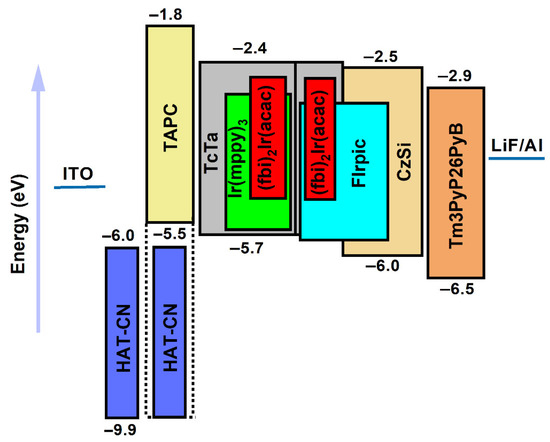
Figure 1.
The WOLEDs device structure researched in this paper and the energy level of the used materials.
The absorption spectra of (fbi)2Ir(acac), Ir(mppy)3 and FIrpic, and the PL spectra of Ir(mppy)3, FIrpic, TcTa and CzSi in dichloromethane (CH2Cl2) were measured and illustrated in Figure 2. The PL spectra of Ir(mppy)3, FIrpic, TcTa and CzSi peaked at 517, 484, 395 and 376 nm, respectively. Interestingly, metal-to-ligand charge transfer bands from singlet (1MLCT) and triplet (3MLCT) are clearly resolved at 405 and 460 nm for (fbi)2Ir(acac), 410 and 470 nm for Ir(mppy)3, 380 and 420 nm for FIrpic, respectively [32,33]. Simultaneously, large segistration between absorption spectra of guests and emission spectra of hosts was observed, which means efficient energy transmission from hosts to guests is feasible. In addition, obvious segistration between the emission spectrum of FIrpic and the absorption spectra of (fbi)2Ir(acac) and Ir(mppy)3 indicated that energy transmission from blue to red and green emitters is possible. However, PL spectrum of Ir(mppy)3 has no marked segistration with absorption spectrum of (fbi)2Ir(acac), indicating energy transmission from Ir(mppy)3 to (fbi)2Ir(acac) is impossible.
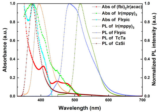
Figure 2.
Absorption spectra of (fbi)2Ir(acac), Ir(mppy)3, FIrpic and PL spectra of Ir(mppy)3, FIrpic, TcTa and CzSi measured in CH2Cl2.
To determine the concentration of (fbi)2Ir(acac), a set of co-doped single-EML ((fbi)2Ir(acac) (x wt%):Ir(mppy)3 (10 wt%):TcTa (10 nm)) and double-EMLs ((fbi)2Ir(acac) (x wt%):Ir(mppy)3 (10 wt%):TcTa (10 nm)/(fbi)2Ir(acac) (x wt%):FIrpic (18 wt%):CzSi (8 nm)) devices with the structures of ITO/HAT-CN (6 nm)/HAT-CN (0.2 wt%):TAPC (50 nm)/single-EML or double-EMLs/Tm3PyP26PyB (60 nm)/LiF (1 nm)/Al (100 nm) were firstly prepared by adjusting x from 1 to 3 with interval of 1. Tables S1 and S2, in Supporting Information, summarized the key EL performance parameters of these devices. As shown in Figures S1a,b and S2a,b, in Supporting Information, for single-EML devices, when the dosage concentration of (fbi)2Ir(acac) was 1 wt%, the green emission intensity is higher than that of red emission, indicating that most carriers recombined on Ir(mppy)3 molecules. In regard to double-EMLs devices, weak blue emission was observed. So, blue emission ratio should be enhanced to achieve white emission.
Then, based on common ETL, HTL and electrode interface modified layers in the device mentioned above, Device W1 with the EML structure of (fbi)2Ir(acac) (1 wt%):Ir(mppy)3 (10 wt%):TcTa (7 nm)/(fbi)2Ir(acac) (1 wt%):FIrpic (18 wt%):TcTa (3 nm)/FIrpic (18 wt%):CzSi (8 nm) was manufactured and examined. With the insertion of blue emitting layer, which is constructed by doping FIrpic into CzSi film, not only device performances were improved but also the blue emission ratio was increased significantly. Device W1 procured the maximum current efficiency (CEmax) of 66.97 cd A−1, power efficiency (PEmax) of 59.47 lm W−1, external quantum efficiency (EQEmax) of 24.4% and CIE coordinates of (0.260, 0.436) at the brightness of 3000 cd m−2. Meanwhile, as depicted in Figure 3, greenish-white and bluish-white light was obtained by Device W1 at relatively low and high current densities, respectively. Three characteristic emissions centered at 471, 507 and 556 nm originating from FIrpic, Ir(mppy)3 and (fbi)2Ir(acac), respectively, were observed. Simultaneously, blue and red emission in EL spectra exhibited a large variation with increasing current density. Based on Device W1, Device W2 was fabricated with the increased dosage concentration of (fbi)2Ir(acac) within EML1 to be 2 wt%. As shown in Figure 4, with aggrandizing dosage concentration of (fbi)2Ir(acac) within EML1, more carriers were recombined in red emitter, the relative intensities of red emission increased obviously but still dissatisfied with the requirement of standard white emission.
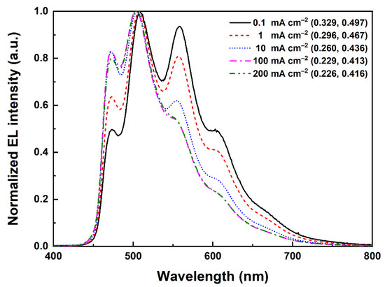
Figure 3.
Normalized EL spectra of device W1 operating at different current densities.
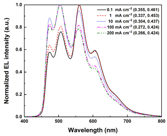
Figure 4.
Normalized EL spectra of device W2 operating at different current densities.
To further enhance the intensity ratios of red and blue emissions, the dosage concentration of (fbi)2Ir(acac) within EML2 was adjusted to be 1.4 wt% based on Device W2. Surprisingly, the obtained device (Device W3) achieved higher EL efficiency and brightness compared with Device W2 mainly due to the broadening recombination zone. As illustrated in Figure 5, the intensity ratios of blue and green emissions in Device W3 were lower than those of Device W2. At low current density, red emission intensity is the highest one among the three emissions in Device W3. Importantly, with the increasing current density, blue emission increased gradually, while red emission decreased slightly. At the same time, it is presumed that the recombination center is near the interface between 7 nm (fbi)2Ir(acac) (2 wt%):Ir(mppy)3 (10 wt%):TcTa and 3 nm (fbi)2Ir(acac) (1.4 wt%):FIrpic (18 wt%):TcTa layers rather than near the interface between 3 nm (fbi)2Ir(acac) (1.4 wt%):FIrpic (18 wt%):TcTa and 8 nm FIrpic (18 wt%):CzSi layers. Carriers were firstly captured by the orange-red (fbi)2Ir(acac) molecules near the interface between 7 nm (fbi)2Ir(acac) (2 wt%):Ir(mppy)3 (10 wt%):TcTa and 3 nm (fbi)2Ir(acac) (1.4 wt%):FIrpic (18 wt%):TcTa layers, then diffused into Ir(mppy)3 (10 wt%):TcTa and FIrpic (18 wt%):CzSi emitting layers and were captured by Ir(mppy)3 and FIrpic molecules. Device W3 obtained the CEmax of 44.92 cd A−1, PEmax of 42.85 lm W−1, EQEmax of 16.8%, which are higher than those of reported works in Table S3, in supporting information [34,35,36], maximum brightness (Bmax) of 38,150 cd m−2 and CIE coordinates of (0.337, 0.458) at the brightness of 3000 cd m−2.
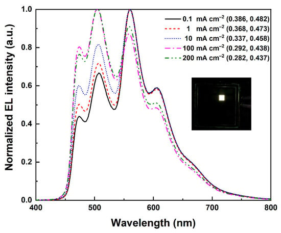
Figure 5.
Normalized EL spectra of device W3 operating at different current densities.
Continuously, the doping concentrations of (fbi)2Ir(acac) within EML1 and EML2 were modulated to be 2.4 wt% and 0.6 wt%, respectively, and the obtained device was defined as Device W4. As shown in Figure 6, the intensity ratios of blue and green emissions in Device W4 were higher than those of Device W3, while the intensity ratio of red emission decreased in some degree compared with Device W3. The CIE coordinates of Device W4 is (0.283, 0.415) at 10 mA cm−2. Finally, based on Device W4, the concentration of (fbi)2Ir(acac) within EML1 was modulated to be 3.0 wt%, and the obtained device was defined as Device W5. With the increment of current density, as illustrated in Figure 7, the intensity ratios of blue and green emissions have no marked change, while the intensity ratio of red emission dropped gradually. CIE coordinates of Device W5 is (0.211, 0.388) at 10 mA cm−2.
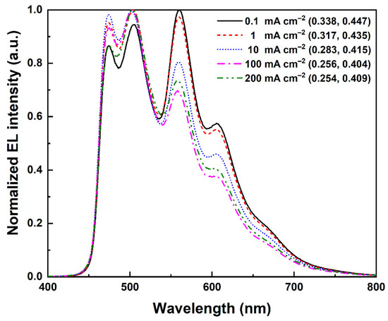
Figure 6.
Normalized EL spectra of device W4 operating at different current densities.
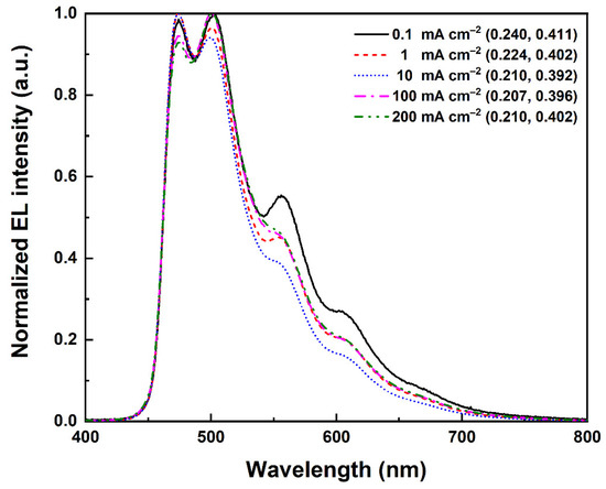
Figure 7.
Normalized EL spectra of device W5 operating at different current densities.
To prove the emission zone is located near the interface between 7 nm (fbi)2Ir(acac) (2 wt%):Ir(mppy)3 (10 wt%):TcTa and 3 nm (fbi)2Ir(acac) (1.4 wt%):FIrpic (18 wt%):TcTa layers rather than the interface between 3 nm (fbi)2Ir(acac) (1.4 wt%):FIrpic (18 wt%):TcTa and 8 nm FIrpic (18 wt%):CzSi layers, as well as lower energy gap increased carriers’ smoothly transport. Then, Device W6 with the EML structure of Ir(mppy)3 (10 wt%):TcTa (7 nm)/(fbi)2Ir(acac) (0.2 nm)/FIrpic (18 wt%):TcTa (3 nm)/FIrpic (18 wt%):CzSi (8 nm) was further designed and compared. As shown in Figure 8, the intensity ratios of blue and green emissions increased gradually with adding current density from 0.1 to 200 mA cm−2. Interestingly, as the current density of Device W6 leaps to 100 and 200 mA cm−2, the relative intensity of red emission tends to drop, plausibly because the recombination zone located near the interface between 7 nm (fbi)2Ir(acac) (2 wt%):Ir(mppy)3 (10 wt%):TcTa and 3 nm (fbi)2Ir(acac) (1.4 wt%):FIrpic (18 wt%):TcTa layers. So, carriers are firstly captured by (fbi)2Ir(acac) molecules, and then transported to 7 nm Ir(mppy)3 (10 wt%):TcTa and 8 nm FIrpic (18 wt%):CzSi emitting layers. The CIE coordinates of Device W6 are (0.317, 0.438) at 10 mA cm−2. Simultaneously, Figure 9 compared the EL efficiency-current density (η-J) characteristics and current density-brightness-voltage (J-B-V) characteristics of Devices W1-W6. In addition, these WOLEDs exhibited slow efficiency roll-off as depicted in Figure S3, in Supporting Information.
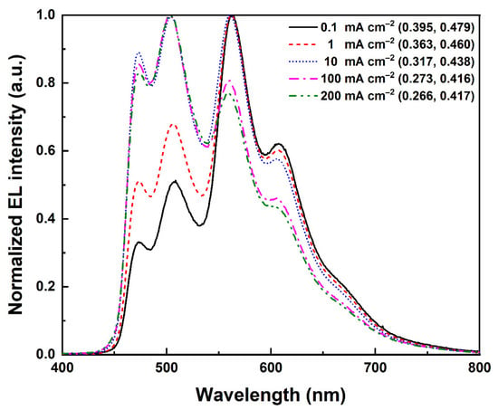
Figure 8.
Normalized EL spectra of device W6 operating at different current densities.
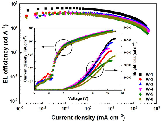
Figure 9.
EL efficiency-current density (η-J) characteristics of devices W1-W6. Inset: Current density-brightness-voltage (J-B-V) characteristics of devices W1-W6.
Furthermore, the PL spectra of 30 nm (fbi)2Ir(acac) (2 wt%):Ir(mppy)3 (10 wt%):TcTa and (fbi)2Ir(acac) (1 wt%):FIrpic (18 wt%):TcTa films were depicted in Figure 10 to better understand the photo-physical properties of these three-elements WOLEDs. Clearly, these two films exhibit the typical emissions of FIrpic (473 nm), Ir(mppy)3 (507 nm) and (fbi)2Ir(acac) (560 nm). Compared with the EL spectra of Device W3 as depicted in Figure 4, the peaks of blue, green and orange-red emissions were consistent with their EL spectra, which indicates the well energy transfer within Device W3, which caused the high performances.
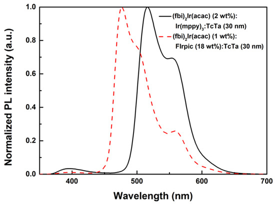
Figure 10.
Normalized PL spectra of 30 nm (fbi)2Ir(acac) (2 wt%):Ir(mppy)3 (10 wt%):TcTa film and 30 nm (fbi)2Ir(acac) (1 wt%):FIrpic (18 wt%):TcTa film.
4. Conclusions
In summary, highly efficient WOLEDs with slow efficiency roll-off have been designed and fabricated by selecting host materials and three phosphorescent emitters with well-matched triplet energies and energy levels. Importantly, the change of EL spectra at different dosage of red emitter in different emitter and location of EL recombination zone were analysed in detail. By majorizing dosage concentration of orange-red emitter and structure of devices, the optimal WOLED obtained the CEmax, PEmax and EQEmax up to 44.92 cd A−1, 42.85 lm W−1 and 16.8%, respectively. At the practical brightness level of 1000 cd m−2, the same device exhibited the CE of 38.05 cd A−1 (EQE = 14.28%), PE of 28.46 lm W−1, and CIE of (0.357, 0.468).
Supplementary Materials
The following supporting information can be downloaded at: www.mdpi.com/article/10.3390/photonics9100767/s1, Scheme S1: The molecular structures of organic materials used in this work.; Table S1: The key properties of single-EML devices with different doping concentrations of (fbi)2Ir(acac).; Figure S1: (a) EL efficiency-current density (η-J) characteristics of single-EML devices with (fbi)2Ir(acac) at different doping concentrations. Inset: Current density-brightness-voltage (J-B-V) characteristics of single-EML devices with (fbi)2Ir(acac) at different doping concentrations. (b) Normalized EL spectra of single-EML devices with (fbi)2Ir(acac) at different doping concentrations operating at 10 mA cm−2.; Table S2: The key properties of double-EMLs devices with different doping concentrations of (fbi)2Ir(acac).; Figure S2: (a) EL efficiency-current density (η-J) characteristics of double-EMLs devices with (fbi)2Ir(acac) at different doping concentrations. Inset: Current density-brightness-voltage (J-B-V) characteristics of double-EMLs devices with (fbi)2Ir(acac) at different doping concentrations. (b) Normalized EL spectra of double-EMLs devices with (fbi)2Ir(acac) at different doping concentrations operating at 10 mA/cm2.
Author Contributions
Conceptualization, L.Z.; methodology, L.Z.; investigation, R.W.; data curation, R.W. and X.L.; writing—original draft preparation, R.W.; writing—review and editing, W.L. and L.Z.; supervision, W.L. and L.Z.; funding acquisition, L.Z. All authors have read and agreed to the published version of the manuscript.
Funding
Please add: This research was funded by the financial aid from Research Equipment Development Project of Chinese Academy of Sciences (YJKYYQZ20200005), and National Natural Science Foundation of China (62174160).
Institutional Review Board Statement
Not applicable.
Informed Consent Statement
Not applicable.
Data Availability Statement
The data presented in this study are available in article here.
Conflicts of Interest
The authors declare no conflict of interest.
References
- D’Andrade, B.W.; Forrest, S.R. White organic light-emitting devices for solid-state lighting. Adv. Mater. 2004, 16, 1585–1595. [Google Scholar] [CrossRef]
- D’Andrade, B.W.; Thompson, M.E.; Forrest, S.R. Controlling exciton diffusion in multilayer white phosphorescent organic light emitting devices. Adv. Mater. 2002, 14, 147–151. [Google Scholar] [CrossRef]
- Kido, J.; Kimura, M.; Nagai, K. Multilayer white light-emitting organic electroluminescent device. Science 1995, 267, 1332–1334. [Google Scholar] [CrossRef] [PubMed]
- Su, S.J.; Gonmori, E.; Sasabe, H.; Kido, J. Highly efficient organic blue-and white-light-emitting devices having a carrier-and exciton-confining structure for reduced efficiency roll-off. Adv. Mater. 2008, 20, 4189–4194. [Google Scholar] [CrossRef]
- Sasabe, H.; Kido, J. Development of high performance OLEDs for general lighting. J. Mater. Chem. C 2013, 1, 1699–1707. [Google Scholar] [CrossRef]
- Wu, Z.; Ma, D. Recent advances in white organic light-emitting diodes. Mat. Sci. Eng. R 2016, 107, 1–42. [Google Scholar] [CrossRef]
- Zhao, F.; Ma, D. Approaches to high performance white organic light-emitting diodes for general lighting. Mater. Chem. Front. 2017, 1, 1933–1950. [Google Scholar] [CrossRef]
- Liu, W.; Chen, Z.; Zheng, C.J.; Liu, X.K.; Wang, K.; Li, F.; Dong, Y.P.; Ou, X.M.; Zhang, X.H. A novel nicotinonitrile derivative as an excellent multifunctional blue fluorophore for highly efficient hybrid white organic light-emitting devices. J. Mater. Chem. C 2015, 3, 8817–8823. [Google Scholar] [CrossRef]
- Liu, X.K.; Chen, W.; Thachoth Chandran, H.; Qing, J.; Chen, Z.; Zhang, X.H.; Lee, C.S. High-performance, simplified fluorescence and phosphorescence hybrid white organic light-emitting devices allowing complete triplet harvesting. ACS Appl. Mater. Inter. 2016, 8, 26135–26142. [Google Scholar] [CrossRef]
- Miao, Y.; Zhao, B.; Gao, Z.; Shi, H.; Tao, P.; Wu, Y.; Wang, K.; Wang, H.; Xu, B.; Zhu, F. A novel intramolecular charge transfer blue fluorophor for high color stability hybrid di-chromatic white organic light-emitting diodes. Org. Electron. 2017, 42, 1–7. [Google Scholar] [CrossRef]
- Cao, C.; Chen, W.C.; Chen, J.X.; Yang, L.; Wang, X.Z.; Yang, H.; Huang, B.; Zhu, Z.L.; Tong, Q.X.; Lee, C.S. Bipolar blue host emitter with unity quantum yield allows full exciton radiation in single-emissive-layer hybrid white organic light-emitting diodes. ACS Appl. Mater. Inter. 2019, 11, 11691–11698. [Google Scholar] [CrossRef] [PubMed]
- Liu, Y.; Liang, F.; Cui, L.S.; Shi, X.B.; Wang, Z.K. Simplified hybrid white organic light-emitting diodes with a mixed fluorescent blue emitting layer for exciton managing and lifetime improving. Adv. Opt. Mater. 2016, 4, 2051–2056. [Google Scholar] [CrossRef]
- Duan, L.; Tsuboi, T.; Qiu, Y. Highly efficient hybrid white tandem organic light-emitting diodes with MoO3 layer. Chin. J. Chem. 2015, 33, 859–864. [Google Scholar] [CrossRef]
- Ulbricht, C.; Beyer, B.; Friebe, C.; Winter, A.; Schubert, U.S. Recent developments in the application of phosphorescent iridium (III) complex systems. Adv. Mater. 2009, 21, 4418–4441. [Google Scholar] [CrossRef]
- Chang, Y.; Song, Y.; Wang, Z.; Helander, M.; Qiu, J.; Chai, L.; Liu, Z.; Scholes, G.; Lu, Z. Highly efficient warm white organic light-emitting diodes by triplet exciton conversion. Adv. Funct. Mater. 2013, 23, 705–712. [Google Scholar] [CrossRef]
- Lai, S.L.; Tao, S.L.; Chan, M.Y.; Ng, T.W.; Lo, M.F.; Lee, C.S.; Zhang, X.H.; Lee, S.T. Efficient white organic light-emitting devices based on phosphorescent iridium complexes. Org. Electron. 2010, 11, 1511–1515. [Google Scholar] [CrossRef]
- Reineke, S.; Lindner, F.; Schwartz, G.; Seidler, N.; Walzer, K.; Lüssem, B.; Leo, K. White organic light-emitting diodes with fluorescent tube efficiency. Nature 2009, 459, 234–238. [Google Scholar] [CrossRef] [PubMed]
- Zhao, J.; Yuan, S.; Du, X.; Li, W.; Zheng, C.; Tao, S.; Zhang, X. White OLEDs with an EQE of 21% at 5000 cd m-2 and ultra high color stability based on exciplex host. Adv. Opt. Mater. 2018, 6, 1800825. [Google Scholar] [CrossRef]
- Zhu, L.; Wu, Z.; Chen, J.; Ma, D. Reduced efficiency roll-off in all-phosphorescent white organic light-emitting diodes with an external quantum efficiency of over 20%. J. Mater. Chem. C 2015, 3, 3304–3310. [Google Scholar] [CrossRef]
- Miao, Y.; Wang, K.; Zhao, B.; Gao, L.; Tao, P.; Liu, X.; Hao, Y.; Wang, H.; Xu, B.; Zhu, F. High-efficiency/CRI/color stability warm white organic light-emitting diodes by incorporating ultrathin phosphorescence layers in a blue fluorescence layer. Nanophotonics 2018, 7, 295–304. [Google Scholar] [CrossRef]
- Sun, N.; Wang, Q.; Zhao, Y.; Yang, D.; Zhao, F.; Chen, J.; Ma, D. A hybrid white organic light-emitting diode with above 20% external quantum efficiency and extremely low efficiency roll-off. J. Mater. Chem. C 2014, 2, 7494–7504. [Google Scholar] [CrossRef]
- Chen, Y.; Sun, Q.; Dai, Y.; Yang, D.; Qing, X.; Ma, D. High efficiency blue and color-stable hybrid warm white organic light-emitting diodes based on a thermally activated delayed fluorescent material as an assistant host. J. Mater. Chem. C 2020, 8, 13777–13785. [Google Scholar] [CrossRef]
- Miao, Y.; Wang, K.; Gao, L.; Zhao, B.; Wang, Z.; Zhao, Y.; Zhang, A.; Wang, H.; Hao, Y.; Xu, B. Combining emissions of hole-and electron-transporting layers simultaneously for simple blue and white organic light-emitting diodes with superior device performance. J. Mater. Chem. C 2018, 6, 1853–1862. [Google Scholar] [CrossRef]
- Cui, Y.; Jiang, Y.; Zhou, L.; Liu, W.; Zhu, Q.; Zhang, H. High performance organic light-emitting diodes with tunable color range from orange to warm white based on single thermally activated delayed fluorescence emitter. Opt. Mater. 2018, 85, 349–355. [Google Scholar] [CrossRef]
- Lin, H.W.; Lin, W.C.; Chang, J.H.; Wu, C.I. Solution-processed hexaazatriphenylene hexacarbonitrile as a universal hole-injection layer for organic light-emitting diodes. Org. Electron. 2013, 14, 1204–1210. [Google Scholar] [CrossRef]
- Lee, J.; Chopra, N.; Eom, S.H.; Zheng, Y.; Xue, J.; So, F.; Shi, J. Effects of triplet energies and transporting properties of carrier transporting materials on blue phosphorescent organic light emitting devices. Appl. Phys. Lett. 2008, 93, 348. [Google Scholar] [CrossRef]
- Ye, H.; Chen, D.; Liu, M.; Su, S.J.; Wang, Y.F.; Lo, C.C.; Lien, A.; Kido, J. Pyridine-containing electron-transport materials for highly efficient blue phosphorescent OLEDs with ultralow operating voltage and reduced efficiency roll-off. Adv. Funct. Mater. 2014, 24, 3268–3275. [Google Scholar] [CrossRef]
- Xie, H.Z.; Liu, M.W.; Wang, O.Y.; Zhang, X.H.; Lee, C.S.; Hung, L.S.; Lee, S.T.; Teng, P.F.; Kwong, H.L.; Zheng, H.; et al. Reduction of self-quenching effect in organic electrophosphorescence emitting devices via the use of sterically hindered spacers in phosphorescence molecules. Adv. Mater. 2001, 13, 1245–1248. [Google Scholar] [CrossRef]
- Huang, H.; Wang, Y.; Zhuang, S.; Yang, X.; Wang, L.; Yang, C. Simple phenanthroimidazole/carbazole hybrid bipolar host materials for highly efficient green and yellow phosphorescent organic light-emitting diodes. J. Phys. Chem. C 2012, 116, 19458–19466. [Google Scholar] [CrossRef]
- Ikai, M.; Tokito, S.; Sakamoto, Y.; Suzuki, T.; Taga, Y. Highly efficient phosphorescence from organic light-emitting devices with an exciton-block layer. Appl. Phys. Lett. 2001, 79, 156–158. [Google Scholar] [CrossRef]
- Tsai, M.H.; Ke, T.H.; Lin, H.W.; Wu, C.C.; Chiu, S.F.; Fang, F.C.; Liao, Y.L.; Wong, K.T.; Chen, Y.H.; Wu, C.I. Triphenylsilyl-and trityl-substituted carbazole-based host materials for blue electrophosphorescence. ACS Appl. Mater. Inter. 2009, 1, 567–574. [Google Scholar] [CrossRef] [PubMed]
- Wang, Q.; Ding, J.; Ma, D.; Cheng, Y.; Wang, L.; Jing, X.; Wang, F. Harvesting excitons via two parallel channels for efficient white organic LEDs with nearly 100% internal quantum efficiency: Fabrication and emission-mechanism analysis. Adv. Funct. Mater. 2009, 19, 84–95. [Google Scholar] [CrossRef]
- Fukagawa, H.; Shimizu, T.; Kamada, T.; Kiribayashi, Y.; Osada, Y.; Hasegawa, M.; Morii, K.; Yamamoto, T. Highly efficient and stable phosphorescent organic light-emitting diodes utilizing reverse intersystem crossing of the host material. Adv. Opt. Mater. 2014, 2, 1070–1075. [Google Scholar] [CrossRef]
- Hong, W.; Chi, L.; Chen, W.; Chen, Y.; Chou, S.; Wong, K. A new benzimidazole/carbazole hybrid bipolar material for highly efficient deep-blue electrofluorescence, yellow-green electrophosphorescence, and two-color-based white OLEDs. J. Mater. Chem. 2010, 20, 10113–10119. [Google Scholar] [CrossRef]
- Yang, X.; Zheng, S.; Bottger, R.; Chae, H.; Tanaka, T.; Li, S.; Mochizuki, A.; Jabbour, G. Efficient fluorescent deep-blue and hybrid white emitting devices based on carbazole/benzimidazole compound. J. Phys. Chem. C 2011, 115, 14347–14352. [Google Scholar] [CrossRef]
- Wang, X.; Zhang, S.; Liu, Z.; Yue, S.; Zhang, Z.; Chen, Y.; Xie, G.; Xue, Q.; Zhao, Y.; Liu, S. Hybrid white organic light-emitting diodes with improved color stability and negligible efficiency roll-off based on blue fluorescence and yellow phosphorescence. J. Lumin. 2013, 137, 59–63. [Google Scholar] [CrossRef]
Publisher’s Note: MDPI stays neutral with regard to jurisdictional claims in published maps and institutional affiliations. |
© 2022 by the authors. Licensee MDPI, Basel, Switzerland. This article is an open access article distributed under the terms and conditions of the Creative Commons Attribution (CC BY) license (https://creativecommons.org/licenses/by/4.0/).