Communication

D2-Filled Hollow-Core Fiber Gas Raman Laser at 2.15 μm

1
College of Advanced Interdisciplinary Studies, National University of Defense Technology, Changsha 410073, China
2
Nanhu Laser Laboratory, National University of Defense Technology, Changsha 410073, China
3
State Key Laboratory of Pulsed Power Laser Technology, Changsha 410073, China
*
Author to whom correspondence should be addressed.
Photonics 2022, 9(10), 753; https://doi.org/10.3390/photonics9100753
Submission received: 20 August 2022 / Revised: 1 October 2022 / Accepted: 9 October 2022 / Published: 11 October 2022
(This article belongs to the Section Lasers, Light Sources and Sensors)

Abstract

:
Fiber lasers around 2 µm band have attractive applications, such as coherent detecting, material processing, pump source for mid-IR lasers based on nonlinear frequency shift, etc. Fiber gas Raman lasers (FGRLs) based on the stimulated Raman scattering of the gas molecules filled in the hollow-core fibers (HCFs) have been proved an efficient method to enrich the wavelengths of fiber lasers. In this paper, we demonstrated a deuterium-filled fiber gas Raman laser working at 2147 nm. The pump laser is directly coupled into the HCF through the fusion splice between the HCF and the solid-core fiber. By adjusting the pressure, fiber length as well as the repetition frequency of the 1971 nm pump laser, a maximum average Raman power of ~2.57 W was obtained, with corresponding efficiency of ~40%. This work provides a simple and compact configuration for 2.1 µm fiber lasers, which is significant for their application.

1. Introduction

Lasers at 2 μm band have attractive applications for their gorgeous properties. For example, it is located in the transmission window of the atmosphere, which helps realize communication [1] and the measurement of atmospheric environment [2,3,4]; it is an ideal pump source for generating terahertz pulses [5] as well as mid-infrared lasers [6,7,8]; lasers at this band also have significant advantages in material processing [9].
Generally, 2 μm band fiber lasers are generated through the holmium-doped fiber lasers (HDFLs) and thulium-doped fiber lasers (TDFLs) [10,11,12]. However, due to the enormously decreasing absorption as well as emission cross section of Tm3+ and Ho3+ [13], the wavelengths of TDFLs and HDFLs could be hardly expanded to beyond 2.1 μm. Complicated laser system possesses great challenge to the heat management of HDFL and TDFL, besides, various nonlinear effects such as stimulated Raman scattering and self-phase modulation, would lead to spectral broadening under high pump power [14], which restricts their applications for some research such as coherent detection where a narrow-linewidth laser is necessary.
Fiber gas Raman lasers (FGRLs) have been proved a novel and efficient method to enrich the wavelengths of fiber lasers since the first report in 2002 [15,16]. In the past decades, FGRLs ranging over 1–4 μm have been reported based on the SRS of hydrogen, methane, carbon dioxide, etc. [17,18,19,20,21,22,23,24,25,26,27]. However, there have no report concerning 2.1 μm band FGRLs.
In this paper, based on the pure rotational SRS of deuterium molecules, we demonstrate an efficient fiber gas Raman laser. The pump laser is directly coupled to the HCF by the fusion splice between the solid-core fiber and hollow-core fiber to increase the stability of the laser system. We carefully studied the factors (including fiber length, pressure, repetition frequency and pumping pulse width) which could possess great impact to Raman power. Pumped by a 1.5 MHz, 10 ns pulse laser, a maximum Raman power of 2.57 W of 2.15 μm Raman laser is obtained at the pressure of 26.5 bar when the fiber (HCF) length is 16.8 m. The corresponding optical to optical conversion efficiency is 40%. The Raman power and conversion efficiency could be further improved by reducing the splicing loss. This work provides a novel and efficient method to generate 2.1 μm band fiber lasers, which also is of great significance for the development of FGRLs.

2. Materials and Methods

The whole fiber laser system is displayed in Figure 1. We divide the system to three parts: pump source, hollow-core fibers and measuring system, which will be carefully described in following subsections.

2.1. Pump Source

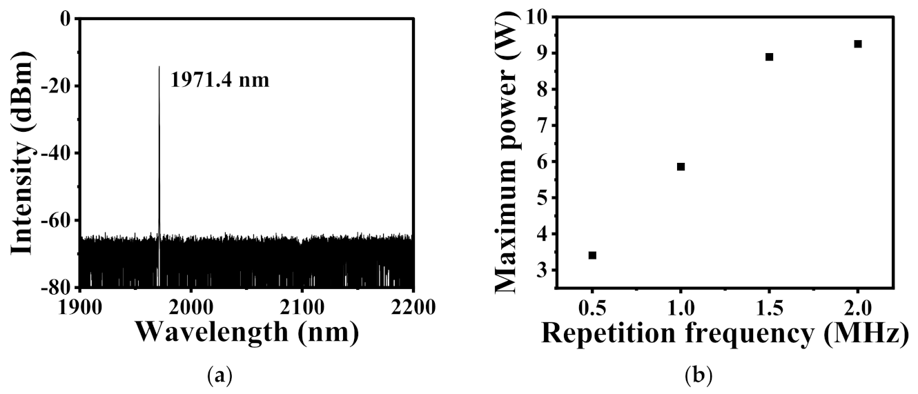
The pump source contains a seed laser (AP-TM-165, Advance Photonics), a pulse modulator (Rainbow-2000-NS, NPI Lasers) and a thulium-doped fiber amplifier (TDFA) (TDFA-HP, NPI Lasers). A continuous-wave 1971 nm laser is generated by the seed laser, which is then converted to pulse laser by the modulator (repetition frequency ranges from 0.5–2 MHz, pulse width ranges from 10–30 ns). Figure 2a shows the spectrum of the seed laser. The pump power is amplified by the TDFA, due to the safety restrictions of the amplifier, the maximum pump power is different according to the repetition frequency, which is displayed in Figure 2b.

2.2. Hollow-Core Fibers

A scanning image of the cross section of the HCF (HCF-2000-01, NKT PHOTONICS) in our experiment is displayed in Figure 3a, the measured core diameter is ~14 μm. It can be seen from Figure 3b that hollow-core fiber in our experiment have low transmission loss at both 1.97 μm (0.075 dB/m) and 2.15 μm (0.21 dB/m). A 0.5-m-long single-mode solid-core fiber (SMF 10–125, NUFERN) is spliced to the HCF, and the splice loss (marked as splice 1 in Figure 1) is estimated to be ~1.42 dB. We chose SMF 10–125 because the mode field diameter (MFD) of this fiber is similar to that of HCF-2000-01, which can reduce the splice loss caused by the mismatch of MFD. The other end of the HCF is sealed in a gas cell which can help vacuum the system as well as fill it with D2. The length of the HCF is a variable in our experiment.

2.3. Measuring System

The measuring system contains optical lens and mirrors, which are framed in Figure 1. After collimating the output laser through the lens, we can get the spectrum by the OSA (AQ6375B, YOKOGAWA) through the laser reflected by the silver mirror. The filter (FB2250-500, THORLABS) helps separate the pump and Raman lasers so we can respectively measure the Raman power and residual pump power precisely. The pulse train is detected by an InGaAs detector (2 µm InGaAs PIN Detector ET-5000, Electro-Optics Technology).

3. Results and Discussion

3.1. Spectrum Characteristics

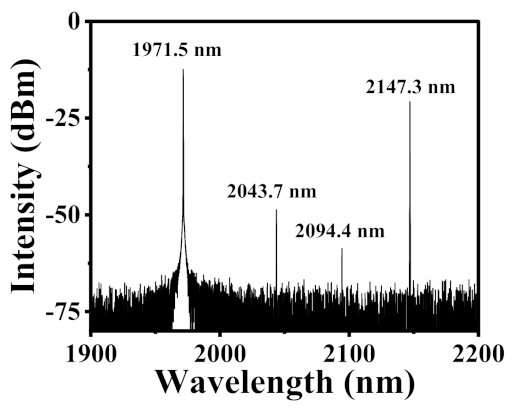
With a fiber length of 16.8 m and a deuterium pressure of 26.5 bar, when the pump source (repetition frequency set to 1.5 MHz, pulse width set to 10 ns) generates a maximum output, the output spectrum is measured as plotted in Figure 4. It can be seen that the pump laser is converted to three 1st order Raman lines, and each Raman line attributes to one Raman frequency shift: the Raman frequency shift for 2043.7 nm, 2094.4 nm and 2147.3 nm is ~178 cm−1, ~298 cm−1 and 414 cm−1. However, among these three Raman lines, the 2147 nm Raman laser dominates the output Raman power, that is because the D2 population on J = 2 level is significantly higher than those on J = 0, and 1 levels, and Raman gain coefficient is proportional to the population density on the specified level. Therefore, the intensity of 2147 nm is 20 dB higher than that of the other two Raman lines. When we increase the incident pump power, this Raman line (2147 nm) is first converted, thus “Raman power” in our article referring to the power of 2147 nm Raman laser.

3.2. Pulse Shape

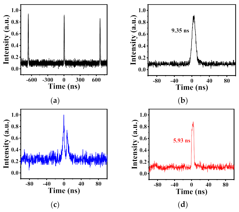
By introducing the filter (FB2250-500), we have access to measuring the pulse profile of both the pump and Raman lasers, as shown in Figure 5. The pump pulse in Figure 5a,b is observed before Raman conversion occurs. The pulses in Figure 5c,d are obtained under the condition described in Figure 4 (at a maximum output Raman power with a fiber length of 16.8 m and a deuterium pressure of 26.5 bar, pumped by 1.5 MHz 10 ns pulse laser). It can be seen that the measured pulse width of the Raman laser (5.93 ns) is narrower than that of the pump laser, and there is an apparent dip in the pulse shape of the residual pump power displayed in Figure 5c. That is because only the part of the pump laser which exceeds the threshold could be converted to Raman lasers. The results go well with previous research [19]. Moreover, the Raman pulse duration is likely to increase with the coupled pump power increasing, because a larger part of the pump pulse is above the threshold for Raman conversion [28].

3.3. Power Performance

In order to make the statement more understanding, we introduce several formats below. P is the peak power of the pump laser, and Pave represents the average pump power. f and t represent the repetition frequency and pulse width of the pump laser respectively. Pth (gas Raman threshold) and Raman gain coefficient are given as Equations (2) and (3) respectively [27,29].
P = Pave/f/t
P t h = A e f f g α p G + α s L 1 e x p α p L
g = 2 λ s 2 h v s Δ N π Δ v σ Ω
A e f f is the effective fiber modal field, L is the fiber length, α p and α s are the fiber loss for pump and Raman laser, respectively. G is the net gain factor related to measurement condition. λ s is the wavelength of Raman laser, h v s is the energy per Stokes photon, Δ N is the population difference within the interaction region between the initial and final states, which is proportional to gas pressure, Δ v is the width of the Raman gain profile, σ / Ω is the differential cross section for Raman scattering.
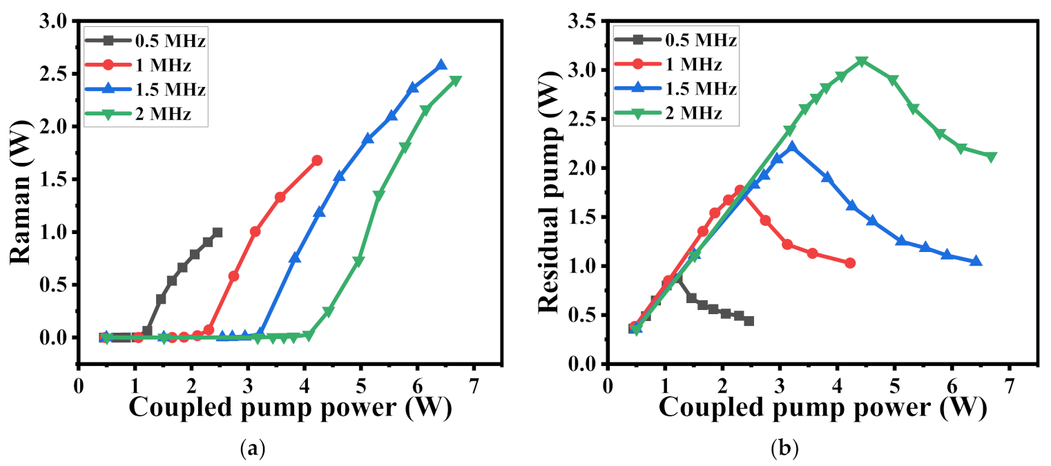
The evolution of Raman power with coupled pump power is plotted in Figure 6. By adjusting the repetition frequency, a maximum Raman power of 2.57 W is obtained with a deuterium pressure of 26.5 bar and a fiber (HCF) length of 16.8 m. The corresponding optical to optical conversion efficiency (Raman power/coupled pump power*100%) is 40%, while the total efficiency is only 29%. This data could be improved by optimizing the loss of Splice 1 and the fiber (HCF) length. When the repetition frequency is higher than 0.5 MHz, the pump laser has lower peak power (inversely proportional to the repetition rate, Equation (1)), thus causing an increase of the average pump power that is necessary to exceed the Raman threshold. Therefore, we can see that more pump power is needed to generate Raman laser with the repetition frequency increasing. Although the peak power is lower at the repetition frequency of 1.5 MHz and 2 MHz, the available pump power is much higher than that of 0.5 MHz and 1 MHz as shown in Figure 2b, thus the Raman power at these two repetition frequencies (1.5 MHz and 2 MHz) is much higher than the other. In the latter part of our paper, all of the Raman power is obtained at a repetition frequency of 1.5 MHz except those specially noted.
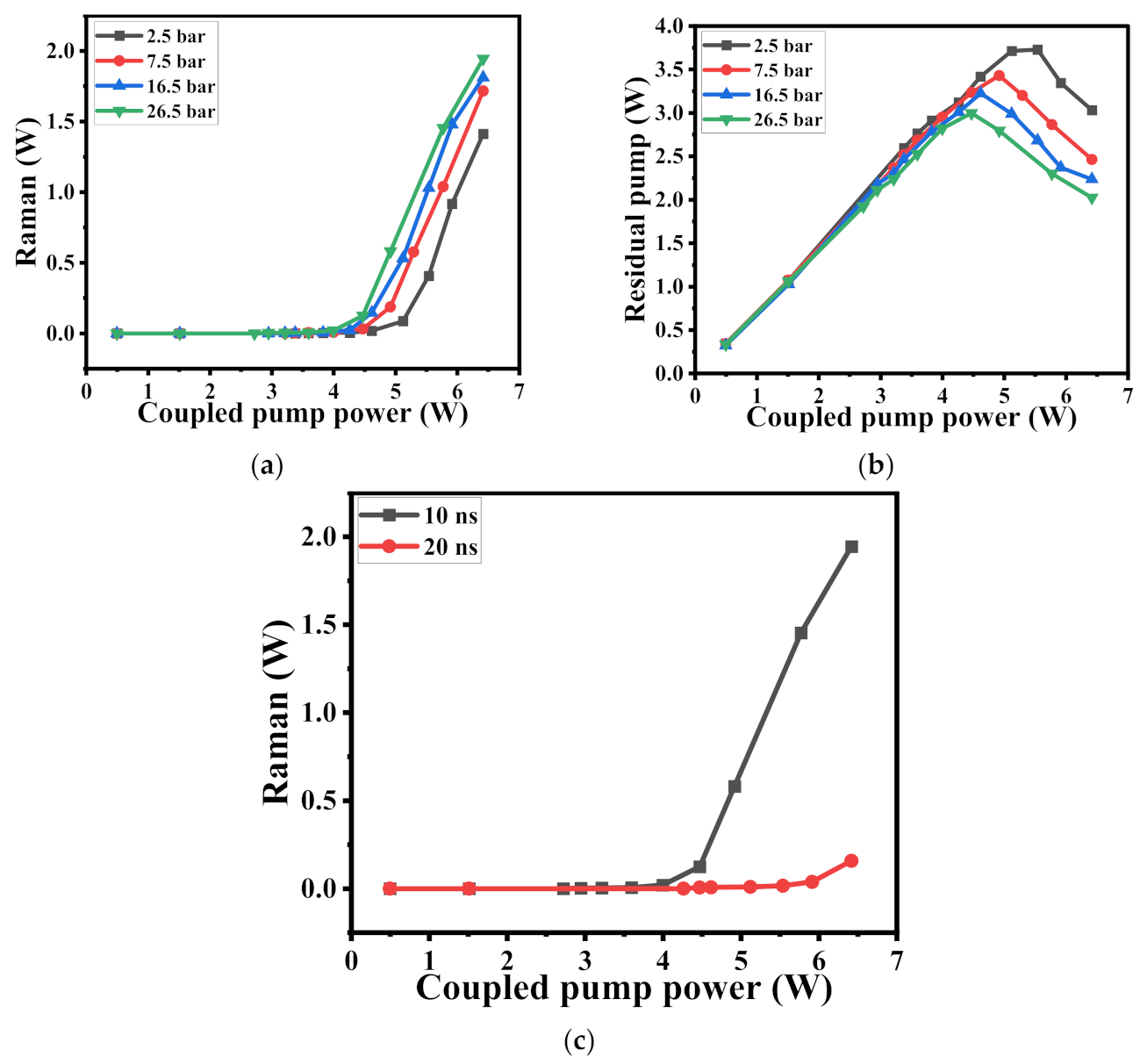
The correspondence between Raman power and pressure as well as the pulse width is also studied. When the fiber length is 12.8 m, by adjusting the deuterium pressure, we measured the Raman power and residual pump power as shown in Figure 7a,b. The Raman threshold drops clearly when the pressure increases, because the Raman gain coefficient is positively proportional to the gas pressure according to Equation (2), and the Raman power almost increases linearly after Raman conversion occurred. The maximum Raman power under this condition emerged at the pressure of 26.5 bar, and due to consideration of safety, the pressure is controlled to below 30 bar. Figure 7c shows the Raman power performance with different pulse widths. When the pulse width is set to 20 ns, there is few Raman power obtained, because the pumping peak power (inversely proportional to pulse width, Equation (1)) is too low due to the widened pulse width, only few part of the pump laser is converted.
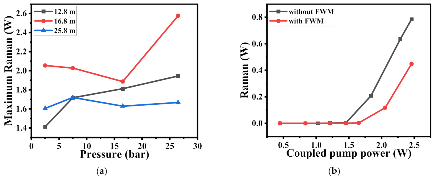
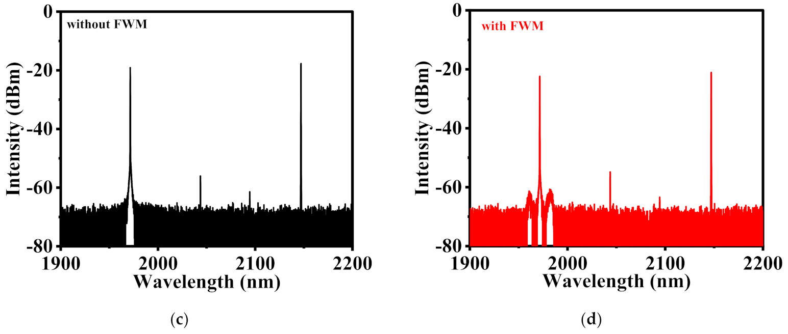
After we found the optimal deuterium pressure (26.5 bar), repetition frequency (1.5 MHz) and pulse width (10 ns) in our experiment, we studied the correspondence between the Raman power and fiber (HCF) length, and the results are displayed in Figure 8a. It can be seen that the optimal fiber (HCF) length in our experiment is 16.8 m, because if the fiber is too long, the Raman conversion is completed in a shorter distance and then come through a pure attenuating process; if the fiber is too short, the Raman threshold will increase, thus more energy is needed to exceed the threshold. Both of these two reasons would restrict the Raman power if the fiber is not of a proper length. However, it should be noted that the red and blue lines should have shared the same tendency with the black one: the Raman power is positively correlated to the pressure. We guess the instability (caused by the TDFA) of the spectrum accounts for it. Figure 8b shows the evolution of Raman power with and without four-wave mixing (FWM) of the 1971 nm pump laser. We can see that the Raman power apparently drops with FWM occurring. The spectrum of these two curves at the maximum Raman power is plotted in Figure 8c,d. According to Ref. [30], the FWM in our experiment is a degenerated four-wave-mixing (DFWM). Through careful investigation, we found the DFWM process occurred in the TDFA. Generally, the DFWM is impacted by the power of the center wavelength, fiber length and nonlinear coefficient [31]. However, in our experiment, the DFWM often occurs when the TFDA is turned on for beyond half one hour at the maximum pump power without changing any external conditions (e.g., fiber length), which means the internal conditions contributes to DFWM. Because the TDFA is a commercial one, we have no access to its internal configuration, thus we could not find the concrete reason which induces the DFWM. However, we guess when the TDFA is turned on under high pump power for a while, the accumulated heat would cause an increase of the pump pulse peak power, which decrease the threshold for DFWM. To prevent FWM from impacting the measuring process, we chose to turn off the TDFA every ~10 min.
This phenomenon has not been reported before, and we are still attending to explain why the spectrum of the pump laser can cause impacts on the Raman conversion efficiency. We have an assumption: the FWM in our experiment is a degenerated one, which means when a signal photon (generated in the TDFA) is amplified, there are two seed photons (emitted by the seed laser) consumed; when FWM occurs, the energy of the pump laser is dispersed (the intensity of the pump laser in Figure 8d is around 3 dB lower than that in Figure 8c), which means that DFWM caused a decrease of pump pulse energy, thus fewer part of pump laser is above threshold for Raman conversion, which finally contributes to an decrease of Raman power and conversion efficiency.

4. Conclusions

We demonstrate an efficient deuterium-filled fiber gas Raman laser working at 2.15 μm. The 2.15 μm Raman laser is obtained through pure rotational SRS of deuterium molecules. By adjusting the fiber (HCF) length, pressure, repetition frequency as well as the pulse width, a maximum average Raman power of 2.57 W is obtained, with a corresponding optical to optical conversion efficiency of 40%. By reducing the splice loss, the Raman power and conversion efficiency could be further enhanced. This work provides a simple and compact scheme for generating fiber lasers at 2.1 μm band, and is also of great significance for fiber gas Raman lasers.

Author Contributions

Conceptualization, Z.W. and Z.L.; methodology, Z.L.; software, W.H., H.L. and X.L.; validation, Z.W., W.P. and Z.L.; formal analysis, Z.W.; investigation, Z.L.; resources, Z.W.; data curation, Z.L.; writing—original draft preparation, Z.L.; writing—review and editing, Z.W.; visualization, Z.L.; supervision, Z.W.; project administration, Z.W.; funding acquisition, J.C. All authors have read and agreed to the published version of the manuscript.

Funding

This research was funded by National Natural Science Foundation of China (NSFC) (11974427, 12004431), State Key Laboratory of Pulsed Power Laser Technology (SKL2020ZR05, SKL2021ZR01) and Postgraduate Scientific Research Innovation Project of Hunan Province (CX20200004).

Institutional Review Board Statement

Not applicable.

Informed Consent Statement

Not applicable.

Data Availability Statement

The data presented in this study are available on request from the corresponding author. The data are not publicly available due to privacy.

Conflicts of Interest

The authors declare no conflict of interest.

References

  1. Lin, P.; Wang, T.; Ma, W.; Yang, Q.; Liu, Z. Transmission characteristics of 1.55 and 2.04 µm laser carriers in a simulated smoke channel based on an actively mode-locked fiber laser. Opt. Express 2020, 28, 39216. [Google Scholar] [CrossRef] [PubMed]
  2. Lahyani, J.; Le Gouët, J.; Gibert, F.; Cézard, N. 2.05-µm all-fiber laser source designed for CO2 and wind coherent lidar measurement. Appl. Opt. 2021, 60, C12–C19. [Google Scholar] [CrossRef] [PubMed]
  3. Wang, Q.; Geng, J.; Jiang, S. 2 μm fiber laser sources for sensing. Opt. Eng. 2013, 53, 061609. [Google Scholar] [CrossRef]
  4. Barnes, N.P.; De Young, R. Tm:germanate Fiber Laser for Planetary Water Vapor Atmospheric Profiling. In Proceedings of the Conference on Lasers and Electro-Optics/International Quantum Electronics Conference, Baltimore, MD, USA, 31 May 2009; p. JWA60. [Google Scholar]
  5. Yan, D.; Wang, Y.; Xu, D.; Liu, P.; Yan, C.; Shi, J.; Liu, H.; He, Y.; Tang, L.; Feng, J.; et al. High-average-power, high-repetition-rate tunable terahertz difference frequency generation with GaSe crystal pumped by 2 μm dual-wavelength intracavity KTP optical parametric oscillator. Photon. Res. 2017, 5, 82–87. [Google Scholar] [CrossRef] [Green Version]
  6. Holmen, L.G.; Fonnum, H. Holmium-doped fiber amplifier for pumping a ZnGeP2 optical parametric oscillator. Opt. Express 2021, 29, 8477–8489. [Google Scholar] [CrossRef] [PubMed]
  7. Yuan, J.-H.; Li, C.; Yao, B.-Q.; Yao, J.-Y.; Duan, X.-M.; Li, Y.-Y.; Wu, Y.-C.; Cui, Z.; Dai, T. High power, tunable mid-infrared BaGa4Se7 optical parametric oscillator pumped by a 2.1 μm Ho:YAG laser. Opt. Express 2016, 24, 6083. [Google Scholar] [CrossRef] [PubMed]
  8. Bloom, G.; Grisard, A.; Lallier, E.; Larat, C.; Carras, M.; Marcadet, X. Optical Parametric Amplification of a Distributed Feedback Quantum Cascade Laser in Orientation-Patterned GaAs. Opt. Lett. 2010, 35, 505–507. [Google Scholar] [CrossRef] [PubMed]
  9. Wood, C.; Carpenter, D.; Lyngnes, O. Laser Damage Testing for Ion Beam Sputtered Optical Coatings at 2um and 3um. Proc. SPIE-Int. Soc. Opt. Eng. 2011, 8039, 24. [Google Scholar] [CrossRef]
  10. Yao, W.; Shen, C.; Shao, Z.; Liu, Q.; Wang, H.; Zhao, Y.; Shen, D. High-power nanosecond pulse generation from an integrated Tm–Ho fiber MOPA over 2.1 μm. Opt. Express 2018, 26, 8841–8848. [Google Scholar] [CrossRef] [PubMed]
  11. Hollitt, S.; Simakov, N.; Hemming, A.; Haub, J.; Carter, A. A linearly polarised, pulsed Ho-doped fiber laser. Opt. Express 2012, 20, 16285–16290. [Google Scholar] [CrossRef]
  12. Wu, K.S.; Ottaway, D.; Munch, J.; Lancaster, D.G.; Bennetts, S.; Jackson, S.D. Gain-switched holmium-doped fibre laser. Opt. Express 2009, 17, 20872–20877. [Google Scholar] [CrossRef] [PubMed] [Green Version]
  13. Hemming, A.; Simakov, N.; Haub, J.; Carter, A. A review of recent progress in holmium-doped silica fibre sources. Opt. Fiber Technol. 2014, 20, 621–630. [Google Scholar] [CrossRef]
  14. Yan, P.; Sun, J.; Li, D.; Wang, X.; Huang, Y.; Gong, M.; Xiao, Q. 933 W Yb-doped fiber ASE amplifier with 50.4 nm bandwidth. Opt. Express 2016, 24, 19940–19948. [Google Scholar] [CrossRef] [PubMed]
  15. Russell, P.S.J.; Hölzer, P.; Chang, W.; Abdolvand, A.; Travers, J.C. Hollow-core photonic crystal fibres for gas-based nonlinear optics. Nat. Photonics 2014, 8, 278–286. [Google Scholar] [CrossRef]
  16. Benabid, F.; Knight, J.; Antonopoulos, G.; Russell, P. Stimulated Raman Scattering in Hydrogen-Filled Hollow-Core Photonic Crystal Fiber. Science 2002, 298, 399–402. [Google Scholar] [CrossRef]
  17. Wang, Y.; Schiess, O.T.S.; Amezcua-Correa, R.; Markos, C. CO2-based hollow-core fiber Raman laser with high-pulse energy at 1.95  µm. Opt. Lett. 2021, 46, 5133–5136. [Google Scholar] [CrossRef]
  18. Li, H.; Huang, W.; Pei, W.; Zhou, Z.; Cui, Y.; Wang, M.; Wang, Z. All-fiber gas Raman laser oscillator. Opt. Lett. 2021, 46, 5208–5211. [Google Scholar] [CrossRef]
  19. Li, H.; Huang, W.; Chui, Y.; Zhou, Z.; Wang, Z. Pure rotational stimulated Raman scattering in H2-filled hollow-core photonic crystal fibers. Opt. Express 2020, 28, 23881–23897. [Google Scholar] [CrossRef]
  20. Huang, W.; Li, Z.; Cui, Y.; Zhou, Z.; Wang, Z. Efficient, watt-level, tunable 1.7 μm fiber Raman laser in H2-filled hollow-core fibers. Opt. Lett. 2019, 45, 475–478. [Google Scholar] [CrossRef]
  21. Astapovich, M.; Gladyshev, A.; Khudyakov, M.; Kosolapov, A.; Likhachev, M.E.; Bufetov, I. Watt-level Nanosecond 4.42-μm Raman Laser Based on Silica Fiber. IEEE Photonics Technol. Lett. 2019, 31, 78–81. [Google Scholar] [CrossRef]
  22. Cao, L.; Gao, S.; Peng, Z.-G.; Wang, X.-C.; Wang, Y.; Wang, P. High peak power 2.8 μm Raman laser in a methane-filled negative-curvature fiber. Opt. Express 2018, 26, 5609. [Google Scholar] [CrossRef]
  23. Gladyshev, A.; Kosolapov, A.; Khudyakov, M.; Yatsenko, Y.; Kolyadin, A.; Krylov, A.; Pryamikov, A.; Biriukov, A.; Likhachev, M.E.; Bufetov, I.; et al. 4.4 μm Raman laser based on hollow-core silica fibre. Quantum Electron. 2017, 47, 491–494. [Google Scholar] [CrossRef]
  24. Chen, Y.; Wang, Z.; Li, Z.; Huang, W.; Xi, X.; Lu, Q. Ultra-efficient Raman amplifier in methane-filled hollow-core fiber operating at 1.5 μm. Opt. Express 2017, 25, 20944–20949. [Google Scholar] [CrossRef] [PubMed]
  25. Chen, Y.; Wang, Z.; Gu, B.; Yu, F.; Lu, Q. Achieving a 1.5 μm fiber gas Raman laser source with about 400 kW of peak power and a 6.3 GHz linewidth. Opt. Lett. 2016, 41, 5118–5121. [Google Scholar] [CrossRef]
  26. Wang, Z.; Yu, F.; Wadsworth, W.J.; Knight, J.C. Efficient 1.9 μm emission in H2-filled hollow core fiber by pure stimulated vibrational Raman scattering. Laser Phys. Lett. 2014, 11, 105807. [Google Scholar] [CrossRef] [Green Version]
  27. Benabid, F.; Bouwmans, G.; Knight, J.; Russell, P.; Couny, F. Ultrahigh Efficiency Laser Wavelength Conversion in a Gas-Filled Hollow Core Photonic Crystal Fiber by Pure Stimulated Rotational Raman Scattering in Molecular Hydrogen. Phys. Rev. Lett. 2004, 93, 123903. [Google Scholar] [CrossRef]
  28. Cui, Y.; Huang, W.; Li, Z.; Zhou, Z.; Wang, Z. High-efficiency laser wavelength conversion in deuterium-filled hollow-core photonic crystal fiber by rotational stimulated Raman scattering. Opt. Express 2019, 27, 30396–30404. [Google Scholar] [CrossRef]
  29. Li, Z.; Huang, W.; Cui, Y.; Wang, Z.; Wu, W. 0.83 W, single-pass, 1.54 μm gas Raman source generated in a CH4-filled hollow-core fiber operating at atmospheric pressure. Opt. Express 2018, 26, 12522–12529. [Google Scholar] [CrossRef]
  30. Aso, O.; Tadakuma, M.; Namiki, S. Four-Wave Mixing in Optical Fibers and Its Applications. Furukawa Rev. 2000, 1, 63–68. [Google Scholar]
  31. Agrawal, G. Chapter 10-Four-Wave Mixing. In Nonlinear Fiber Optics, 5th ed.; Agrawal, G., Ed.; Academic Press: Boston, MA, USA, 2013; pp. 397–456. [Google Scholar]
Figure 1. The experimental setup of the fiber gas Raman laser based on deuterium.
Photonics 09 00753 g001
Figure 2. (a) The spectrum of the seed laser; (b) the maximum output power of the TDFA at different repetition frequencies.
Photonics 09 00753 g002
Figure 3. (a) Scanning image of the cross section of HCF; (b) measured transmission loss of HCF.
Photonics 09 00753 g003
Figure 4. The output spectrum when the pump source (repetition frequency set to 1.5 MHz, pulse width set to 10 ns) is at a maximum output power (fiber length of 16.8 m, deuterium pressure of 26.5 bar).
Photonics 09 00753 g004
Figure 5. (a) The pulse train of pump laser; the pulse shape of (b) pump laser, (c) residual pump laser and (d) Raman laser.
Photonics 09 00753 g005
Figure 6. The evolution of (a) Raman power and (b) residual pump power with respect to the coupled pump power at different repetition frequencies (fiber length of 16.8 m, pressure of 26.5 bar).
Photonics 09 00753 g006
Figure 7. The evolution of (a) Raman power and (b) residual pump power with respect to the coupled pump power under different deuterium pressures; (c) the evolution of Raman power at different pumping pulse width (fiber length of 12.8 m, repetition frequency of 1.5 MHz).
Photonics 09 00753 g007
Figure 8. (a) Maximum Raman power under different fiber lengths and pressures; (b) Raman power with respect to the coupled pump power with & without FWM; the spectrum (c) without FWM & (d) with FWM.
Photonics 09 00753 g008aPhotonics 09 00753 g008b
Publisher’s Note: MDPI stays neutral with regard to jurisdictional claims in published maps and institutional affiliations.