Abstract
Recent studies have explored the synergy of illumination and positioning using indoor lighting infrastructure. While these studies mainly focused on the analysis of the performance of visible light positioning, these works did not consider the illumination aspects of such combined systems. In this paper, we analyse the illumination aspects based on the main illumination characteristics defined in the European Standard EN 12464-1, i.e., the horizontal illuminance and the uniformity of illuminance. As in the standard, we distinguish between a task area, where visual activities are performed that demand higher illuminance and uniformity, and a surrounding area that borders the former. In our analysis, we derive simple rules of thumb to determine the number and placement of LEDs to satisfy the constraints on the horizontal illuminance and uniformity for a given area.
1. Introduction
Visible light LEDs are progressively replacing traditional incandescent and fluorescent light sources, due to their energy efficiency and longer life time [1]. In contrast to the traditional light sources, LEDs can easily be modulated up to GHz, making them suitable for communication purposes. Furthermore, LEDs are typically mounted on the ceiling, implying most visible light communication (VLC) links contain a line-of-sight (LOS) component. Therefore, visible light LEDs are considered for indoor positioning. Several works have already investigated the accuracy of visible light positioning (VLP) systems [2,3,4], and reported excellent performance. They considered different approaches to estimating the position, i.e., based on the received signal strength (RSS) [5,6], angle-of-arrival (AOA) [7,8], time-of-arrival (TOA) [9,10] or based on the receiver type such as charge-coupled device (CCD) cameras or photo diode (PD) [11,12].
In the literature, it is stated that to have a low-cost solution, visible light communication and positioning can be combined with illumination after some minor adaptations in the infrastructure needed to modulate the LEDs. In those works, the synergy between positioning and illumination is seen from the positioning viewpoint, e.g., system parameters are optimised to achieve best positioning performance. In other words, the VLP system is prioritised over what is supposed to be the primary function of the illumination system, i.e., to provide adequate illumination to allow visual activities to be carried out safely. However, these studies make assumptions that could affect the level of visual comfort within the area where the system is evaluated, such as the placement of the LEDs on the ceiling, the optical power of the transmitters or the use of stand alone LEDs.
To the author’s best knowledge, only a few works deal with the optimisation of illumination, and these works mainly explore the process of designing and manufacturing light sources [13,14,15]. So, in order to offer design engineers simple guidelines for joint optimisation of illumination and positioning, we focus in this paper on the illumination aspects of a combined illumination and communication/positioning system. Taking as reference the EN 12464-1 standard, which stipulates and regulates all aspects to be considered for adequate lighting in indoor work areas, we analyse the horizontal illuminance and uniformity of illuminance in a given area. We scrutinise how parameters such as the number of LEDs (or LED arrays) and the spacing between them affect the illuminance of the room. In contrast to [16] where a metaheuristic planning algorithm is used, in which the placement of the LEDs is obtained through simulations, we provide in this paper simple analytical expressions for the optimal range of the number of LEDs and spacing between LEDs (or LED arrays) to comply with the requirements of the standard in terms of horizontal illuminance and uniformity. The resulting guidelines can be used in a broad range of situations, i.e., for rooms with different sizes, number of LEDs and Lambertian order of the LEDs.
2. System Description and Evaluation Criteria
In this paper, we assume L white LEDs are attached to the ceiling. We consider two scenarios: in the first scenario, we assume LEDs are grouped in arrays of LEDs, where and are the number of arrays in the x- and y-direction, respectively, and is the number of LEDs per array, so that , while in the second scenario, the L LEDs are stand alone, which corresponds to the special case where . Define as the set of LEDs within array , with , . Further, define the set of all L LEDs as . We assume that the centre of array ℓ has coordinates , Figure 1. The coordinates of LED within array ℓ are , where is the relative displacement of LED with respect to the centre of the array. We assume LED i within array ℓ has Lambertian order , which is connected to the semi-angle of the LED i at which half optical power is reached through . We assume the coordinates of all LEDs are known, and all LEDs point straight downwards, i.e., their normal is , , .
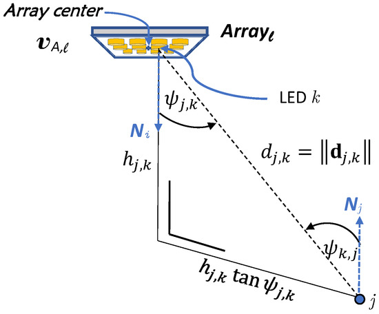
Figure 1.
Geometrical definitions in the illumination system, k corresponds to the pair .
Visual comfort, an important aspect to be considered especially for indoor environments, allows people to perform visual tasks efficiently and accurately. A lack or excess of light directly impacts this comfort. This comfort is measured through the illuminance level and its distribution in the area, where the illuminance, , is a function of the luminous intensity that measures the light intensity I emitted by a light source in a particular direction per unit solid angle [17], and is expressed by:
where is the spatial angle over which the luminous flux, , is distributed. For LEDs with Lambertian pattern, the radiation intensity, in [cd], of an LED in the direction is given by
where the centre luminous intensity equals , and m is the Lambertian order of the light source. We analyse the amount of light from LED with Lambertian order ; i.e., k corresponds to a pair , falling on a point j in a horizontal plane , with the vector between the LED k and point j equal to . The corresponding horizontal illuminance , in [lx], depends on the orientation of the light source with respect to the lit point j, i.e., the angle between the normal vector of the LED and , as well as on the orientation of the lit point j in the horizontal plane with respect to the LED k, i.e., the angle between the normal vector of the plane at point j and [18]. The horizontal illuminance is expressed by
with . In this paper, we assumed that the LED points straight downwards and the plane is parallel to the ceiling, implying .
In this paper, we evaluate the illumination requirements for indoor work areas. To this end, we consider the EN 12464-1 standard [19], which specifies the average illuminance as well as the uniformity of illumination, with the uniformity given by . Depending on the intended use of the areas, e.g., office, production and warehouse, the standard defines the lighting levels and distinguishes between task area and surrounding area. Table 1 shows the required illumination levels in the surrounding area for the given average illuminance in the task area. The uniformity of illumination also depends on the area type, and is constrained by for the task area, and for the surrounding area. For example, in an office area environment, the average illuminance must range between 300 and 500 lux.

Table 1.
Values of the illuminance and uniformity in the task and surrounding areas according to the standard EN 12464-1:2007 [19].
3. Analysis of Horizontal Illuminance and Uniformity
In this section, we analyse how parameters such as the number and position of LEDs affect the horizontal illumination and uniformity in the lighting system. We then outline some rules of thumb according to which LED arrays can be optimally installed to meet the requirements of adequate illumination. We consider that both the lit area that is evaluated and the ceiling area have dimensions with the latter located parallel and at a distance above the first. Without loss of generality, we set m, luminous flux and Lambertian order , , unless otherwise specified.
As the uniformity consists of the ratio of the minimum value and the average of the illuminance, we will first concentrate on the effect of the number and placement of the LEDs on and separately, and then extend the analysis to the uniformity. We first take a closer look at the average illuminance .
3.1. Average Horizontal Illuminance
Let us first consider the dependency of the average illuminance on the placement of the LEDs. To this end, we consider a square area where LEDs with lm are attached to the ceiling in a square grid with spacing between the LEDs. In Figure 2, we show the average illuminance , assuming m, and where is the maximum spacing for which all LEDs are within the area of interest. We only consider contributions from light radiated towards positions inside the considered area, and neglect reflection against walls and other objects. As can be observed, the average illuminance is relatively independent of the placement of the LEDs. For larger spacings , the average illuminance slowly decays, because LEDs will be placed closer to the edges of the considered area, implying more light is lost as it is radiated towards a position outside the area of interest. The reduction will be larger when more LEDs are close to the edges of the area of interest, i.e., when the number of LEDs is large and the area of interest is relatively small. While the effect of the placement of the LEDs on the average illuminance in most cases is limited, the figure reveals that the impact of the number of LEDs is much more important. Hence, in the following, we analyse the dependency of the average illuminance on the number of LEDs.
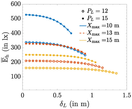
Figure 2.
Horizontal illuminance average for m, and lm.
Assume we measure the illuminance at a distance below the ceiling, where the LEDs are attached. The horizontal illuminance corresponding to a single LED, at a point at vertical distance below the LED and seeing the LED from an incident angle and azimuth angle is given by (3):
with being the luminous flux output of the LED. Using this expression, we now will formulate an upper and lower bound on the average illuminance in a rectangular area with size . We assume the LED is placed in the centre of this area. To find the upper bound, we compute the total illuminance in a circular area with radius . A straightforward choice for is , corresponding to the smallest circle that encloses the rectangular area with size . The resulting total illuminance within the circular area equals , where and
is the total illuminance in a circular area with radius R corresponding to a maximum radiation angle . As the circular area is larger than the rectangular area, this total illuminance is the upper bound to the total illuminance in the rectangular area. Dividing the total illuminance by the area of the rectangle therefore results in an upper bound on the average illuminance:
However, when the rectangular area is not close to a square area, this upper bound is far from tight. Therefore, we propose a tighter bound when the area is not close to a square. Assume . Let us consider the circle with radius . Although not all parts of the rectangular area are enclosed in this circle, the parts of the rectangle not contained in the circle lie at distance from the LED. At the same time, some parts of the circle will not be enclosed in the rectangle. In this latter case, the distance between a position in those parts and the LED is in the interval , with . Taking into account that the illuminance (4) reduces with the distance to the LED, it follows that the total illuminance in the circular area with radius is larger than that of the rectangular area, provided that the circular area is larger than the rectangular area, i.e., when . In this case, using to compute (6) yields a tighter upper bound as . In conclusion, the upper bound is given by (6), with where
In the derivation of (5), we assumed that the LED was positioned above the centre of the receiver area. This LED position maximises the amount of light inside the rectangular area . However, in practice, LEDs will be distributed over the area to achieve good uniformity of lighting. When an LED is not positioned in the centre of the rectangular area, the amount of light that falls outside the area will increase, implying (6) with computed using (7) can also serve as an upper bound for the total illumination within the rectangular area for other LED positions.
To find a lower bound on the average illumination, we consider the circular area with radius . Assuming the LED is placed in the centre of the rectangular area, this radius corresponds to the largest circle that is enclosed in the rectangular area. Hence, assuming the LED is placed in the centre, the resulting total illuminance within the circular area, i.e., (5) with , will be smaller than the total illuminance in the rectangular area as the parts of the rectangle that fall outside this circular area are neglected in the computation of the total illuminance. Further, to take into account that the total illuminance reduces when the LED is placed closer to the boundaries, we consider the worst case position for the LED. This worst case position is a corner of the rectangular area, resulting in a total illuminance , as 75% of the light is radiated to directions outside the rectangular area. While this illuminance is a strict lower bound on the total illuminance, it also strongly underestimates the true average illuminance in practical scenarios where LEDs are distributed over the area. To obtain a tighter bound, we therefore consider the situation where the LED is positioned at the boundary of the area, more specifically in the middle of the smallest side of the rectangle. In that case, only 50% of the radiated light is lost. Dividing the resulting total illuminance by the area , we obtain the following (approximate) lower bound on the average illuminance:
When L LEDs are placed in the area, the average illuminance will be bounded by:
Let us assume we want an average illuminance equal to lx, then we obtain the following bounds on the required number L of LEDs:
and
To illustrate, we consider a rectangular area with m, m and m, and LEDs with and lm. For an average illuminance lx, we obtain and for lx, .
Let us compare the resulting bounds on L with simulation results for the average illuminance. In this simulation, we placed LEDs in the rectangular area mentioned above. The L LEDs are attached separately to the ceiling in a rectangular grid of size , with , m and m, where the centre of the grid is the centre of the ceiling. The spacing between the LEDs equals and . The spatial average of the horizontal illuminance is shown in Figure 3 for different values of and , assuming lm. We observe that the required number of LEDs to achieve an average horizontal illuminance between 300 and 500 lx varies with , i.e., with the distribution of the LEDs over the ceiling. This is explained as LEDs near the boundaries will leak more light outside the receiver area than LEDs in the centre of the receiver area. Therefore, less LEDs will be needed to reach a given average illuminance when the LEDs are co-located in the centre, although it is clear that this will result in a worse uniformity than distributed LEDs. An average horizontal illuminance between 300 and 500 lx is obtained for , or . This falls within the interval predicted by the bounds on L, i.e., . Hence, the bounds (10) and (11) are suitable for obtaining an approximation for the number of required LEDs, where the lower bound is appropriate when the LEDs are all centered in the room, while the upper bound is more suitable when the LEDs are distributed over the whole receiver area.
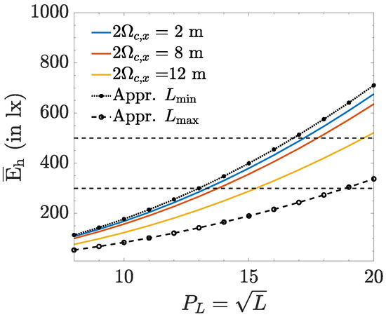
Figure 3.
Number of LEDs required to achieve , lm.
In our example, the number L of LEDs required to achieve an average illuminance in the interval lx was of the order 100–300. It is obvious that in practice, to reduce installation costs, these LEDs will not be attached individually to the ceiling. Instead, they will be grouped in luminaries containing several LEDs. In the following, we therefore assume that each luminary consists of an array of LEDs, resulting in arrays that need to be distributed over the ceiling, with . We assume that the arrays are placed in a rectangular grid with spacing and between the centers of the arrays. Within each array, we further assume that the spacing between the LEDs is small, so each luminary can be considered as a virtual LED with luminous flux .
3.2. Minimum Horizontal Illuminance
In the above analysis, we showed that the average illuminance imposes conditions on the required number of LEDs. In the following, we show that the optimal placement of the luminaries is determined by the uniformity of illumination, and more specifically by the minimum horizontal illuminance . Taking into account that the required uniformity differs for the task area and surrounding area, we first define the task area as the central area delimited by and , while the surrounding area is the strip at the edges of the receiver area, as illustrated in Figure 4.
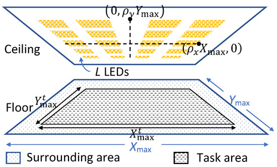
Figure 4.
Receiver area lit by L LEDs uniformly grouped in arrays on the ceiling within an area of .
First, we want to demonstrate that is essentially independent of the size of the area, and that it is mainly determined by the four parameters defined in Figure 5a, i.e., the distance and between the luminaries, and the distance and between the luminaries and the border of the area. To illustrate that, for given , the minimum is highly independent of the size of the area, we determine for different values of and with
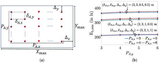
Figure 5.
(a) Receiver area layout of size with arrays and (b) for different , , , , and .
The resulting is shown in Figure 5b. As can be observed, the minimum of the horizontal illuminance is indeed essentially independent of and and thus of the size of the considered area, whereas it strongly depends on and, hence, the placement of the luminaries. Therefore, we will take a closer look at the impact of these four parameters on .
Because of the complexity of the expressions for the horizontal illuminance, i.e., the horizontal illuminance depends on a large number of parameters, a simple analytical expression for this minimum is not available, implying the minimum must be obtained through a two-dimensional search over the considered area. As such, a two-dimensional search comes with high complexity and gives no insight into the optimisation problem, in the following, we derive approximate expressions for the position of the minimum, with which we are able to obtain (an approximation of) the value of the minimum in an analytical way. Taking into account the dependency of the horizontal illuminance on the distance, it is clear that the minimum illuminance in an area is found in the part of the area surrounded by the least number of LEDs, so close to the corners of the considered (task or surrounding) area. Therefore, we restrict our attention to the evaluation area shown in Figure 6, which includes the four arrays closest to the boundary (indicated by the red dots). In the case of the surrounding area, the minimum is determined by the parameters . As all arrays are assumed to be inside the boundaries of the considered area, and are non-negative, and the relationship between and is given by (12), i.e., and . On the other hand, in the case of the task area, is determined by the parameters , where and can be negative if some of the arrays closest to the corner of the task area are located in the surrounding area. Assuming the task area has size with and , with , and and arrays are located inside the task area, it follows that
where the first lines in (13) correspond to the case that all LEDs in the x () and y directions (), respectively, are located in the task area, while in the second case, some of the LEDs are in the surrounding area. When (), the resulting () will be negative. Depending on the values of , the minimum illuminance will be in the corner of the considered area (see Figure 7a), close to the centre of the four arrays (see Figure 7b) or on the boundary of the considered area, close to the middle of the two nearest arrays (see Figure 7c), where the minimum can be on the boundary in the x direction () or in the y direction (), as defined in Figure 6. In our analysis, we will restrict our attention to these four positions, i.e., , , and . In the remainder of this section, we drop the superscript in and for notational simplicity.
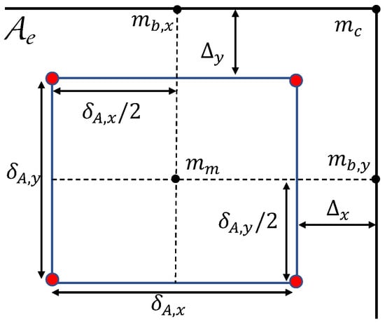
Figure 6.
Parameter definition for the evaluation area .

Figure 7.
Illumination patterns having the minimum (a) in the corner of the considered area, (b) close to the centre of the four arrays, (c) on the boundary of the considered area, approximately halfway between the two nearest arrays (here ).
To determine which of the four reference positions corresponds to the minimum for a given 4-tuple , we evaluate the horizontal illuminance at these points. The horizontal illuminance at a distance below an array and at a horizontal distance d from the array is equal to
where C is a factor that is independent of the distance d. As we want to compare illuminance levels at different positions in a horizontal plane at vertical distance from the array, we ignore in the following analysis the common factor C and use the function in the comparison. Combining the contributions from the four nearest arrays, we obtain the illuminance
where , are the distances between the reference point and the four considered arrays. These distances are given in Table 2 for the different reference points. To further simplify (15), we only consider the contributions from the nearest arrays, i.e., with the smallest :
where and is the number of terms in (15) corresponding to arrays at distance to the reference point. Using the resulting approximations (16), we will determine the reference point at which the horizontal illuminance is the smallest:
where . In the following, the subscript ’o’ is used to indicate the parameters corresponding to this optimal reference point. Note that when or , , and/or will fall outside the considered area, in which case we will omit the corresponding reference positions in our comparison. Taking into account (14), this comparison will result in inequalities of the form
with , and . From Table 2 and Equations (12) and (13), it follows that these inequalities give constraints on the spacing and between the arrays. More specifically, we can identify regions for each reference point in the plane, bounded by the conic sections following from the inequalities (18). This is illustrated in Figure 8a, in which we show the reference position that results in the minimum horizontal illuminance as a function of and , as well as the ellipses , , and , that form the decision regions between and with and , and the hyperbola that bounds the decision region between and . In Figure 8b,c, we show the true for the surrounding area and task area, respectively, and for m, m, m, , and , along with their delimiting conic sections. To find the true in the simulation, we used the true illuminance (14) and the contributions of all luminaries, where the minimum is found through an exhaustive search. As can be expected, the dependency of the minimum illuminance to the spacing between the luminaries is different for the two areas. For small , i.e., when the luminaries are tightly clustered in the centre of the ceiling, the corners of the area are poorly illuminated, resulting in a low in the surrounding area. At the same time, the centre of the area is better lit, implying in the task area is much higher. We observe in the figures that reaches a maximum value at some , but the position of the maximum is different for the task and the surrounding area. However, for both the task area and the surrounding area, the maximum is located on their respective hyperbolas, and , in the segment determined by the intersections between the ellipses and , and the ellipses and .

Table 2.
Distances between the arrays and the reference points.

Figure 8.
For m, m, m, , and (a) shows the decision regions for in the plane to obtain the minimum horizontal illuminance in both (b) the surrounding area and (c) the task area.
3.3. Uniformity
Using the analysis of Section 3.1, we are able to determine the range for the total number L of LEDs required to satisfy the constraints on the average horizontal illuminance. The next step is to determine how these LEDs must be grouped in luminaries, i.e., arrays of LEDs, to satisfy the uniformity constraints. It is obvious that when the number of luminaries is large, the uniformity constraints will be satisfied, although this will come with a large installation cost. Hence, we are interested in finding (1) the minimum number of luminaries for which in both areas the uniformity is larger than the threshold , , and (2) the range over which the spacing may vary for a given number of luminaries. In the following, we define as the ratio between the dimensions of the area, and as the ratio of the number of arrays in each dimension.
In Figure 9, we show the uniformity as a function of the spacing for both the task and surrounding area, for m, , , , and m. The uniformity is computed using (14) and takes into account the contributions from all luminaries, where to obtain , we use the estimated position (17) of the minimum. We also show in both figures the region in which the uniformity exceeds the respective thresholds, i.e., (bounded by the red curve) for the task area, and (bounded by the green curve) for the surrounding area, as well as the compliance region (bounded by the dotted curve), which is the region for where the uniformity constraints in both the task and surrounding area are satisfied: . This compliance region changes when we alter one or more of the following parameters: the area size , the number of arrays , the Lambertian order or the vertical distance . In some cases, the compliance region will be empty, e.g., if the number of arrays is not sufficiently large to meet the uniformity constraints irrespective of the spacing between the arrays. In general, if the number of arrays is sufficiently large, the compliance region will result in a relatively large range of potential spacings . Unfortunately, due to the complexity of the problem, no analytical expression for the boundaries of this compliance region can be derived.
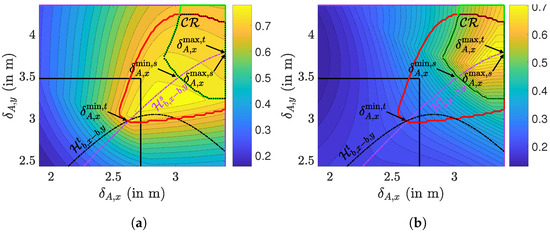
Figure 9.
Uniformity distribution for m, , , m and . (a) and (b) .
We will therefore approach the problem from a slightly different viewpoint. Let us consider the maximum uniformity in the task and the surrounding area. Firstly, this maximum will give an indication if the compliance region is empty. Indeed, if the maximum value of the uniformity is below the threshold in the task or surrounding area, the compliance region will be empty. However, even if for both the task area and surrounding area the maximum is above the threshold, it is not guaranteed that the compliance region is non-empty, i.e., if the regions for the task area and surrounding area do not overlap. Secondly, for a given number of luminaries, the maximum uniformity will result in the highest comfort to the user. Therefore, we look for the values of where for given , the corresponding value for results in the largest uniformity, i.e., the ridge in the uniformity distribution. As we can observe in the figure, the ridge of maximum values of the uniformity for a given in the surrounding area approximately corresponds to the hyperbola . This is obvious, as in the previous section, the maximum value of for given was shown to be on this hyperbola, and the average horizontal illuminance is largely independent of the array spacing. For the task area, the ridge of maxima of will fall on the hyperbola provided that no luminaries are located outside the task area. However, when for this maximum some luminaries are outside the task area, the hyperbola no longer follows the ridge of maxima. Regardless of the placement of the luminaries, we observed in our simulations that the hyperbola of the surrounding area roughly follows the ridge of maxima in the task area. Therefore, we will consider for both areas the hyperbola to determine the value of corresponding to the maximum uniformity for a given .
To obtain the range of and corresponding for which the uniformity constraints are satisfied, we determine the intersections between the hyperbola and the regions where the uniformity is above the threshold in the task and surrounding area, respectively, i.e., for the task area, when the point on the hyperbola satisfies and for the surrounding area when the point on the hyperbola satisfies , as indicated in Figure 9. The range for where the uniformity constraints are satisfied for both regions, i.e., where the spacing belongs to the compliance region, is then given by the intersection of the two intervals: , where and . As can be observed in the figure, the upper bound may coincide with the maximum possible spacing , or in some situations with . Let us therefore first compute the points and on the hyperbola corresponding to the maximum spacing and . After some straightforward derivations, it follows that if , and that if . Hence, when , the hyperbola will first cross the maximum , implying this is the tightest maximum spacing, while when , then the hyperbola first crosses the maximum , which then is the tightest maximum spacing. Hence, the following upper bound on can be formulated:
with
Taking into account that , it follows that both bounds in (19) are linear in .
Next, we determine the other bounds for for given parameter settings, i.e., for different , , , , , , and . To this end, let us compute the true uniformity and , i.e., without use of any approximations, and determine the bounds using an exhaustive search. In Figure 10, we show the resulting range of , i.e., the green areas, as a function of the size of the area for different values of , and , for m and . As can be observed in the figure, the bounds and depend in a piece-wise linear way on the size of the area. This piece-wise linear behaviour could be expected, as to keep an as large as possible uniformity, scaling the area while keeping the number of luminaries equal will result in a scaling of the spacing between the luminaries, resulting in a linear behaviour. The piece-wise character of the bounds is because at some point the lower (upper) bound corresponding to the task area becomes tighter than that of the surrounding area, or vice versa. Therefore, we approximate the range for as a function of as a piece-wise linear upper and lower bound, as shown in Figure 11. The first bound is (19), due to the maximum allowed spacing to keep all luminaries within the considered area. The spacing serves as an upper bound on the spacing for the task area as well as for the surrounding area in case the uniformity constraints still hold for this maximum possible spacing, which occurs when the considered area is sufficiently small. When the area size is larger, the uniformity constraints no longer will be met for the maximum possible spacing . In that case, the upper bound on will be determined by . In our simulations, we always found that , implying we can ignore the bound . To find the expressions for the linear equations for , and , we carried out a large number of simulations for various values for the parameters , , , and , and matched the coefficients of the linear equations to the simulated bounds. This resulted in the empirical equations
where , and follows from the definition of the size of the task area. The resulting bounds are shown in Figure 10. As can be observed, the bounds match well the true bounds on for given area size. The bounds were tested for the parameter ranges given in Table 3, and were found to be accurate. Hence, the empirical bounds (21) can be used for at least these parameter settings. Taking into account that it is required that , it follows that . This yields the following lower bound on the number of luminaries:
and consequently
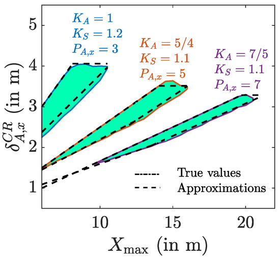
Figure 10.
Boundary intervals for the spacing in the compliance region for different , and with , m and .
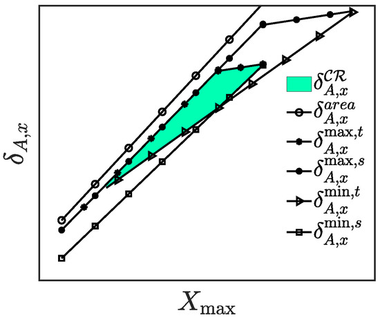
Figure 11.
Linearised bounds on .
To verify the resulting bounds on , let us consider the same example we used to determine the range for the number of LEDs to achieve an average illuminance in the range [300,500] lx, i.e., with m, m, , lm and (i.e., ). By using (10) and (11), we determined that the number L of LEDs needed to have an average horizontal illumination between 300 and 500 lux ranges in . In the following, we assume . These LEDs must be grouped in luminaries, in a grid of luminaries. In our example, we assume , i.e., . Further, the dimensions of the task area are selected as with and . For the task area, we assume the threshold for uniformity is and for the surrounding area . This yields . Applying the bounds (22) and (23), it follows that the number of luminaries is lower bounded by and . This gives LEDs per luminary. As , it follows that the bound (19) is determined by the maximum spacing . This yields m. On the other hand, m, implying m. Similarly, we compute the lower bounds using Equation (21) to obtain m and m, and thus m. This results in the interval m.
To check if this interval corresponds to the true compliance region for the given parameter values, we computed the true uniformity and average illuminance. The uniformity for the task and surrounding area are shown in Figure 12a, and the average horizontal illuminance for the task area , surrounding area and the whole area of interest in Figure 12b. In the figure, we show the true compliance interval in which the uniformity in both the task and surrounding area are above the threshold. As can be observed, the predicted compliance region is contained in the true compliance region , , although the predicted interval slightly underestimates the true interval. We noticed in our simulations that when the difference , the predicted interval tends to underestimate the interval, although the predicted interval still results in a system setup that satisfies the constraints on the illuminance level and uniformity. In Figure 13, the compliance intervals are shown for different values for , for . As can be observed, the predicted and the true compliance interval match very well for . As in practice, the number of luminaries is scaled with the dimensions of the area, i.e., , this implies the proposed approximations predict the range of potential spacings between the luminaries well.
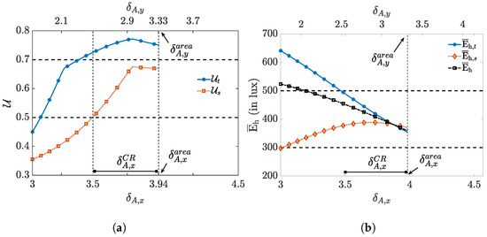
Figure 12.
True values of (a) uniformity: and , and (b) the horizontal illuminance average: , and , for m, , m, , lm, , , LEDs, and .
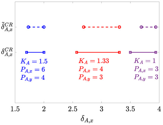
Figure 13.
True range of versus predicted range , for m, , m, lm, , , LEDs and for different .
4. Conclusions
In this paper, we considered the illumination for indoor areas, in the context of a combined illumination and positioning or communication system. To this end, we analysed the effect of the number and placement of LEDs on the main illumination characteristics, i.e., the average horizontal illuminance and uniformity, as defined in the DIN EN 12464-1 standard. We summarise our main contributions:
- The average horizontal illuminance is largely independent of the placement of the LEDs, but depends strongly on the number of LEDs. On the other hand, the uniformity mainly depends on the placement of the LEDs.
- The minimum of the horizontal illuminance is crucial to determine the uniformity. To avoid a two-dimensional search for the minimum value, we analysed the position of the minimum. We found that the minimum value can be found at one out of four positions, as illustrated in Figure 7. To determine which of these four positions correspond to the minimum, we need to evaluate the conic sections given by Equation (18), resulting in the decision regions depicted in Figure 8a. This position of the minimum allows us to easily compute the minimum of the horizontal illuminance, and thus the uniformity.
- To determine for a given number of luminaries the spacings for which the illumination constraints are satisfied, we proposed the bounds Equations (19) and (21). These bounds provide a range for the spacing between luminaries, from which we can find an expression for the minimum number of luminaries (Equation (22)) required to meet the illumination constraints.
- The resulting rules of thumb were tested for a wide variety of system parameters, as illustrated in Table 3.
These guidelines will help a design engineer to construct a combined illumination and positioning or communication system that meets the illumination standard.
Author Contributions
Research, J.M.M.; Writing, J.M.M.; Editing, H.S.; Supervising, H.S.; Funding, H.S. All authors have read and agreed to the published version of the manuscript.
Funding
José Miguel Menéndez acknowledges the National Secretariat of Higher Education, Science, Technology and Innovation of Ecuador (SENESCYT) for their financial support. This work is partially funded by the EOS grant 30452698 from the Belgian Research Councils FWO and FNRS. Further, it is funded by the Flemish Government (AI Research Program).
Institutional Review Board Statement
Not applicable.
Informed Consent Statement
Not applicable.
Data Availability Statement
Not applicable.
Conflicts of Interest
The authors declare no conflict of interest.
References
- Cheng, Y.-K.; Cheng, K.W.E. General study for using LED to replace traditional lighting devices. In Proceedings of the 2006 2nd International Conference on Power Electronics Systems and Applications, Hong Kong, China, 12–14 November 2006; pp. 173–177. [Google Scholar]
- Hou, Y.; Xiao, S.; Bi, M.; Xue, Y.; Pan, W.; Hu, W. Single LED beacon-based 3-D indoor positioning using off-the-shelf devices. IEEE Photonics J. 2016, 8, 1–11. [Google Scholar] [CrossRef]
- Wang, T.Q.; Sekercioglu, Y.A.; Neild, A.; Armstrong, J. Position accuracy of time-of-arrival based ranging using visible light with application in indoor localization systems. J. Light. Technol. 2013, 31, 3302–3308. [Google Scholar] [CrossRef]
- Yang, S.H.; Jeong, E.M.; Kim, D.R.; Kim, H.S.; Son, Y.H.; Han, S.K. Indoor three-dimensional location estimation based on LED visible light communication. Electron. Lett. 2013, 49, 54–56. [Google Scholar] [CrossRef]
- Menendez, J.; Steendam, H. Influence of the aperture-based receiver orientation on RSS-based VLP performance. In Proceedings of the 2017 International Conference on Indoor Positioning and Indoor Navigation, Sapporo, Japan, 18–21 September 2017. [Google Scholar]
- Stevens, N.; Steendam, H. Influence of transmitter and receiver orientation on the channel gain for RSS Ranging-based VLP. In Proceedings of the 2018 11th International Symposium on Communication Systems, Networks & Digital Signal Processing (CSNDSP’18), Budapest, Hungary, 18–20 July 2018. [Google Scholar]
- Cincotta, S.; He, C.; Neild, A.; Armstrong, J. High angular resolution visible light positioning using a quadrant photodiode angular diversity aperture receiver (QADA). Opt. Express 2018, 26, 9230–9242. [Google Scholar] [CrossRef] [PubMed]
- Sahin, A.; Eroglu, Y.S.; Guvenc, I.; Pala, N.; Yuksel, M. Accuracy of AOA-based and RSS-based 3D localization for visible light communications. In Proceedings of the V2015 IEEE 82nd Vehicular Technology Conference (VTC2015-Fall), Boston, MA, USA, 6–9 September 2015; pp. 1–5. [Google Scholar]
- Jung, S.-Y.; Hann, S.; Park, C.-S. TDOA-based optical wireless indoor localization using LED ceiling lamps. IEEE Trans. Consum. Electron. 2011, 57, 1592–1597. [Google Scholar] [CrossRef]
- Nadeem, U.; Hassan, N.U.; Pasha, M.A.; Yuen, C. Highly accurate 3D wireless indoor positioning system using white LED lights. Electron. Lett. 2014, 50, 828–830. [Google Scholar] [CrossRef]
- Hijikata, S.; Terabayashi, K.; Umeda, K. A simple indoor self-localization system using infrared LEDs. In Proceedings of the 2009 Sixth International Conference on Networked Sensing Systems (INSS), Pittsburgh, PA, USA, 17–19 June 2009; pp. 1–7. [Google Scholar]
- Steendam, H.; Wang, T.; Armstrong, J. Theoretical lower bound on VLC-based indoor positioning using received signal strength measurements and an aperture-based receiver. J. Light. Technol. 2017, in press. [Google Scholar] [CrossRef]
- Cassarly, W.; Hayford, M. Illumination optimization: The revolution has begun. Int. Opt. Des. Conf. 2002, 4832, 258–269. [Google Scholar]
- Davenport, T.; Hough, T.; Cassarly, W. Optimization for illumination systems: The next level of design. Photon Manag. 2004, 5456, 81–90. [Google Scholar]
- Jacobson, B.; Gengelbach, R. Lens for uniform LED illumination: An example of automated optimization using Monte Carlo ray-tracing of an LED source. Nonimaging Opt. Maximum Effic. Light Transf. VI 2001, 4446, 121–128. [Google Scholar]
- Bastiaens, S. Towards Centimetre-Order Indoor Localisation with RSS-Based Visible Light Positioning. Ph.D. Thesis, University of Ghent, Ghent, Belgium, 2022. [Google Scholar]
- Ghassemlooy, Z.; Popoola, W.; Rajbhandari, S. Optical Wireless Communications: System and Channel Modellin with Matlab®; CRC Press: Boca Raton, FL, USA, 2012. [Google Scholar]
- Komine, T.; Nakagawa, M. Fundamental analysis for visible-light communication system using LED lights. IEEE Trans. Consum. Electron. 2004, 50, 100–107. [Google Scholar] [CrossRef]
- Normung, D. Light and Lighting–Lighting of Work Places–Part 1: Indoor Work Places; DIN EN 12464-1; DIN: Berlin, Germany, 2011. [Google Scholar]
Publisher’s Note: MDPI stays neutral with regard to jurisdictional claims in published maps and institutional affiliations. |
© 2022 by the authors. Licensee MDPI, Basel, Switzerland. This article is an open access article distributed under the terms and conditions of the Creative Commons Attribution (CC BY) license (https://creativecommons.org/licenses/by/4.0/).