Article

Design of a Fiber Alkali Vapor Cell for Atomic Magnetometer for Magnetoencephalography Applications

1
Key Laboratory of Optical Technology and Instrument for Medicine, Ministry of Education, School of Optical-Electrical and Computer Engineering, University of Shanghai for Science and Technology, Shanghai 200093, China
2
Department of Physics, King’s College London, London WC2R 2LS, UK
3
School of Optical-Electrical and Computer Engineering, University of Shanghai for Science and Technology, Shanghai 200093, China
4
Shanghai Institute of Intelligent Science and Technology, Tongji University, Shanghai 200093, China
*
Author to whom correspondence should be addressed.
Photonics 2022, 9(10), 749; https://doi.org/10.3390/photonics9100749
Submission received: 21 August 2022 / Revised: 3 October 2022 / Accepted: 6 October 2022 / Published: 10 October 2022

Abstract

:
Spin exchange relaxation free (SERF) atomic magnetometer (AM), based on the Larmor precession of alkali atoms, is considered a promising candidate for magnetoencephalography (MEG) systems with the advantages of high sensitivity and no need for cryogenic devices. The footprint of the sensor header contains alkali vapor cell and bulk optical elements determining the spatial resolution of the MEG system. Optical fiber could separate the vapor cell far from other parts of the sensor header to improve the spatial resolution. However, coupling between glass cell and fibers limits the coupling loss of the light. Here, we describe the design of a fiber-based alkali vapor cell that could alleviate these issues. A pair of fiber cables combining a polarization maintaining fiber (PMF) and hollow-core photonic crystal fibers (HC-PCFs) are enclosed in a vacuum-sealed T-shape glass tube filled with alkali atoms. The fiber cell ensures a flexible integration with most fiber systems. The fiber structure, with an air gap between HC-PCFs, provides a large interaction volume between light and atoms. The vapor of the alkali atoms diffuses into the air core of the HC-PCF from the glass tube by heating. The alkali atoms still contained in SERF regime are within the wall relaxation rates of 12,764 s−1 in the coating fiber cell. The insertion loss due to fiber coupling is analyzed. The coupling efficiency could be 91%, with the fiber structure consisting of a 40 μm diameter HC-PCF and a 1 mm air gap. The limit sensitivity under this condition is simulated at 14.7 fT/Hz1/2. The fabrication technique and the light insertion loss are discussed. The fiber alkali vapor cell is of compact size and has flexible integration with the fiber atomic spin precession detection system.

1. Introduction

Ultra-high-sensitivity magnetometry can sense magnetic signals from neuronal activity in the brain [1]. Hundreds of magnetometers detect anomaly magnetic signals to locate sources of cerebral diseases for magnetoencephalography (MEG) [2]. Compact magnetometers with a small cross-section improve the spatial resolutions of MEG at the millimeter level [3]. Compared with Superconducting Quantum Interference Device (SQUID) magnetometer [4], the atomic magnetometer has a simpler structure, as no cooling equipment is required in the system. Atomic magnetometer with a spin exchange relaxation free (SERF) regime achieved the record of weak magnetic field measurement of 0.16 fT/Hz1/2, and becomes a candidate for application to MEG [5]. Fiber-coupled AMs improve the resolution by separating the controllers from the sensor headers [6]. However, the bulk optical elements and glass vapor cell at the millimeter level limit the spatial resolution [7,8,9]. The microfabricated AM has a spatial resolution of 1 cm2 with a sensitivity of 20 fT/Hz1/2 [10]. The commercial AM has a footprint of 13 × 19 mm2, with a sensitivity of 10 fT/Hz1/2 [11]. In 2019, the fiber Sagnac interferometer detected atomic spin precession in SERF AM [12], which could further remove the vapor cell from the fiber optical path. The alkali atoms could be filled into the hollow core photonic crystal fiber (HC-PCF) with a micrometer cross-section [13]. Fiber cells would be an ideal sensor header, with better compatibility in the fiber system. Thus, the study of the fiber cell is significant to improve the spatial resolution of the AM. At present, the research into fiber alkali vapor cell, particularly when used for SERF atomic magnetometer, has not been reported, except for applications in absorption spectroscopy [14], integrated atomic frequency standard [15], Rydberg state spectroscopy [16], cold atom experiments and quantum optics applications [17]. Different from SERF AM, a high density and vacuum are required, but the low relaxation rates are not considered in those applications. In 2008, Slepkov’s group at Cornell University designed a fiber atomic vapor cell with a vacuum-sealed system [18]. The system consisted of a 4.5 cm long HC-PCF with a core diameter of 6 μm, which was connected to an ampoule containing Rb atoms. Using the light-induced atomic desorption (LIAD) technique, atoms were filled into the fiber core, which also contained probe and desorption beams in a counter-propagating geometry. However, the fiber cell limited the light efficiency of fiber coupling. In 2015, Oxford University punched Cs atoms into 26 μm and 46 μm diameter, kagomé-style HC-PCFs [19]. The optical depth OD = 2000 was achieved in the fiber cell that existed for a few hours [20]. In 2017, Low’s team at the University of Stuttgart spliced two conventional optical fibers to each end of a capillary. This was mainly realized through a decentered splice technique, allowing for the capillary to be refilled from the reservoir containing alkali atoms [21]. The atomic absorption spectra of the transmission light were successfully measured, but optical loss was too high for SERF applications. However, multimode fibers cannot maintain the polarization information, which does not meet the requirements of atomic spin precession detection [22].
In this paper, the design of a fiber alkali vapor cell was proposed for application to SERF AM. The structure and characteristics are described. The optimization of fiber diameter with low relaxation and the high light coupling efficiency are discussed. The fiber cell has potential to improve the resolution of the SERF atomic magnetometer. Moreover, the relaxation of wall collision and limit sensitivity are analyzed. The method to mitigate wall relaxation is discussed.

2. Theory Model and Fabrication of Fiber Atomic Vapor

The basic principle of AM is based on Larmor precession. Atomic spin generates precession around the magnetic field at an angular frequency of Ω = γ B /q, where γ is the gyomagnetic ratio, B is the magnetic field, h is plank constant, g is the Lande-g factor, and q is the nuclear slow-down factor. The atoms are polarized by the circularly polarized light resonant to the atoms. The spin polarization can be monitored by linearly polarized light, as the absorptive and dispersive properties of vapor cell are modulated by spin precession [6].
Generally, the limit sensitivity of the atomic magnetometer depends on the relaxation rates and the interaction volume between light and atoms [23], which is:
δ B = 1 γ n T 2 V t
where n = 10 26.268 4453 / T / T is the number density of atoms, γ is the gyromagnetic ratio, V is the measurement volume, and t is the measurement time. T 2 = 1 / R t o t a l is the transverse spin relaxation time, R t o t a l is the total relaxation rate, containing relaxations of spin destruction, wall and spin exchange:
R t o t = 1 q R S D + R p + R w + 1 q S E R S E
where R S D is the spin relaxation due to atomic spin destruction collisions, R p is the pump rate of the interaction between pump light and atoms, q is the nuclear slowing down factor, q S E is the broadening factor depending on the ambient magnetic field, R S E is the rate of spin-exchange collisions between alkali atoms, R w is the wall relaxation depending on the size of fiber core a and diffusion coefficient of the atoms D.
Different from Stuttgart University [21], the structure of the fiber cell is symmetrical, with a pair of fiber cables sealed to each side of a T-shape glass tube, as shown in Figure 1. The glass tube is filled with alkali atoms. The fiber cable is a polarization-maintaining fiber (PMF) spliced with the HC-PCF. The fast and slow axes of the PMF have different refractive indices related to their birefringence. If the linearly polarized light enters the PMF at 45° to the fast axis, it will be divided into orthogonal components along each axis of the PMF with different phase delays. The circularly polarized light could be generated by the PMF, as the phase difference between axes could be modulated by birefringence and fiber length. Thus, the PMF could be available for pumping and probing alkali atoms. To achieve better sensitivity, the interaction between light and atoms should be considered according to Equation (1). The core diameter of the HC-PCF could be larger than 50 μm; the sensing volume could be adjusted by the length of the HC-PCF. Two 2.5 cm long HC-PCFs are aligned with an air gap opening, providing access for alkali atoms diffusing into the HC-PCF. The volumes of the air core of the HC-PCFs and the air gap form the sensing volume of the AM. Each fiber cable is plunged into a ceramic ferrule, which is fixed in the ceramic sleeve to generate an air gap of 2–4 mm.
The fiber cables are sealed with the glass tube using vacuum screw caps. The sealing pipes with external thread are installed at both ends of glass tube through the mechanical structure. Keeping the optical fiber in the glass tube naturally straightened, the connection between the optical fiber and the sealing cap is sealed with vacuum sealant. Vacuum sealant should be completely dried after the subsequent operation.
The T-shape glass tube is filled with materials, including alkali metal, inert and quenching gases, which meet different demands of the atomic magnetometer. The filling process is achieved through the short port of the T-shape glass tube. After filling, the short port is sintered and sealed to ensure that the material in the tube will not leak. The spatial resolution of the designed vapor cell is determined by the cross-section of the sealing pipes. If the HC-PCF could be filled with atoms and individually sealed, spatial resolution would be determined by the cross-section of the fiber at micrometer level.

3. The Characteristics of Fiber Cell

3.1. Relaxation of the Fiber Cell

The small interaction volume of the fiber cell decreases the limit sensitivity. By using HC-PCF, atoms can be filled into the hollow core to realize a larger interaction volume with the light. At present, the core diameter of the HC-PCF can reach tens of microns, which is still at least three orders of magnitude smaller than the 0.77 mm3 vapor cell of the current MEMS-miniaturized AM [24]. In the small cell, atoms will quickly collide with the cell wall and lose coherence, which generates a large level of wall relaxation. For convenience, it is assumed that the fiber core is composed of numerous small spatial units in sequence. Each unit acts independently to generate the wall relaxation, which is:
R w = 1 T w a l l = D π a 2
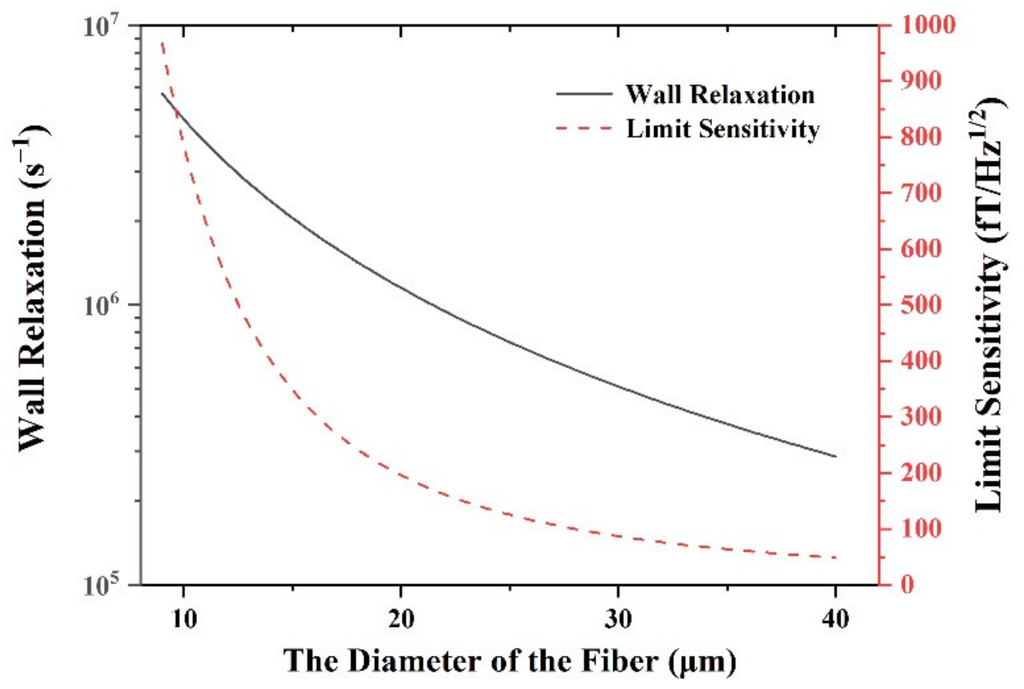
where T w a l l is the relaxation time for wall collision of the atoms, D is the diffusion constant depending on alkali species [25]. It is assumed that the filled atoms are potassium, the buffer gas is He, and the diffusion constant is 0.11 cm/s (3 amg He @ 180 °C). The density of the atoms is 6.05 × 1013 cm−3; the measurement time is 1 s. The wall relaxation in the HC-PCF and the limit sensitivity for SERF AM changes with the fiber core diameter, as shown in Figure 2.
The black solid line indicates the wall relaxation of the fiber cell. The wall relaxation rates decrease rapidly from 5.69 × 10⁶ s−1 to 2.88 × 10⁵ s−1 with the increase in fiber core diameter from 4.5 μm to 40 μm. The red line in Figure 2 shows that the limit sensitivity for SERF AM increases from 967 fT/Hz1/2 to 48.2 fT/Hz1/2, corresponding to the wall relaxation rates. Compared with the relaxation rates of other regimes, the wall relaxation is the major one, which determines the limit sensitivity of the AM according to Equation (1).

3.2. Light Loss of the Fiber Cell

The coupling efficiency of optical fibers determines the power consumption of the fiber cell. The atomic spin precession signal is directly proportional to the light intensity. The precession signal responding to the MEG is weak and sensitive to low-frequency noise. Many factors, such as light intensity fluctuations, environmental vibrations and temperature fluctuations, will generate noise to drown the signal. To solve this problem, The fiber cables are inserted and sealed into the T-shape glass vapor cell. In addition, the conventional vapor cell is transparent on each side. If the scheme of the fiber cell is adopted, the light can only be transmitted through the input fiber; then, it passes through the air gap and needs to be coupled to the output optical fiber to ensure the normal operation of the subsequent fiber optical path. Thus, the coupling efficiency from the air gap to the output fiber is simulated for the fiber cell. The model of the fiber cell is shown in Figure 1. The main light loss is in the air gap due to the fiber coupling. The conventional fiber coupling system is shown in Figure 3.
In the space optical path, a beam of collimating light with radius ω 1 enters the optical fiber with core diameter ω 0 . The efficiency of fiber coupling is described as
η = κ exp κ x 0 2 2 1 / ω 1 2 + 1 / ω 0 2
κ = 4 ω 1 2 ω 0 2 / ω 1 2 + ω 0 2 2 + λ 2 z 2 / π 2
ω 1 2 z = ω 1 2 1 + λ z / π ω 1 2 2
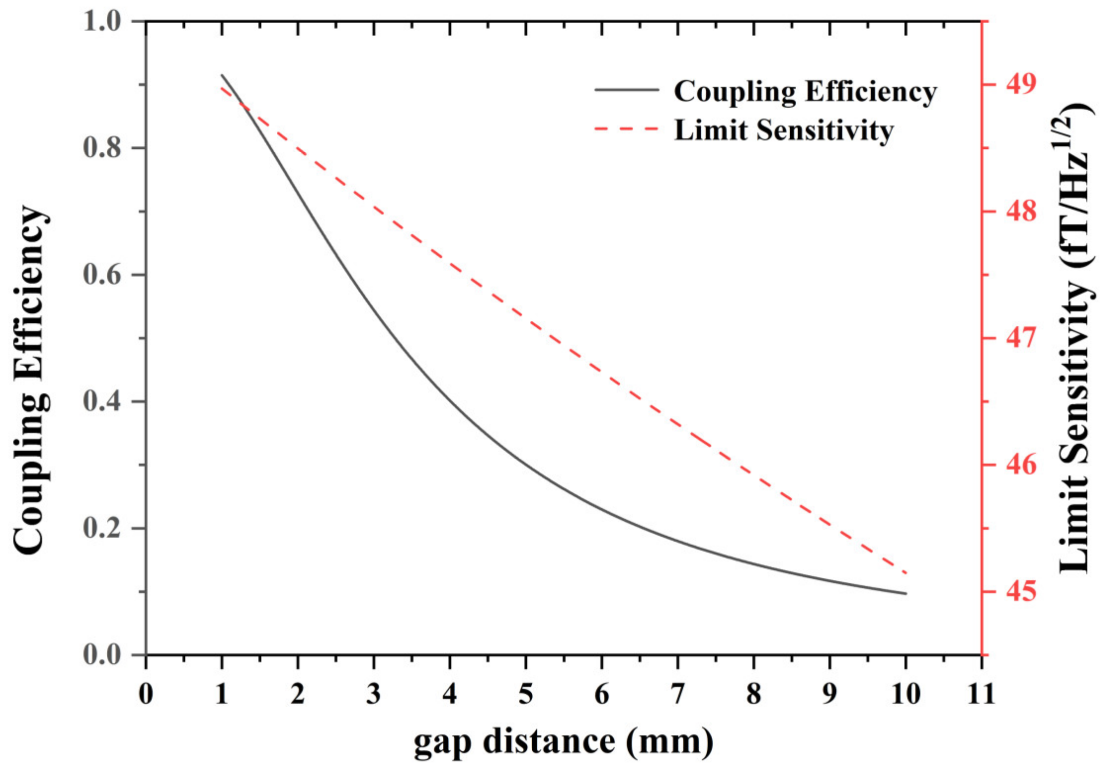
where ω 1 z is the spot radius of the incident Gaussian beam in z direction, ω 1 is the optical waist radius, λ is the optical wavelength, x 0 is the transverse offset of the beam relative to the fiber core, ω 0 is the spot radius in the optical fiber core, which is approximately considered to be the radius of the fiber core. It is assumed that the parameters of the incident and the output fibers are the same, and the mode field diameter (MFD) is 40 × 10−6 μm. The light emitted from the input fiber is a Gaussian beam, which propagates along the z direction. The optical waist radius is approximately equal to the radius of the input fiber core, and the optical waist position is x 0 = 0 . The output fiber core is coaxial with the input fiber in z direction. The changes in the coupling efficiency of the output fiber in z directions and the limit sensitivity are simulated as shown in Figure 4.
Figure 4 shows the limit sensitivity and the coupling efficiency with the gap distance when the input and output fibers are of the same type. For the SERF AM, the sensitivity is inversely proportional to measured volume, as the function of 1 / V , which increases with the air gap. The limit sensitivity is 48.18 fT/Hz1/2 for 1 mm air gap and increases to 45.15 fT/Hz1/2 with a larger air gap. However, the light is difficult to collect for a larger gap, noting that transverse displacement and angle error are not considered in this case. However, when the air gap is 2.68 mm, the coupling efficiency decreases to 60%, which can hardly tolerate the offset and slant angle of the fiber errors. Due to the attenuation of coupling efficiency, 1 mm gap is suitable for the fiber cell.
Figure 5 shows the coupling efficiency and limit sensitivity with 1 mm and 2.68 mm air gaps. For a 1 mm air gap, with the increase in fiber core diameter, the coupling efficiency in the black solid line first rapidly increases increases. When the core diameter exceeds 40 μm, it slows down and gradually becomes saturated, which means that the fiber core with a small diameter has a small acceptance angle and loses most of the incident light. The limit sensitivity in the blue dot line increases with a larger fiber diameter, which reaches 19.6 fT/Hz1/2 with a 100 μm fiber diameter, but the 40 μm fiber diameter may be suitable considering the actual manufacture. For comparation, the black dot line and red solid line are the coupling efficiency and limit sensitivity of the fiber cell with 2.68 mm air gap. The limit sensitivity changes slightly, as the 5 cm long HC-PCF is much larger than the air gap. Thus, the coupling efficiency may be a key consideration for air gap. For this reason, the coupling efficiency under different core diameters as the function of the air gap was simulated as shown in Figure 6.
As can be seen from the simulation results in Figure 6, the decreasing rates of coupling efficiency with a 40 μm diameter black solid line slowly drops compared with the other two fiber cells. Moreover, the larger fiber core ensures a larger coupling efficiency due to a larger beam spot. Among the three kinds of simulated fibers, the 4.5 μm core diameter corresponds to the PMF, the 9 μm corresponds to the common single-mode fiber, and the 40 μm represents the commercial HC-PCF. The coupling efficiency sharply decreases for small fiber cores of below 9 μm. For fiber with a diameter of 40 μm, the coupling efficiency is 90% at 1 mm air gap and remains 60% at 2.69 mm. The results show that although PMF is necessary for fiber interference detection, it is not conducive to fiber coupling due to its small core diameter. Thus, HC-PCFs spliced with PMFs are considered as the input and output fibers of fiber cell. The fusion of PMF with various kinds of fibers is simple and operable.
In practice, the relative position of the fiber is not ideal for transverse offset x 0 and tilt angle error θ , as shown in Figure 7. According to this situation, the formula of fiber coupling efficiency is modified as
η = κ exp κ x 0 2 2 1 / ω w a i s t 2 + 1 / ω 0 2 + π 2 θ 2 ω 1 2 z + ω 0 2 / 2 λ 2 x 0 θ z / ω w a i s t 2
According to Equation (7), the coupling efficiency changes with different transverse and tilt angles were simulated as shown in Figure 8.
Figure 8 shows the influence of the transverse offset and tilt angular of the output fiber on the coupling efficiency of the HC-PCFs with a 40 μm core diameter. The coupling efficiency is 91% in ideal situation and decreases with the increase in offset and tilt Angle. For SERF AM, the tolerance of coupling efficiency is set at 60%, which means that the tolerance of the tilt angle is less than 0.003° and the transverse offset is less than 1.23 × 10⁻⁵ m.

3.3. The Coating of the Fiber Cell

The atoms lose coherence after colliding with the cell wall. The coating preserves the polarization of atoms after the wall collision [26]. Octadecyltrichlorosilane (OTS) is the first known anti-relaxation coating for polarized alkali vapor [27]. OTS is added to the solution containing one part chloroform to four parts hexanes by volume at a concentration of 0.8 mL OTS per 1 L of the solution. The HC-PCF is exposed to the OTS solution for five minutes, during which time OTS molecules attach to the SiO2. The chlorine atoms in the trichlorosilane end group react with OH groups on the surface to form HCl, and then the silicon atom binds to the oxygen atoms remaining on the surface [28]. Coating for the cell allows for atoms to bounce up to 10,000 times off the cell wall without depolarizing. The coating would improve the limit sensitivity for fiber atomic cells. The wall relaxation of the atoms in the coating cell is simulated. The decay of the polarization is given by the diffusion equation and the number of bounces, N, which indicates the times at which atoms collide with the cell wall without losing the coherence, as follows:
P r = v ¯ P 2 N 2 1 / N D
where D scales inversely with buffer gas pressure and is thus given relative to its value D0 at a pressure p0 by D = D0·p0/p. The solution to the diffusion equation for the fundamental diffusion mode is given by the following system of equations, which may be solved numerically:
k cot k a = 1 a v ¯ 2 N 2 1 / N D
R w a l l = D k 2
v = 8 k B T π m
where k is the radial diffusion wave number; k B is the Boltzmann constant; m is the atomic mass; T is the cell temperature. The geometry of the fiber cell is simplified to a cylinder. The diameter of the fiber cell is 40 μm, the length of the air gap is 1 mm. The small diameter limits the wall relaxation, which is much larger than the relaxation due to spin destructive collisions. The total relaxation of the fiber cell is then approximated so that only the wall relaxation is considered.
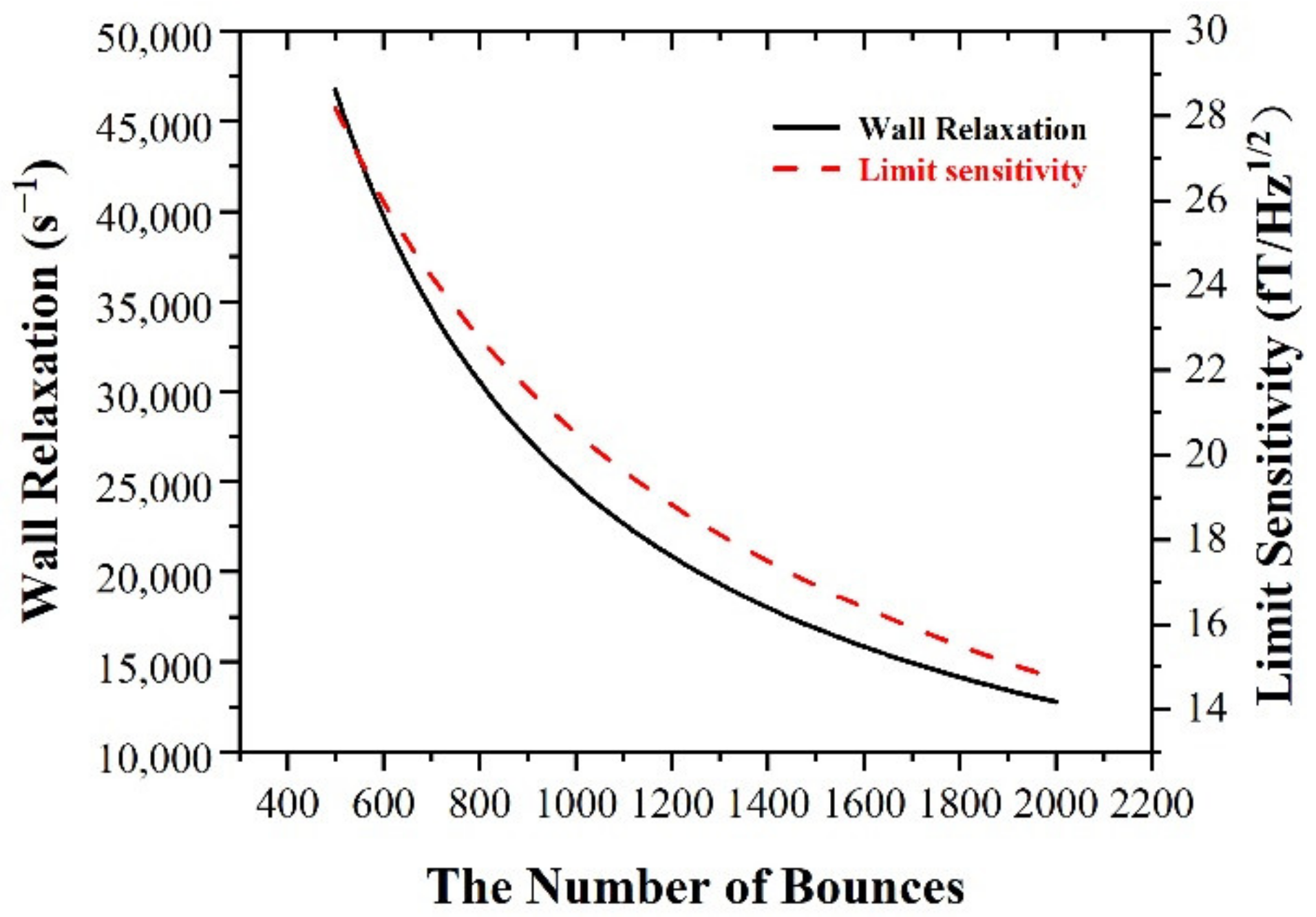
Figure 9 shows the wall relaxation and limit sensitivity of the fiber cell for potassium. The wall relaxation and limit sensitivity decrease with N. When the number of bounces is 450, the limit sensitivity of the fiber cell is 28.2 fT/Hz1/2, which is acceptable but limits the applications in magnetoencephalography. When the bounces decrease up to 2000, the wall relaxation decreases to 12,764 s−1 and the limit sensitivity reaches nearly 14.7 fT/Hz1/2, which can be used in magnetoencephalography applications. Although the relaxation of spin destruction will domain the limit sensitivity when the bounces reach 1.33 × 10⁵, the production of coatings with bounces larger than 2000 becomes difficult. According to Equations (9) and (10), the wall relaxation rate is a nonlinear function with the pressure of the buffer gas and the number of bounces. For miniature fiber cell, the pressure of the buffer gas influences not only the wall relaxation, but also the vacuum of the seal. The simulation results show a minor influence of the wall relaxation compared with the number of bounces.

4. Conclusions

Fiber AM is an important branch of the miniaturization of AM. The fiber alkali vapor cell is the limit for all fiber AM, which shows significance. The fiber cell designed in this work utilizes special fiber structure integrated with a conventional T-shape glass cell. Both the input and output fibers are composed of PMFs and HC-PCFs. The optical fiber structure is convenient for integration with various optical fiber systems, and the polarization preserving characteristics for PMF can meet the various requirements of quantum-sensing and quantum-precision measurements. It adopts T-shape glass tube structure to fill alkali metal and buffer gas, which has the advantages of filling flexibility and good sealing performances. The alignment structure of the HC-PCFs can ensure the large interaction volume of light and atoms to the greatest extent and reduce the insertion loss. The structure of PMF is easy to integrate into most of the current optical fiber systems. According to simulations, the fiber cell with a 40 μm diameter of the HC-PCF and 1 mm air gap has a wall relaxation of 2.88 × 10⁵ s−1 and a limit sensitivity of 48.2 fT/Hz1/2. Under this condition, the fiber cell faces 91% power loss due to fiber coupling. The tolerance of the tilt angle and transverse offset between fibers is 0.003° and 1.23 × 10⁻⁵ m for 60% coupling efficiency, respectively. Using the coating technique, the wall relaxation is 12,764 s−1 and the limit sensitivity can be improved to 14.7 fT/Hz1/2. The fiber cell can meet the needs of various optical fiber systems and has strong flexibility for fiber atomic spin precession detection systems, which will improve the spatial resolutions of AMs.

Author Contributions

Conceptualization: X.L. and Y.H.; methodology: X.L. and Y.L.; data analysis: X.W. and M.C.; writing and editing: X.L., Y.H., Y.L. and X.Z. All authors have read and agreed to the published version of the manuscript.

Funding

This work was supported by National Natural Science Foundation of China (NSFC) (No. 62005167).

Institutional Review Board Statement

Not applicable.

Informed Consent Statement

Not applicable.

Data Availability Statement

Not applicable.

Conflicts of Interest

The authors declare no conflict of interest.

References

  1. Syrjl, J.; Basti, A.; Guidotti, R.; Marzetti, L.; Pizzella, V. Decoding working memory task condition using magnetoencephalography source level long-range phase coupling patterns. J. Neural. Eng. 2021, 18, 016027. [Google Scholar] [CrossRef] [PubMed]
  2. Falet, J.P.R.; Cté, J.; Tarka, V.; Martinez-Moreno, Z.E.; Voss, P.; Villers-Sidani, E.D. Mapping the human auditory cortex using spectrotemporal receptive fields generated with magnetoencephalography. NeuroImage 2021, 238, 118222. [Google Scholar] [CrossRef] [PubMed]
  3. Kim, K.; Begus, S.; Xia, H.; Lee, S.K.; Jazbinsek, V.; Trontelj, Z.; Romalis, M.V. Multi-Channel Atomic Magnetometer for Magnetoencephalography: A Configuration Study. NeuroImage 2014, 89, 143. [Google Scholar] [CrossRef] [PubMed]
  4. Vennemann, T.; Jeong, M.; Yoon, D.; Magrez, A.; Berger, H.; Yang, L.; Živković, I.; Babkevich, P.; Rønnow, H.M. Note: Commercial SQUID Magnetometer-Compatible NMR Probe and its Application for Studying a Quantum Magnet. Rev. Sci. Instrum. 2018, 89, 46101. [Google Scholar] [CrossRef]
  5. Dang, H.B.; Maloof, A.C.; Romalis, M.V. Ultra-high sensitivity magnetic field and magnetization measurements with an atomic magnetometer. Appl. Phys. Lett. 2010, 97, 227. [Google Scholar] [CrossRef] [Green Version]
  6. Shah, V.; Romalis, M.V. Spin-Exchange-Relaxation-Free Magnetometry Using Elliptically-Polarized Light. Phys. Rev. A 2009, 80, 13416. [Google Scholar] [CrossRef] [Green Version]
  7. Kitching, J. Chip-scale atomic devices. Appl. Phys. Rev. 2018, 5, 031302. [Google Scholar] [CrossRef]
  8. Wang, X.; Ye, M.; Lu, F.; Mao, Y.; Tian, H.; Li, J. Recent Progress on Micro-Fabricated Alkali Metal Vapor Cells. Biosensors 2022, 12, 165. [Google Scholar] [CrossRef]
  9. Hu, J.; Lu, J.; Liang, Z.; Liu, L.; Wang, W.; Zhou, P.; Ye, M. Integrated Polarization-Splitting Grating Coupler for Chip-Scale Atomic Magnetometer. Biosensors 2022, 12, 529. [Google Scholar] [CrossRef]
  10. Mhaskar, R.; Svenja, K.; John, K. A low-power, high-sensitivity micromachined optical magnetometer. Appl. Phys. Lett. 2012, 101, 241105. [Google Scholar] [CrossRef]
  11. Osborne, J.; Orton, J.; Alem, O.; Shah, V. Fully integrated standalone zero field optically pumped magnetometer for biomagnetism. In Proceedings of the Steep Dispersion Engineering and Opto-Atomic Precision Metrology XI, San Francisco, CA, USA, 29 January–1 February 2018; p. 210548. [Google Scholar] [CrossRef]
  12. Liu, X.; Yang, Y.; Ding, M.; Quan, W.; Hu, Y.; Li, Y.; Jin, W.; Fang, J. Single-fiber Sagnac Interferometer for Atomic Spin Precession Detection. J. Lightwave Technol. 2019, 37, 1317. [Google Scholar] [CrossRef]
  13. Tian, Y.; Wang, Z.; Wang, L. Hollow fibers: From fabrication to applications. Chem. Commun. 2021, 57, 9166–9177. [Google Scholar] [CrossRef]
  14. Ritter, R.; Gruhler, N.; Pernice, W.; Kübler, H.; Pfau, T.; Löw, R. Atomic vapor spectroscopy in integrated photonic structures. Appl. Phys. Lett. 2015, 107, 041101. [Google Scholar] [CrossRef] [Green Version]
  15. Epple, G.; Joly, N.Y.; Euser, T.G.; Russell, P.S.J.; Loew, R. Effect of stray fields on Rydberg states in hollow-core PCF probed by higher-order modes. Opt. Lett. 2017, 42, 3271. [Google Scholar] [CrossRef] [Green Version]
  16. Veit, C.; Epple, G.; Kübler, H.; Euser, T.G.; Russell, P.S.J.; Löw, R. RF-dressed Rydberg atoms in hollow-core fibres. J. Phys. B 2016, 49, 134005. [Google Scholar] [CrossRef] [Green Version]
  17. Donvalkar, P.S.; Ramelow, S.; Clemmen, S.; Gaeta, A.L. Continuous generation of rubidium vapor in hollow-core photonic bandgap fibers. Opt. Lett. 2015, 40, 5379. [Google Scholar] [CrossRef] [Green Version]
  18. Slepkov, A.D.; Bhagwat, A.R.; Venkataraman, V.; Londero, P.; Gaeta, A.L. Generation of large alkali vapor densities inside bare hollow-core photonic band-gap fibers. Opt. Express 2008, 16, 18976. [Google Scholar] [CrossRef]
  19. Vogl, U.; Peuntinger, C.; Joly, N.Y.; Russell, P.S.J.; Marquardt, C.; Leuchs, G. Atomic mercury vapor inside a hollow-core photonic crystal fiber. Opt. Express 2014, 22, 29375. [Google Scholar] [CrossRef] [Green Version]
  20. Kaczmarek, K.T.; Saunders, D.J.; Sprague, M.R.; Kolthammer, W.S.; Feizpour, A.; Ledingham, P.M.; Brecht, B.; Poem, E.; Walmsley, I.A.; Nunn, J. Ultrahigh and persistent optical depths of cesium in Kagomé-type hollow-core photonic crystal fibers. Opt. Lett. 2015, 40, 5582. [Google Scholar] [CrossRef]
  21. Gutekunst, J.; Weller, D.; Kübler, H.; Negel, J.; Ahmed, M.A.; Graf, T.; Löw, R. Fiber-integrated spectroscopy device for hot alkali vapor. Appl. Opt. 2017, 56, 5898. [Google Scholar] [CrossRef] [Green Version]
  22. Kamra, A.; Ghosh, B.; Ghosh, T.K. Spin Relaxation due to Electron–Electron Magnetic Interaction in High Lande g-Factor Semiconductors. J. Appl. Phys. 2010, 108, 54505. [Google Scholar] [CrossRef] [Green Version]
  23. Budker, D.; Romalis, M. Optical magnetometry. Nat. Phys. 2007, 3, 227–234. [Google Scholar] [CrossRef] [Green Version]
  24. Sander, T.H.; Preusser, J.; Mhaskar, R.; Kitching, J.; Trahms, L.; Knappe, S. Magnetoencephalography with a chip-scale atomic magnetometer. Biomed. Opt. Express 2012, 3, 981–990. [Google Scholar] [CrossRef]
  25. Seltzer, S.J. Developments in Alkali-Metal Atomic Magnetometry. Ph.D. Thesis, Princeton University, Princeton, NJ, USA, 2008. [Google Scholar]
  26. Seltzer, S.J.; Romalis, M.V. High-temperature alkali vapor cells with antirelaxation surface coatings. J. Appl. Phys. 2009, 106, 114905. [Google Scholar] [CrossRef] [Green Version]
  27. Rampulla, D.M.; Oncel, N.; Abelev, E.; Yi, Y.W.; Knappe, S.; Bernasek, S.L. Effects of organic film morphology on the formation of Rb clusters on surface coatings in alkali metal vapor cells. Appl. Phys. Lett. 2009, 94, 103116. [Google Scholar] [CrossRef] [Green Version]
  28. Rosen, M.S.; Chupp, T.E.; Coulter, K.P.; Welsh, R.C.; Swanson, S.D. Polarized 129Xe optical pumping/spin exchange and delivery system for magnetic resonance spectroscopy and imaging studies. Rev. Sci. Instrum. 1999, 70, 1546–1552. [Google Scholar] [CrossRef]
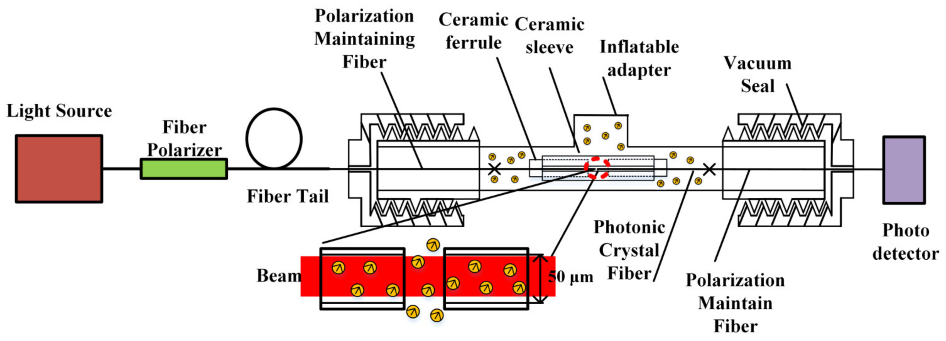
Figure 1. The schematic of the proposed fiber alkali vapor cell and setup.
Photonics 09 00749 g001
Figure 2. The relaxation of wall collision with the diameter of the fiber.
Photonics 09 00749 g002
Figure 3. The principle of fiber coupling with Gaussian beam.
Photonics 09 00749 g003
Figure 4. The limit sensitivity and the coupling efficiency with the gap distance.
Photonics 09 00749 g004
Figure 5. The coupling efficiency with the diameter of the fiber.
Photonics 09 00749 g005
Figure 6. The fiber coupling efficiency with different fiber diameter.
Photonics 09 00749 g006
Figure 7. The fiber coupling influenced with the axial error.
Photonics 09 00749 g007
Figure 8. The coupling efficiency with different angular and transverse offsets.
Photonics 09 00749 g008
Figure 9. The relaxation of the fiber cell with coating.
Photonics 09 00749 g009
Publisher’s Note: MDPI stays neutral with regard to jurisdictional claims in published maps and institutional affiliations.