Article

Optical Vortex Beams with a Symmetric OAM Spectrum beyond a Sector Aperture

by
Victor V. Kotlyar
1,2,
Alexey A. Kovalev
1,2,* and
Anton G. Nalimov
1,2
1
Image Processing Systems Institute of the RAS—Branch of FSRC “Crystallography & Photonics” of the RAS, 151 Molodogvardeyskaya St., 443001 Samara, Russia
2
Technical Cybernetics Department, Samara National Research University, 34 Moskovskoe shosse, 443086 Samara, Russia
*
Author to whom correspondence should be addressed.
Photonics 2022, 9(10), 734; https://doi.org/10.3390/photonics9100734
Submission received: 9 September 2022 / Revised: 30 September 2022 / Accepted: 5 October 2022 / Published: 7 October 2022
(This article belongs to the Special Issue Recent Advances in Optical Diffraction and Imaging)

Abstract

:
In this work, we theoretically and numerically show that in the superposition of optical Gaussian vortices with a symmetric OAM spectrum, the normalized orbital angular momentum (OAM) carried by the beam and the topological charge (TC) equal TC of the middle constituent vortex. We also show that after passing a sector-shaped aperture, the symmetric superposition preserves the OAM carried, with the TC becoming fractional and proportional to the angle of the sector aperture. As it further propagates in free space after the sector aperture, the TC of the superposition becomes an integer, albeit indefinite, thanks to the aperture edges generating a multitude of extra optical vortices with positive and negative unit TC, irregularly arranged across the beam.

1. Introduction

Orbital angular momentum (OAM) and topological charge (TC) are key parameters that characterize optical vortex laser beams [1]. In Laguerre–Gaussian (LG) vortex beams, the normalized-to-power OAM is known to equal the TC, denoted as l [2]. LG beams, as well as some other familiar vortex beams, including Bessel–Gaussian [3], Hypergeometric [3,4], Hypergeometric–Gaussian [5,6], and circular [7] beams are characterized by homogeneous OAM density. Therefore, for such beams, whose complex amplitude is expressed as A(r,z)exp(i) through the cylindrical coordinates (r, φ, z), the normalized OAM equals TC = l at any point of their cross-section. It stands to reason that after passing through an arbitrary-shaped aperture, the density of the normalized OAM carried by such beams remains unchanged and equals l, and so does the total normalized OAM = l. Hence, we conclude that, irrespective of the shape of the aperture through which the beam A(r,z)exp(i) passes, the normalized OAM is carries remains unchanged. It has been demonstrated [8] that when passing an on-axis superposition of vortex beams through a sector-shaped aperture, the OAM preserved just at certain values of angles of the sector aperture. Superposition of optical vortices with symmetric OAM spectrum has been shown to carry the normalized OAM equal to the TC of the middle constituent optical vortex [9]. Hence, vortex beams with symmetric OAM spectrum feature the homogeneous density of the OAM which is equal to the TC of the middle (central) constituent optical vortex. We may conjecture that given a vortex beam with symmetric OAM spectrum, no sector aperture will change the OAM value.
In this work, we show that after passing through an arbitrary-angle sector aperture, the normalized OAM carried by superposition of optical vortices with symmetric OAM spectrum remains unchanged. As a follow-up to work [9], we also show that in the on-axis superposition of optical vortices with symmetric OAM spectrum, the TC equals that of the middle constituent beam. Hence, we may infer that all optical vortices with a symmetric OAM spectrum that have the same TC of the middle constituent vortex carry the same OAM and have the same TC, with both being equal to the TC of the middle constituent vortex. When passed through a sector aperture, such superposition of laser optical vortices can be utilized as specially encoded beams providing stable data transmission (thanks to wide OAM spectrum) through a turbulent medium, while boasting high-density data transmission (owing to mutual orthogonality) and enhanced security (owing to sector-aperture-aided encoding). Improving techniques for noise reduction upon optical signal transmission through turbulent media, including atmosphere [10,11], under water [12], turbulent plasma [13,14], ultrasound turbulence [15], has been a highly relevant task [16,17,18,19].

2. Orbital Angular Momentum of Superposition of Vortices with Symmetric Spectrum

The complex amplitude of a source light field generated by superposition of Gaussian optical vortices may be given by
E ( r , φ ) = exp ( r 2 w 2 + i n 0 φ ) n = N N C n exp ( i n φ ) , C n = | C n | exp ( i φ n ) , φ 0 = 0 .
In (1), w is the radius of the Gaussian beam waist, Cn are complex weight coefficients, n0 is the middle TC, and (r, φ) are the polar coordinates. Assume the OAM spectrum of the superposition to be symmetric, i.e., C n = C n . Then, we can find the normalized-to-power OAM carried by the beam of Equation (1) using familiar formulae for a linearly polarized paraxial beam that define the OAM Jz and power W of the beam [20]:
J z = i 0 0 2 π E ( r , φ ) φ E ( r , φ ) r d r d φ , W = 0 0 2 π E ( r , φ ) E ( r , φ ) r d r d φ .
Substituting (1) into (2) yields:
J z = 0 exp ( 2 r 2 w 2 ) r d r 0 2 π n = N N m = N N C n C m ( n 0 + m ) exp [ i ( m n ) φ ] d φ = 2 π W 0 n = N N ( n 0 + n ) | C n | 2 = n 0 W + 2 π W 0 n = N N n | C n | 2 = n 0 W , W = 2 π 0 exp ( 2 r 2 w 2 ) r d r n = N N | C n | 2 = 2 π W 0 n = N N | C n | 2 .
In (3), the last equality in the relationship for Jz follows from the symmetry condition for the OAM spectrum:
n = N N n | C n | 2 = n = 1 N n ( | C n | 2 | C n | 2 ) = 0 .
Thus, from (3) it follows that the normalized OAM carried by superposition (1) equals the TC of the middle constituent beam:
J z W = n 0 .

3. Topological Charge of Superposition of Vortices with Symmetric OAM Spectrum

The simple form of the relationship (5) for the normalized OAM suggests an idea that the TC of superposition (1) would also be equal to that of the middle beam, i.e., n0. Let us prove this conjecture. Using the symmetry condition, C n = C n , Equation (1) is rearranged into:
E ( r , φ ) = exp ( r 2 w 2 + i n 0 φ ) ( C 0 + 2 n = 1 N | C n | cos ( n φ + φ n ) ) = A ( r , φ ) exp ( i n 0 φ ) , Im ( A ( r , φ ) ) = 0 .
Equation (6) suggests that superposition (1) can be represented as an angular harmonic exp ( i n 0 φ ) , whose TC equals the middle TC, multiplied by a real function A ( r , φ ) . Let us demonstrate that the TC of such a light field equals n0. The TC can be calculated using M. Berry’s formula [21]:
T C = 1 2 π lim r Im 0 2 π d φ E ( r , φ ) / φ E ( r , φ ) .
In (7), ‘lim’ stands for the limit when tending the radial variable to infinity and Im is the imaginary part of the number. Substituting (6) into (7) yields:
T C = 1 2 π lim r Im 0 2 π d φ ( A ( r , φ ) / φ + i n 0 A ( r , φ ) ) exp ( i n 0 φ ) A ( r , φ ) exp ( i n 0 φ ) = n 0 + 1 2 π lim r Im 0 2 π d φ ( A ( r , φ ) / φ ) A ( r , φ ) = n 0 .
The last equality in (8) follows from the fact that the imaginary part of the integral equals zero because the integrand is a real function. Hence, we have proven that the TC of superposition of optical vortices with symmetric OAM spectrum in Equation (1) equals that of the middle constituent beam:
T C = n 0 .

4. Conservation of the OAM Carried by a Field with Symmetric OAM Spectrum after Passing through a Sector Aperture

Similar to Equation (3), it is possible to derive an expression to describe the normalized OAM carried by field (1) having passed through a sector aperture with the angle 2α, located symmetrically relative to the x-axis. Unlike Equation (3), the integration with respect to the polar angle needs to be performed over a sector with angle 2α, and not over the closed circle. Another requirement is that the weight coefficients in the superposition Im Cn = 0 should be real. Thus, substituting (1) into (2) yields:
J z , α = 0 exp ( 2 r 2 w 2 ) r d r n = N N m = N N C n C m ( n 0 + m ) α α exp [ i ( m n ) φ ] d φ = 4 α π W 0 n = N N m = N N C n C m ( n 0 + m ) sinc [ ( n m ) α ] , W = 4 α π W 0 n = N N m = N N C n C m sinc [ ( n m ) α ] .
In (10), sinc(x) = sin(x)/x. The normalized OAM will be given by
J z , α W = n = N N m = N N C n C m ( n 0 + m ) sinc [ ( n m ) α ] n = N N m = N N C n C m sinc [ ( n m ) α ] = n 0 + n = N N m = N N C n C m m sinc [ ( n m ) α ] n = N N m = N N C n C m sinc [ ( n m ) α ] = n 0 .
The last equality in (11) results from the symmetry condition for the OAM spectrum and the fact that the sinc-function is even:
m = 1 N m C m n = N N C n { sinc [ ( n m ) α ] sinc [ ( n + m ) α ] } = m = 1 N m C m n = 1 N C n { sinc [ ( n m ) α ] sinc [ ( n + m ) α ] + sinc [ ( n + m ) α ] sinc [ ( n m ) α ] } = 0 .
Thus, Equation (11) suggests that given that ImCn = 0, the normalized OAM carried by field (1) is preserved after passing through a sector aperture with an arbitrary angle 2α.

5. Topological Charge of Superposition with Symmetric OAM Spectrum after Passing through a Sector Aperture

Here, we demonstrate that immediately after a sector aperture with angle 2α, field (1) has the fractional TC = αn0/π. Substituting (1) into (7) yields:
T C = Re 2 π α α n = N N ( n 0 + n ) C n exp ( i n φ ) n = N N C n exp ( i n φ ) d φ = α π n 0 + Re 2 π α α 2 i n = 1 N n | C n | sin ( n φ + φ n ) C 0 + 2 n = 1 N | C n | cos ( n φ + φ n ) d φ = α π n 0 .
The last equality in (13) results from the fact that the integration produces a pure imaginary number, whereas there is a real-number sign in front of the integral, meaning that the entire second term is zero. Hence, it follows from (13) that immediately behind the sector aperture, the TC of superposition (1) becomes a real number. In the meantime, owing to the property of the complex amplitude being continuous upon free-space propagation, the TC needs to be integer.
Below, we demonstrate that upon free-space propagation, field (1) has an integer, albeit indefinite, TC. For simplicity, the source field is taken in the form of a single-ring Laguerre-Gaussian beam with its complex amplitude given by
E ( r , φ ) = exp ( r 2 w 2 + i m φ ) ( r w ) m .
The transmission of a symmetric sector aperture with the open-sector polar angle found in the interval α < φ < α can be given as an expansion into a Fourier series in terms of even harmonics:
sect ( φ , α ) = n = sin ( α n ) π n exp ( i n φ ) = 2 α π ( 1 2 + n = 1 ( sin ( α n ) α n ) cos ( n φ ) ) .
Then, after passing through the sector aperture of Equation (15), the source field of Equation (14) produces at the focus of a spherical lens the amplitude given by
E f ( ρ , θ ) = ( i k 2 π f ) 0 0 2 π E ( r , φ ) sect ( φ , α ) exp ( i k r ρ f cos ( φ θ ) ) r d r d φ ,
where f is the focal length of the spherical lens, k is the wavenumber, (ρ,θ) are the polar coordinates at the focus of the spherical lens. The integrals in (16) can be calculated using Kummer’s function:
E f ( ρ , θ ) = ( i ) m + 1 m ! ( α z 0 π f ) y m exp ( y 2 + i m θ ) × [ 1 + n = 1 sin ( α n ) α n { ( i ) n y n e i n θ Г ( m + 1 + n / 2 ) m ! ( m + n ) ! M ( n 2 , m + n + 1 , y 2 ) + i n y n e i n θ Г ( m + 1 n / 2 ) m ! ( m n ) ! M ( n 2 , m n + 1 , y 2 ) } ] ,
where y = k w ρ / ( 2 f ) , z 0 = k w 2 / 2 is the Rayleigh range, Γ(x) is the gamma-function, M(a,b,c) is Kummer’s function. According to Equation (7), for the TC of field (17) to be derived, it would suffice to know an asymptotic relation for the complex amplitude at ρ → ∞. The asymptotic relation can be found using an approximate expression for Kummer’s function at large values of the argument [22]:
M ( a , b , z > > 1 ) Г ( b ) Г ( a ) z a b exp ( z ) .
Then, at ρ >> 1, Equation (17) is rearranged to
E f ( ρ > > 1 , θ ) ( i ) m + 1 m ! ( α z 0 π f ) { y m exp ( y 2 + i m θ ) + e i m φ m ! y m + 2 [ n = 1 sin ( α n ) α n ( e i n θ ¯ Г ( m + 1 + n / 2 ) Г ( n / 2 ) + e i n θ ¯ Г ( m + 1 n / 2 ) Г ( n / 2 ) ) ] } ,
where θ ¯ = θ π / 2 is the polar angle with due regard for the 90-degree rotation of the entire intensity pattern in the far field. In (19), at large y, the first term in the curly brackets tends to zero faster thanks to the presence of decaying exponent when compared with the second term in the square brackets, which decays as y−(m + 2). So, it can be neglected in Equation (19). The ratio of Gamma functions in (19) can be replaced by Pochhammer symbols:
E f ( ρ > > 1 , θ ) ( i ) m ! ( α z 0 π f ) e i m θ ¯ m ! y m + 2 × [ n = 1 sin ( α n ) α n ( e i n θ ¯ ( n 2 ) m + 1 + e i n θ ¯ ( n 2 ) m + 1 ) ] } .
From Equation (20), the Pochhammer symbol (−n/2)m + 1 [22] is seen to equal zero at even numbers n = 2p, p = 1,2,3, etc., and at p < (m + 1), meaning that in superposition of optical vortices, several first angular harmonics with negative numbers will be missing. Moreover, in (20) all coefficients (n/2)m + 1 by the positive harmonics exp(inθ) are larger in the absolute value than the coefficients (−n/2)m + 1 by the negative harmonics exp(−inθ). Because of this, with superposition of vortices in (20) being infinite, the TC of field (20) will also be infinite when calculated along an infinite-radius circle based on Equation (7). However, when calculated along various finite-radius circles (as is the case in practice), the TC will take different values at different radii, thus being indefinite. It is worth noting that the number of vortices with a positive TC = +1 is larger than those with the negative TC = −1. We also note that in the vicinity of the optical axis, where the intensity is not too low, there are m optical vortices with TC = +1. The remaining optical vortices with opposite signs will be found at the beam periphery, where the intensity is near zero. Such peripheral vortices are impossible to detect experimentally, but can be visualized using the numerical modeling, as we demonstrate in the next section.

6. Simulation

6.1. Preservation of OAM after Diaphragm

Here, we demonstrate how a Gaussian beam with a symmetric OAM spectrum changes its shape when spectrum is changed by increasing the sidelobes and by widening. Figure 1a,b show the intensity distribution in the initial plane and at the Rayleigh range for a narrow three-component OAM spectrum, consisting mainly of a single component: C−1 = 0.05i, C0 = 1, C1 = −0.05i. Other computation parameters are the following: wavelength λ = 532 nm, waist radius of the Gaussian envelope w0 = 0.5 mm, central topological charge of the optical vortices n0 = 5. When the sidelobes in the OAM spectrum increase (C−1 = 0.1i, C0 = 1, C1 = −0.1i), the light ring becomes asymmetric, with one side being bright and the other side being pale (Figure 1c,d). The asymmetry further increases and the light ring transforms into a crescent (Figure 1e,f) with growing sidelobes in the OAM spectrum (C−1 = 0.3i, C0 = 1, C1 = −0.3i). When the OAM spectrum widens and includes five vortices instead of three (C−2 = 0.1eiπ/4, C−1 = 0.3i, C0 = 1, C1 = −0.3i, C2 = −0.1eiπ/4), the initial intensity distribution is rotated (Figure 1g), although it does not significantly change the intensity pattern at the Rayleigh range (Figure 1h). When the beam passes through a sector aperture with the half-angle α = 2π/3 (Figure 1i,j) and α = π/3 (Figure 1k,l), the intensity pattern at the Rayleigh range becomes initially a light arc (Figure 1j) and a light spot (Figure 1l).
As seen in Figure 1, both changes in the OAM spectrum and applying the sector aperture lead to significant changes in the intensity pattern. However, numerical computation of the normalized OAM Jz/W by Equation (2) yields nearly the same values: 5.0006 (Figure 1a–d), 5.0463 (Figure 1e,f), 5.0375 (Figure 1g,h), 4.9742 (Figure 1i,j), 4.9579 (Figure 1k,l). Thus, in all cases we numerically obtained the values nearly equal to 5.
In the above example, we considered a case when the OAM spectrum decays fast from the central component. Now we consider an opposite case, when the OAM spectrum consists of five components and has a nearly flat shape.
Figure 2 illustrates the intensity (columns 1 and 3) and phase (columns 2 and 4) distributions of the beam (1) in the initial plane (columns 1 and 2) and at the Rayleigh distance from it (columns 3 and 4), when the beam (1) is not truncated (row 1) or truncated by a sector aperture with the half-angle α = 2π/3 (row 2) and α = π/3 (row 3). Other computation parameters are the following: wavelength λ = 532 nm, waist radius of the Gaussian envelope w0 = 0.5 mm, central topological charge of the optical vortices n0 = 5, number of vortices in the superposition N = 5, weight coefficients in the superposition C−2 = 0.8eiπ/4, C−1 = 0.9eiπ/2, C0 = 1, C1 = 0.9eiπ/2, C2 = 0.8eiπ/4. The patterns in the initial plane were computed directly by Equation (1), whereas the patterns at the Rayleigh distance were computed by the numerical Fresnel transform, implemented as the convolution with using fast Fourier transforms.
As seen in Figure 2, sector aperture significantly affects the intensity distribution generated after free-space propagation. However, according to the theory, the normalized OAM Jz/W should be equal to 5 in all three cases. Numerical computation by Equation (2) yields the following values: 4.9854 (Figure 2a,b), 4.9514 (Figure 2c,d), 4.9759 (Figure 2e,f), 4.8730 (Figure 2g,h), 4.9840 (Figure 2i,j), 4.8711 (Figure 2k,l). Thus, in all cases we numerically obtained the values nearly equal to 5.

6.2. Integer TC of the Beam after Passing through a Sector Aperture

In this sub-section, we analyze changes in the arrangement of optical vortices that are generated both by the original vortex beam (Equation (14)) and by the sector aperture the beam is passing through. The numerical modeling was conducted for the waist radius of w = 1 μm, the wavelength of λ = 532 nm, the size of the entire source field of 20 × 20 μm, and the original TC of m = 5, using a nonparaxial Rayleigh-Sommerfeld integral. The field was bounded by a sector with the half-angle α = 150°, with the entire aperture being open at α = 180° (so that a sector with the half-angle 30° is cut out). Figure 3 depicts the above-described source field at α = 150°.
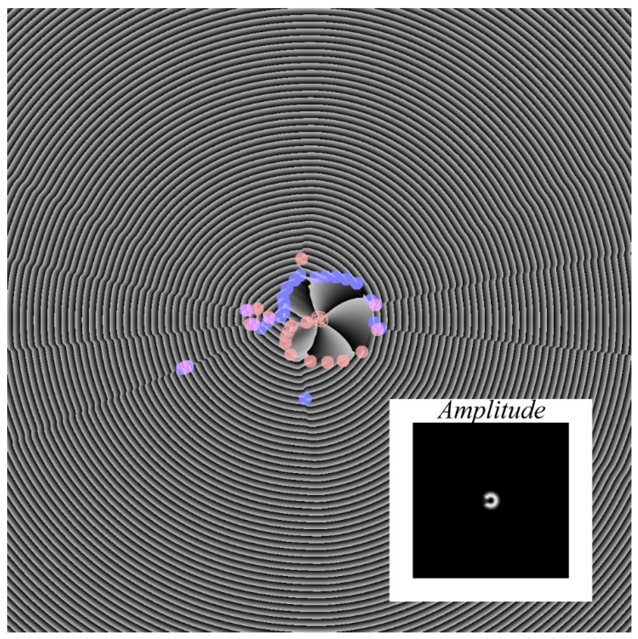
Figure 4 presents simulation results for the amplitude and phase at a distance of z = λ = 0.532 μm. The Rayleigh range is about z0 = 6 μm. From the phase pattern in Figure 4 it is seen that in the near field there are three optical vortices with TC +1 located in the vicinity of the optical axis, with an extra vortex with TC +1 found nearby, in the shadow zone. In addition, at some distance, above and below the optical axis, where the intensity is near zero, there are many optical vortices (intensity nulls) that have a positive TC (+1) below and a negative TC (−1) above the optical axis.
For comparison, Figure 5 depicts the phase of a complex-conjugated field relative to field (14) after passing through the aperture in (15) with the angle α = 150°, as in Figure 4. From a comparison of the phases in Figure 4 and Figure 5, the left edge of the sector aperture (the left edge dislocation) is seen to predominantly generate optical vortices with TC −1 (upper purple circles in Figure 4 and Figure 5), with the right edge of the sector aperture (the right edge dislocation) predominantly generating optical vortices with TC +1 (lower cyan circles in Figure 4 and Figure 5). It is interesting that this effect is independent of the sign of the TC of the incident optical vortex.
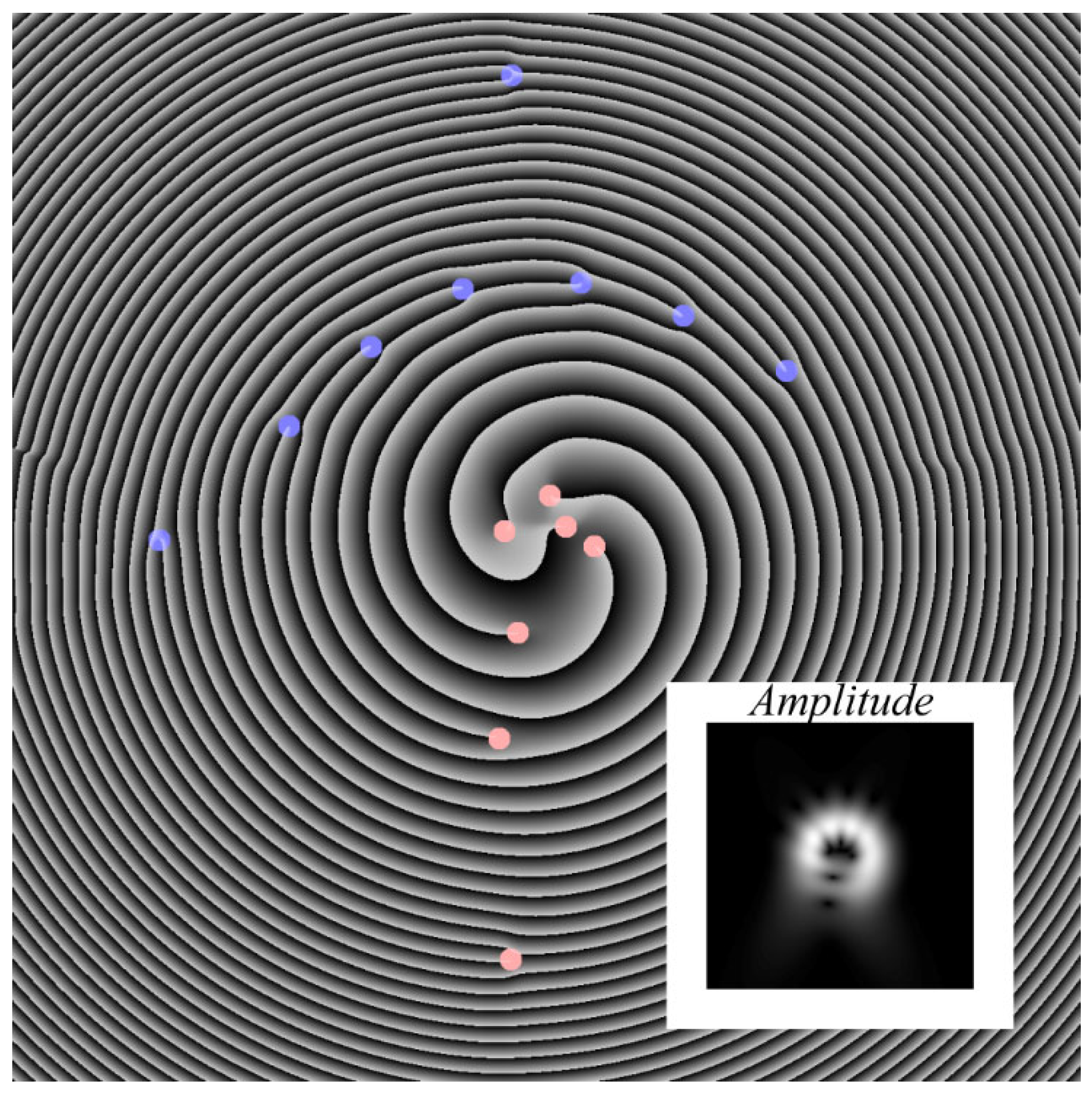
Figure 6 also shows the intensity and phase of the above-discussed light field, though not in the near field (z < z0), as is the case in Figure 4, but in the far field (z > z0) at a distance of z = 20 μm.
From Figure 6, the intensity and phase patterns are seen to rotate by about 90 degrees, also changing their form. While at the center, in the optical axis vicinity four optical vortices with TC +1 can be found as before, below the optical axis new optical vortices, namely, the fifth, sixth, and seventh, with TC +1 are seen to be born. In the meantime, above the optical axis, negative optical vortices with TC −1 are located. Altogether, in the phase pattern in Figure 6 there are seven positive vortices and eight negative vortices. However, this does not imply that the resulting TC of the entire field in Equation (16) equals 7 − 8 = −1. If the computation domain is increased, new optical vortices will be detected.
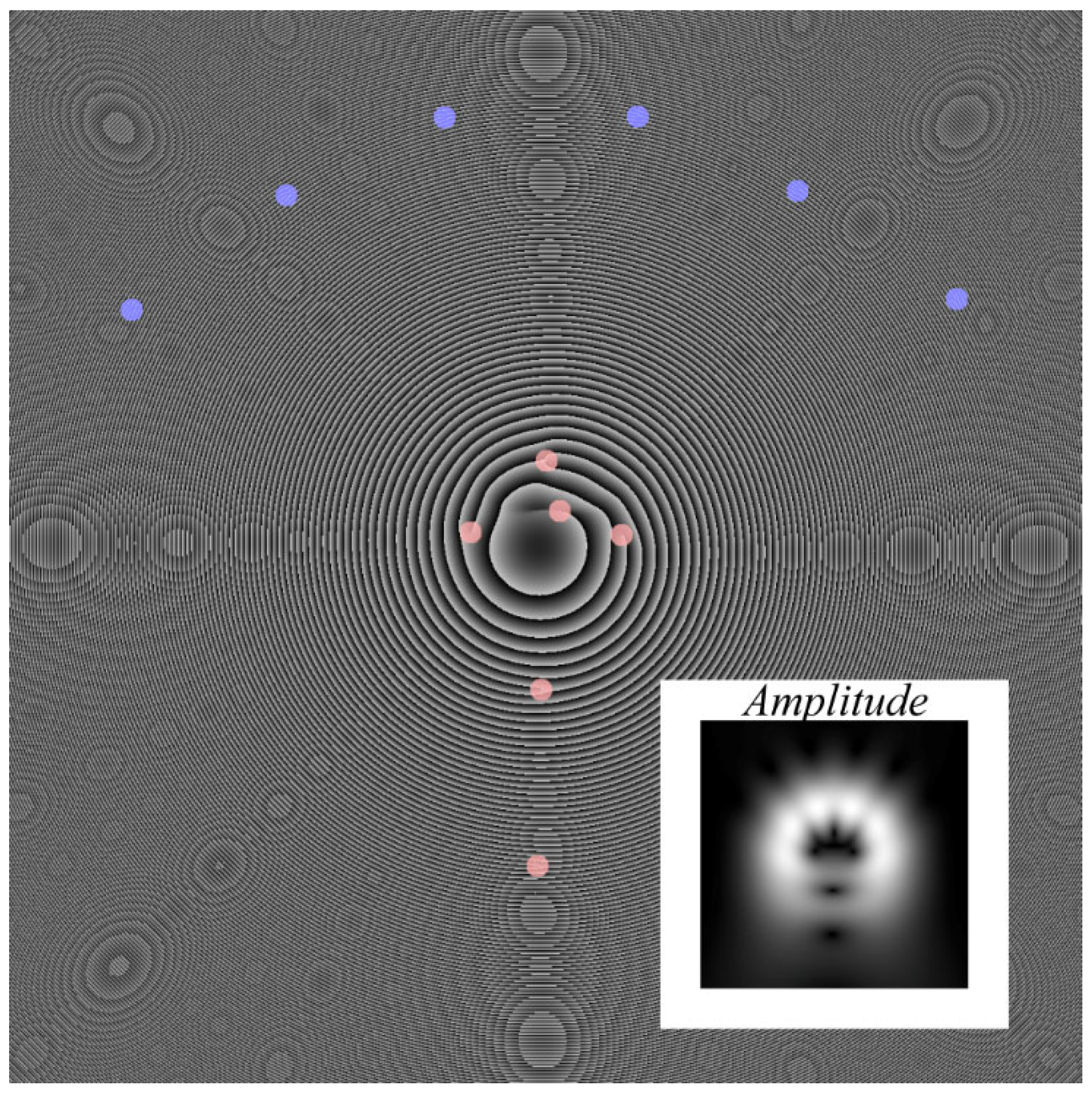
Figure 7 depicts intensity and phase patterns in the far field (z >> z0) at a distance of z = 200 μm. Considering that upon free-space propagation an optical Gaussian vortex diverges near linearly, practically the same optical vortices are found in Figure 7b as are in Figure 6, the only difference being the field size of 288 × 288 μm. One can see five positive vortices (m = 5) closest to the optical axis, with the sixth positive vortex being found below, at a significant distance from the center. Above the axis, six negative vortices are arranged in a semi-circle. The remaining optical vortices have not entirely vanished but have failed to be captured as they are at a large distance from the optical axis.
Thus, we can infer that closest to the optical axis are four positive vortices with TC +1, with their number being equal to the number of 2π-phase jumps (Figure 3b) that have made it through the aperture. With the fifth phase jump being cut-off by the aperture, the fifth vortex with positive TC +1 becomes visible in Figure 5 and Figure 6 at a larger distance from the optical axis compared with the main four vortices. In addition to the above-mentioned 4 + 1 vortices, aperture edges generate a multitude of extra positive and negative vortices, which are located still further away from the optical axis, in the region of near-zero intensity.
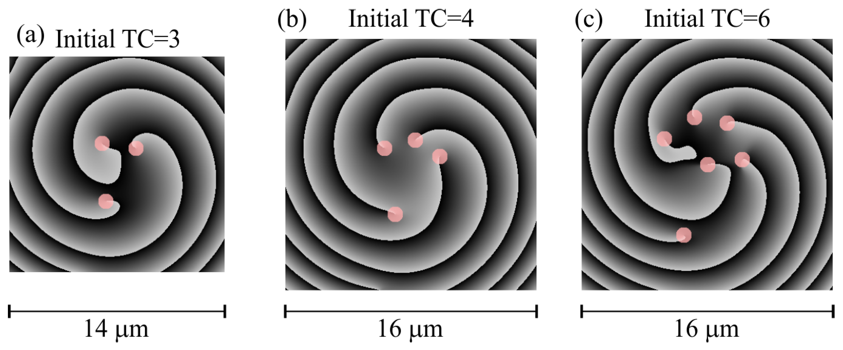
In addition, Figure 8 illustrates central areas of the phase distribution, similar to Figure 6, but for the following topological charges of the initial field (14): m = 3 (a), m = 4 (b), m = 6 (c). Other parameters are the same as in Figure 6 (m = 5). According to Figure 8, the number of phase singularities is equal to the initial TC of the light field (14). Thus, near the optical axis and at a distance from the initial plane (z = 20 μm), the TC of a light field after the aperture with the angle α = 150° is conserved.

7. Conclusions

To summarize, based on a theoretical and numerical analysis, we have demonstrated that the normalized OAM and the TC of superposition of Gaussian optical vortices with symmetric OAM spectrum are equal to the TC of the middle (central) constituent optical vortex. We have also shown that immediately after passing through a sector aperture, the OAM carried by symmetric superposition is conserved, with the TC becoming fractional and proportional to the angle of the sector aperture. As the beam further propagates in free space behind the sector aperture, the TC becomes integer albeit indefinite owing to aperture edges generating a multitude of extra optical vortices with positive and negative unit TC, which are arranged irregularly across the beam. Such laser beam superposition bounded by a sector-shaped aperture can be specially encoded for the stable data transmission through a turbulent medium, enabling high-density data transmission and enhanced security owing to the aperture disturbing (encoding) the beam in a designed manner. Using an aperture for encoding a data transmission channel in wireless telecommunications can be carried out not only in the optical wavelength range [19], but in the radio range as well [23].
In conclusion, we consider the following issue: why after a Laguerre–Gaussian beam passes through a sector aperture, its OAM is conserved, but the TC is indefinite. The OAM is conserved after the aperture since the Laguerre–Gaussian beam [2] and a beam with a symmetric OAM spectrum have the OAM density distributed uniformly in the beam cross-section, i.e., the OAM density is the same in each point of the beam section (of each photon). Therefore, when such a beam passes through an arbitrary-shape aperture, including a sector one, with the area size S, the full OAM is equal to nWs, where n is the beam TC and Ws is the beam energy passed through the aperture. Thus, the beam OAM, normalized to the beam energy, is equal to Jz/Ws = n.
The situation is different with the TC. The aperture edge can be treated as an edge dislocation, since the intensity is zero to the one side from the edge and nonzero to the other side from the aperture edge. In addition, there is an optical vortex inside the aperture. As demonstrated in several works [24,25,26], when the beam propagates in space, the edge dislocation and the optical vortex (screw dislocation) interact with each other, and this interaction generates a set of screw dislocations instead of the edge dislocation. Since the aperture edges extend from zero to infinity, the number of screw dislocations of both signs, born due to splitting the two edge dislocations (two aperture edges), is infinite. However, in the area near to the optical axis, where the intensity can be measured, there is a finite number of screw dislocations (isolated intensity nulls). Therefore, the TC of the light field after the aperture is indefinite, since its value depends on how many screw dislocations from the infinite number appears in the finite are of computation (or measurement).
We note that the OAM conservation after a Laguerre-Gaussian beam passes through an aperture does not contradict with the uncertainty principle between the two quantities—angular position φ and angular momentum (in this case the angular momentum is equal to the OAM density and to the topological charge n) [27]. On the one hand, it is shown in [27] that a decrease in the propagation angle Δφ of a beam leads to an increase in the width of the angular momentum density ΔJz. However, on the other hand, it is also demonstrated in [27], that a sector aperture, limiting a beam with a specific topological charge exp(i), whose center coincides with the aperture vertex, generates a light field with a symmetrically widened OAM spectrum. In the current work, we show that the normalized OAM and TC of a light field with a symmetric OAM spectrum is equal to the average (central) TC n. Thus, despite the aperture widens the beam OAM spectrum ΔJz, it is widened symmetrically, relative to the initial TC, and, therefore, the normalized OAM of the beam after the aperture remains unchanged Jz/Ws = n. It was proven experimentally in [28].

Author Contributions

Conceptualization, V.V.K.; methodology, V.V.K.; software, A.G.N. and A.A.K.; validation, V.V.K.; formal analysis, V.V.K.; investigation, V.V.K., A.G.N. and A.A.K.; resources, V.V.K.; writing—original draft preparation, V.V.K.; writing—review and editing, V.V.K.; visualization, A.G.N. and A.A.K.; supervision, V.V.K.; project administration, V.V.K.; funding acquisition, V.V.K. and A.A.K. All authors have read and agreed to the published version of the manuscript.

Funding

This research was funded by the Russian Science Foundation, grant number 22-12-00137.

Institutional Review Board Statement

Not applicable.

Informed Consent Statement

Not applicable.

Data Availability Statement

Not applicable.

Acknowledgments

We acknowledge the support of the Ministry of Science and Higher Education of the Russian Federation within a government project of the FSRC “Crystallography and Photonics” RAS.

Conflicts of Interest

The authors declare no conflict of interest.

References

  1. Kotlyar, V.V.; Kovalev, A.A.; Porfirev, A.P. Vortex Laser Beams; CRC Press: Boca Raton, FL, USA, 2018. [Google Scholar]
  2. Allen, L.; Beijersbergen, M.W.; Spreeuw, R.J.C.; Woerdman, J.P. Orbital angular momentum of light and the transformation of Laguerre–Gaussian laser modes. Phys. Rev. A 1992, 45, 8185–8189. [Google Scholar] [CrossRef] [PubMed]
  3. Gori, F.; Guattari, G.; Padovani, C. Bessel-Gauss beams. Opt. Commun. 1987, 64, 491–495. [Google Scholar] [CrossRef]
  4. Kotlyar, V.V.; Skidanov, R.V.; Khonina, S.N.; Soifer, V.A. Hypergeometric modes. Opt. Lett. 2007, 32, 742–744. [Google Scholar] [CrossRef]
  5. Karimi, E.; Zito, G.; Piccirillo, B.; Marrucci, L.; Santamato, E. Hypergeometric-Gaussian modes. Opt. Lett. 2007, 32, 3053–3055. [Google Scholar] [CrossRef] [PubMed] [Green Version]
  6. Kotlyar, V.V.; Kovalev, A.A. Family of hypergeometric laser beams. J. Opt. Soc. Am. A 2008, 25, 262–270. [Google Scholar] [CrossRef]
  7. Bandres, M.A.; Gutiérrez-Vega, J.C. Circular beams. Opt. Lett. 2008, 33, 177–179. [Google Scholar] [CrossRef] [Green Version]
  8. Kovalev, A.A.; Kotlyar, V.V. Orbital angular momentum of superpositions of optical vortices perturbed by a sector aperture. Photonics 2022, 9, 531. [Google Scholar] [CrossRef]
  9. Kotlyar, V.V.; Kovalev, A.A. Optical vortex beams with a symmetric and almost symmetric OAM spectrum. J. Opt. Soc. Am. A 2021, 38, 1276–1283. [Google Scholar] [CrossRef] [PubMed]
  10. Zhu, K.; Zhou, G.; Li, X.; Zheng, X.; Tang, H. Propagation of Bessel-Gaussian beams with optical vortices in turbulent atmosphere. Opt. Express 2008, 16, 21315. [Google Scholar] [CrossRef]
  11. Yuan, Y.; Lei, T.; Li, Z.; Li, Y.; Gao, S.; Xie, Z.; Yuan, X. Beam wander relieved orbital angular momentum communication in turbulent atmosphere using Bessel beams. Sci. Rep. 2017, 7, 42276. [Google Scholar] [CrossRef]
  12. Gruska, J. Propagation and self-healing properties of Bessel-Gaussian beam carrying orbital angular momentum in an underwater environment. Sci. Rep. 2019, 9, 2025. [Google Scholar]
  13. Li, J.; Yang, S.; Guo, L. Propagation characteristics of Gaussian beams in plasma sheath turbulence. IET Microw. Antennas Prop. 2017, 11, 280. [Google Scholar] [CrossRef]
  14. Chen, W.; Zhu, G.; Deng, Q.; Yang, L.; Li, J. Analysis of Gaussian beam broadening and scintillation index in anisotropic plasma turbulence. Waves Rand. Complex Media, 2022, in press. [CrossRef]
  15. Li, J.; Yang, S.; Guo, L.; Cheng, M. Anisotropic power spectrum of refractive-index fluctuation in hypersonic turbulence. Appl. Opt. 2016, 55, 9137. [Google Scholar] [CrossRef]
  16. Wang, J. Advances in communications using optical vortices. Photonics Res. 2016, 4, B14. [Google Scholar] [CrossRef] [Green Version]
  17. Wang, J.; Liu, J.; Li, S.; Zhao, Y.; Du, J.; Zhu, L. Orbital angular momentum and beyond in free-space optical communications. Nanophotonics 2022, 11, 645. [Google Scholar] [CrossRef]
  18. Willner, A.E.; Pang, K.; Song, H.; Zou, K.; Zhou, H. Orbital angular momentum of light for communications. Appl. Phys. Rev. 2021, 8, 041312. [Google Scholar] [CrossRef]
  19. Zhu, Z.; Janasik, M.; Fyffe, A.; Hay, D.; Zhou, Y.; Kantor, B.; Winder, T.; Boyd, R.W.; Leuchs, G.; Shi, Z. Compensation-free high-dimensional free-space optical communication using turbulence-resilient vector beams. Nat. Commun. 2021, 12, 1666. [Google Scholar] [CrossRef]
  20. Berry, M.V.; Jeffrey, M.R.; Mansuripur, M. Orbital and spin angular momentum in conical diffraction. J. Opt. A Pure Appl. Opt. 2005, 7, 685–690. [Google Scholar] [CrossRef]
  21. Berry, M.V. Optical vortices evolving from helicoidal integer and fractional phase steps. J. Opt. A Pure Appl. Opt. 2004, 6, 259–268. [Google Scholar] [CrossRef]
  22. Abramowitz, M.; Stegun, I.A. Handbook of Mathematical Functions: With Formulas, Graphs, and Mathematical Tables; National Bureau of Standards: Gaithersburg, MD, USA, 1965.
  23. Tamburini, F.; Mari, E.; Sponselli, A.; Thide, B.; Bianchini, A.; Romanato, F. Encoding many channels on the same frequency through radio vorticity: First experimental test. New J. Phys. 2012, 14, 033001. [Google Scholar] [CrossRef] [Green Version]
  24. Petrov, D.V. Vortex-edge dislocation interaction in a linear medium. Opt. Commun. 2001, 188, 307–312. [Google Scholar] [CrossRef]
  25. Petrov, D.V. Splitting of an edge dislocation by an optical vortex. Opt. Quantum Electron. 2002, 34, 759–773. [Google Scholar] [CrossRef]
  26. He, D.; Yan, H.; Lu, B. Interaction of the vortex and edge dislocation embedded in a cosh-Gaussian beam. Opt. Commun. 2009, 282, 4035–4044. [Google Scholar] [CrossRef]
  27. Franke-Arnold, S.; Barnet, S.M.; Yao, E.; Leach, J.; Courtial, J.; Padgett, M. Uncertainty principle for angular position and angular momentum. New J. Phys. 2004, 6, 103. [Google Scholar] [CrossRef] [Green Version]
  28. Volyar, A.V.; Akimova, Y.E. Transformations of structurally stable states of spiral beams subjected to sector perturbations. Comput. Opt. 2021, 45, 789–799. [Google Scholar] [CrossRef]
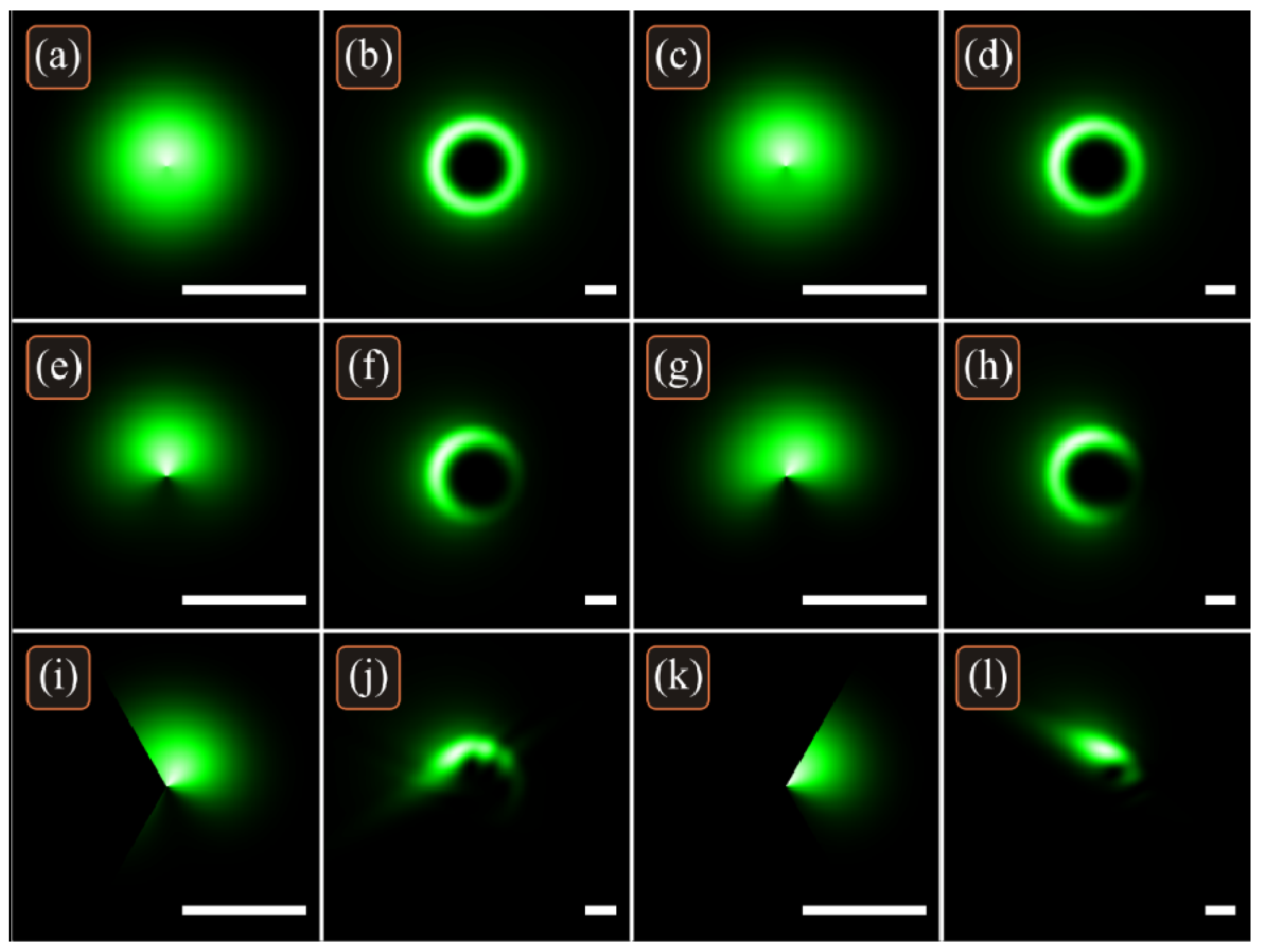
Figure 1. Intensity distributions of the beam (1) in the initial plane (columns 1 and 3) and at the Rayleigh distance from it (columns 2 and 4), when the side components in the OAM spectrum increase (af), when the OAM spectrum widens (g,h), and when the initial beam is truncated by a sector aperture (il). The length of the horizontal line segment is 1 mm.
Photonics 09 00734 g001
Figure 2. Intensity (columns 1 and 3) and phase (columns 2 and 4) distributions of the beam (1) in the initial plane (columns 1 and 2) and at the Rayleigh distance from it (columns 3 and 4), when the beam (1) is not truncated (ad) or truncated by two different sector apertures (el).
Photonics 09 00734 g002
Figure 3. An amplitude (a) and phase (b) of the incident field at α = 150°, 20 × 20 μm, TC m = 5.
Photonics 09 00734 g003
Figure 4. Amplitude (inset) and phase of the light field of Equation (14) having passed the sector aperture of Equation (15) with the angle α = 150° at a distance of z = λ behind the aperture. Positive dislocations are purple shaded circles and negative ones are within cyan shaded circles. Both amplitude and phase field sizes are 48 × 48 μm.
Photonics 09 00734 g004
Figure 5. Phase of a light field complex conjugated with field (14) after passing through aperture (15) with the angle α = 150° at a distance of z = λ behind the aperture. Positive dislocations are purple shaded circles and negative ones are within cyan shaded circles. The field size is 48 × 48 μm.
Photonics 09 00734 g005
Figure 6. Amplitude (inset) and phase of light field (14) after passing through aperture (15) with the angle α = 150° at a distance of z = 20 μm. Positive dislocations are purple shaded circles and negative ones are within cyan shaded circles. Both amplitude and phase field sizes are 48 × 48 μm.
Photonics 09 00734 g006
Figure 7. An amplitude (inset), phase at a distance of z = 200 μm. Positive dislocations are purple shaded circles and negative ones are within cyan shaded circles. Both amplitude and phase field sizes are 288 × 288 μm.
Photonics 09 00734 g007
Figure 8. Phase patterns represent optical vortices at a distance of z = 20 μm for different initial TC: 3 (a), 4 (b) and 6 (c). Positive dislocations are purple shaded circles. Field sizes are 14 × 14 μm for TC = 3, 16 × 16 μm for TC = 4 and 6.
Photonics 09 00734 g008
Publisher’s Note: MDPI stays neutral with regard to jurisdictional claims in published maps and institutional affiliations.