Abstract
In recent years, fiber gas lasers have obtained a rapid development, however, efficient and stable pump coupling is a key limitation for their applications in the future. Here, we report an all-fiber gas cavity based on anti-resonant hollow-core fibers which have the beneficial properties of adjustable broad transmission bands and potential low transmission attenuation, especially in the mid-infrared. This kind of all-fiber gas cavity is fabricated by directly splicing with end caps at both ends for the first time. The high-power laser transmission characteristics were studied, and the experimental results show that the all-fiber gas cavities have a very stable performance. The maximum input laser power at 1080 nm is about 260 W, and the output power is 203 W, giving a total transmission efficiency of 78.1%. This work opens a new opportunity for the development of high-power all-fiber structured fiber gas lasers.
1. Introduction
Anti-resonant hollow-core fibers (AR-HCFs) are a new kind of HCF with very simple structures, mainly including revolver type [1] and ice-cream type [2]. In the past decade, AR-HCFs have attracted rapid development due to the beneficial characteristics of broad and easily adjustable transmission bands, potential low transmission-loss, particularly in the mid-infrared range, etc. [3,4]. AR-HCFs provide an ideal environment for the interaction of laser beams and gases, making a novel kind of laser source, namely fiber gas lasers (FGLs) [5,6]. In the past few years, FGLs have obtained enormous attention because they have been demonstrated to be an effective new method for generating mid-infrared laser emission [5,6,7,8,9,10,11,12,13,14,15,16,17,18,19] in addition to traditional ways, such as solid-state lasers [20], gas lasers [21], quantum-cascade lasers [22] and rare-earth-doped fiber lasers [23,24,25]. Due to the perfect combination of the advantages of both gas lasers and fiber lasers, FGLs have the potential to achieve high-power mid-infrared lasers with abundant wavelengths and portable structures [6]. To date, the maximum output power for CW mid-infrared FGLs is 1 W at 3.1 μm [16], while for wavelengths above 4 μm it is only dozens of milliwatt [18], which is mainly limited by the maximum input power of the pump. Therefore, highly efficient and stable coupling of high-power pump light is a key problem that requires solving. Up to now, almost all the FGLs have been based on free-space coupling for the pump light through gas cells. In this structure, both ends of the HCFs are sealed in the gas cells, but when high power is injected into the gas cell, heat easily accumulates at the junction of the rubber plug and the HCF, resulting in a higher temperature of the rubber plug and deformation which changes the coupling position of the HCF, thereby affecting the coupling efficiency. So, all-fiber structure FGLs are needed for most applications, especially at a high-power level, and all-fiber cavities are the key components.
High-power delivery in HCFs has been researched in recent years. In 2016, the long-term stable transmission of kW-level average power through a hollow capillary and a Kagome-type photonic crystal fiber was demonstrated. It was the highest-power delivery in a HCF with a cooling system [26]. In 2020, a 300 W delivery in AR-HCF was reported in an uncooled system and a near-diffraction-limited beam was measured [27].
In this paper, we reported an AR-HCF based all-fiber gas cavity using fiber end caps for the first time. The cavity is composed of a 1-meter-long ice-cream type of AR-HCFs and two silica end caps, which are spliced with the AR-HCFs at both ends using a large diameter splicing system. The main characteristics of the cavity were measured, including transmission efficiency, high-power capacities, heat treatment, and so on. Results show that the all-fiber gas cavity has a very stable performance. The maximum injecting laser power at 1080 nm is about 260 W without active cooling, and the transmitted laser power at the output end is 203 W, corresponding to a total transmission efficiency of 78.1%. Compared to the previous work, although we don’t transmit power that is as high as before, a new coupling method using HCF end cap is suggested and the stability is confirmed. It could be further improved by designing a cooling system for higher power transmission. This work is very important for the development of high-power all-fiber FGLs.
2. Fabrication
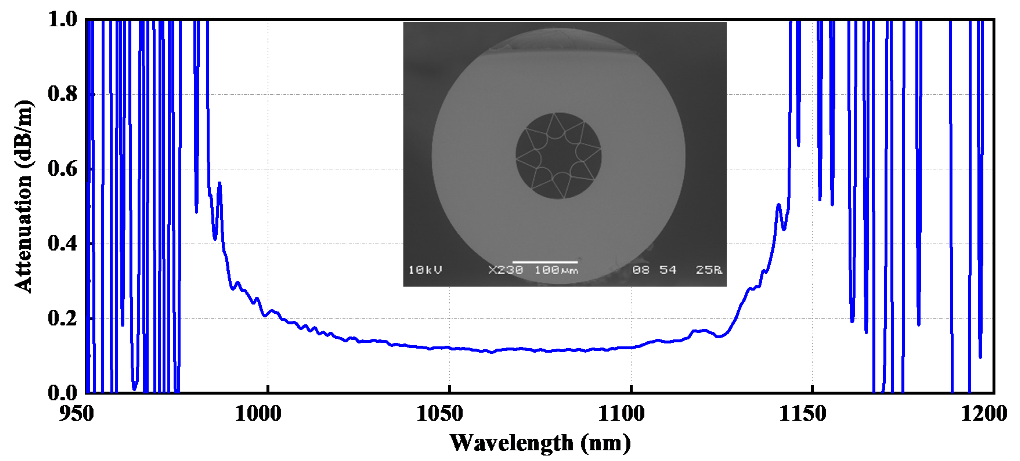
The HCF used in this paper is a kind of ice-cream, anti-resonant HCF and the structure is shown in the inset picture of Figure 1. The core is surrounded by eight ice-cream capillaries forming a negative curvature boundary, which defines the transmission band of the HCF. It has a core diameter of around 46 μm and a cladding diameter of around 280 μm. From 1000 to 1100 nm the HCF has lower transmission loss, and for the wavelength we used at 1080 nm it has a loss of around 0.12 dB/m.
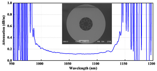
Figure 1.
The transmission loss of the ice-cream type AR-HCF used for the splicing. Inset: the cross-section electronic micrograph.
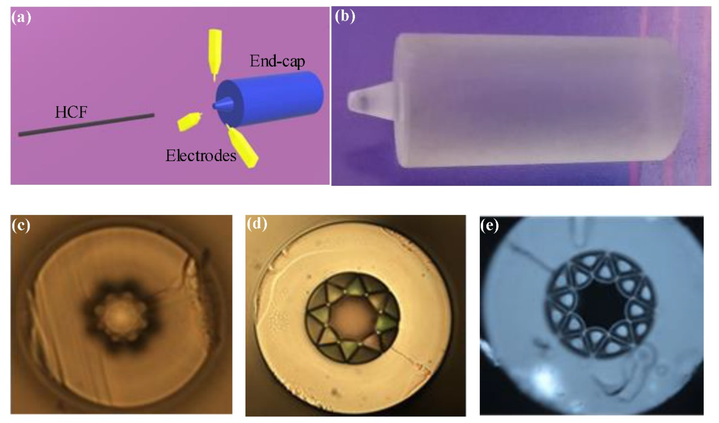
The schematic of the splicing process between the HCF and the end cap is shown in Figure 2a. Figure 2b is the picture of the end cap used for splicing. During splicing, the AR-HCF is fixed by the fiber clamp at the left side, and at the right side the end cap is fixed by a self-made clamp which is composed of three glass tubes. The splicing end of the end cap is designed as a 3 mm-long cone. The diameter of the splicing end of the cone is 1 mm, which is easy for splicing at a lower temperature, and the diameter of the larger end is 2.5 mm. The right cylinder of the end cap has a diameter of 8.2 mm and a length of 17 mm, as shown in Figure 2b. The output end is coated with an antireflection coating in the 1080 nm band. To obtain the results of the splicing, we needed to make the surfaces of the HCF and the end cap smooth. After the cutting treatment, the angle of the surface for splicing is less than 0.5°. Before splicing, the center of the HCF needed to be aligned with the center of the end cap. Then, the HCF is inserted into the end cap when the front end of the conical is heated into a molten state by the electrodes.

Figure 2.
(a) Schematic of the splicing process between the HCF and the end cap; (b) the picture of the end cap used for splicing; (c) the cross section view of the HCF after splicing at a higher temperature; (d) the cross section view of the HCF after splicing at a suitable temperature; (e) the cross section view of the HCF after splicing at a lower temperature.
Due to the hollow-core structure of the HCFs, through the splicing process, the microstructure of the HCFs will be damaged which will lead the collapse of the cladding. To control the damage of the cladding, the heating temperature of the splicing system should be controlled, and waste heat should be used to maintain the molten state through moving the heating electrode some distance away from the HCF. The temperature when the end cap is heated to the molten state is a key parameter in fabrication. Figure 2c–e show the cross section view of the HCF with splicing at different temperature conditions. Figure 2c shows the cross section after splicing when the temperature is too high, and the microstructure of the HCF is almost completely destroyed. Figure 2d shows that only the negative curvature is destroyed and the microstructure still exists when the temperature is suitable. Figure 2e shows that when the temperature is too low, the HCF and the end cap are only bonded to each other but not strongly enough. In order to achieve a better splicing effect, controlling the temperature makes sure that the cross section appears as in Figure 2d, and the deformation distance is as short as possible. After obtaining great splicing, we fabricated a nice all-fiber cavity with both ends of HCF splicing with end caps, as shown in Figure 3.
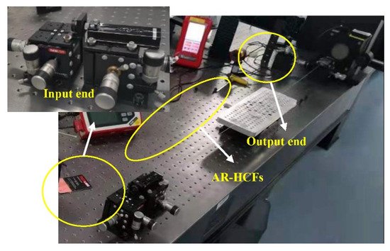
Figure 3.
Picture of the fabricated all-fiber gas cavity based on AR-HCFs and end caps in the test system.
3. Experiments
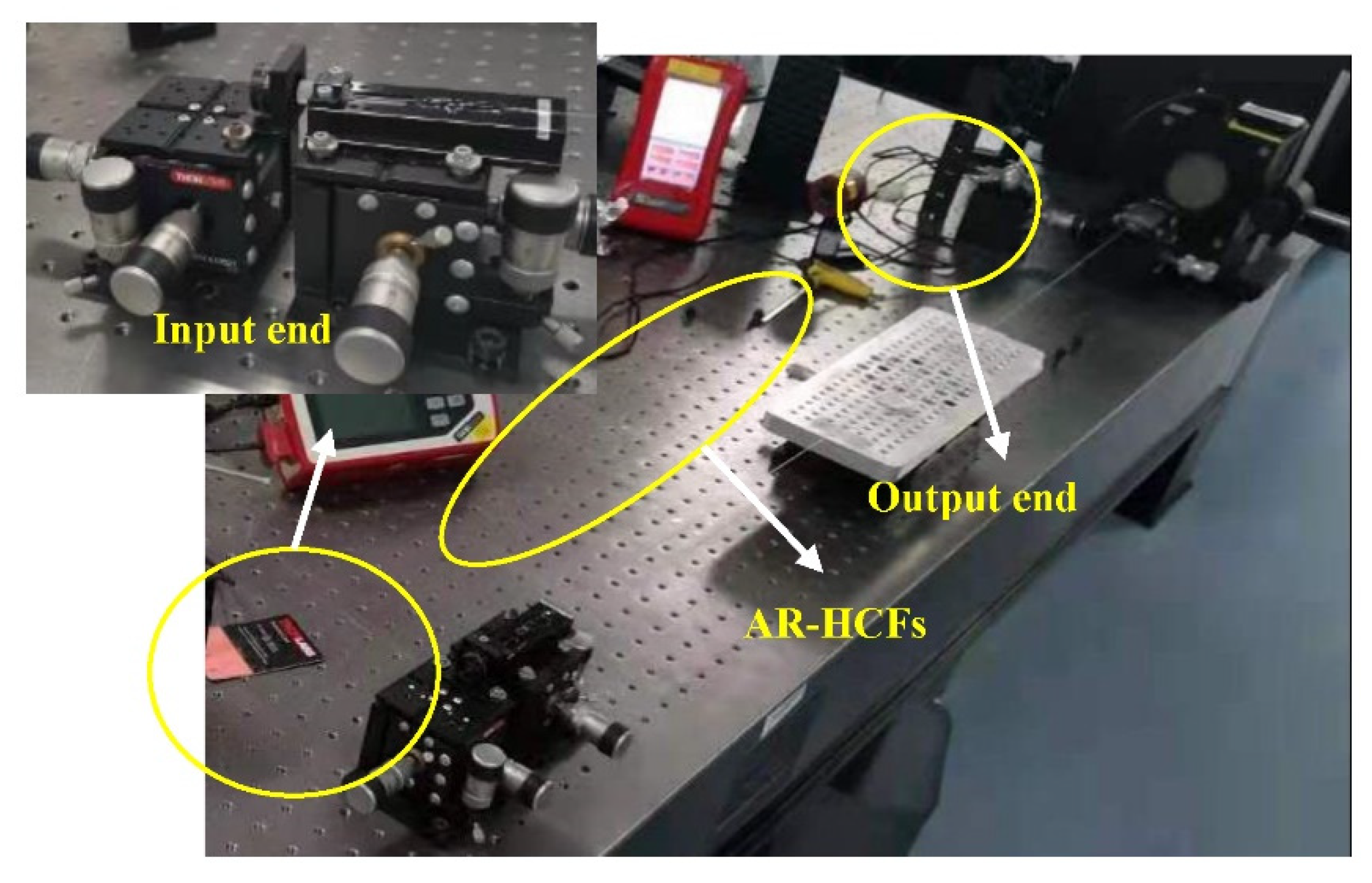
The test system of the all-fiber gas cavity is shown in Figure 4. The light source for the test is a kW-level fiber laser oscillator with a 20/400 fiber end cap. The fiber laser source has a good beam quality, as shown in Figure 4a. At the left side is the beam profile at different positions, which are both fundamental modes, and M2 is 1.13 for a and 1.21 for b when the output power is 1500 W. Two plano-convex lenses with focal lengths both of 25 mm, and two reflectors with high reflectivity at near-infrared bands are used to couple the incident light into the HCF splicing with the end cap. The core diameter of the HCF we used is 46 μm, according to the principle of mode field-matching, these two lenses are suitable for high coupling efficiency. The HCF end cap is fixed by a fixture designed by us, as shown in Figure 3. Because the anti-resonant HCF is a type of leaky fiber, an area where the cladding of the HCF and the fixture of the end cap make contact has leakage of light, which leads to heat accumulation as per the inset picture in Figure 4. This temperature is measured by a thermal imager from Fluke. The matching paste is applied evenly near the heating area, causing the temperature at this area to be significantly reduced. In order to avoid the influence of fiber bending on the measurement, the whole HCF is straightened during the experiments.
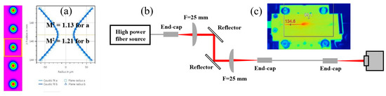
Figure 4.
(a) Measured beam profile and quality factor M2 of the fiber laser source; (b) the experimental setup of the system used to test the all-fiber gas cavity based on AR-HCFs; (c) thermal image of the HCF end cap at the input end.
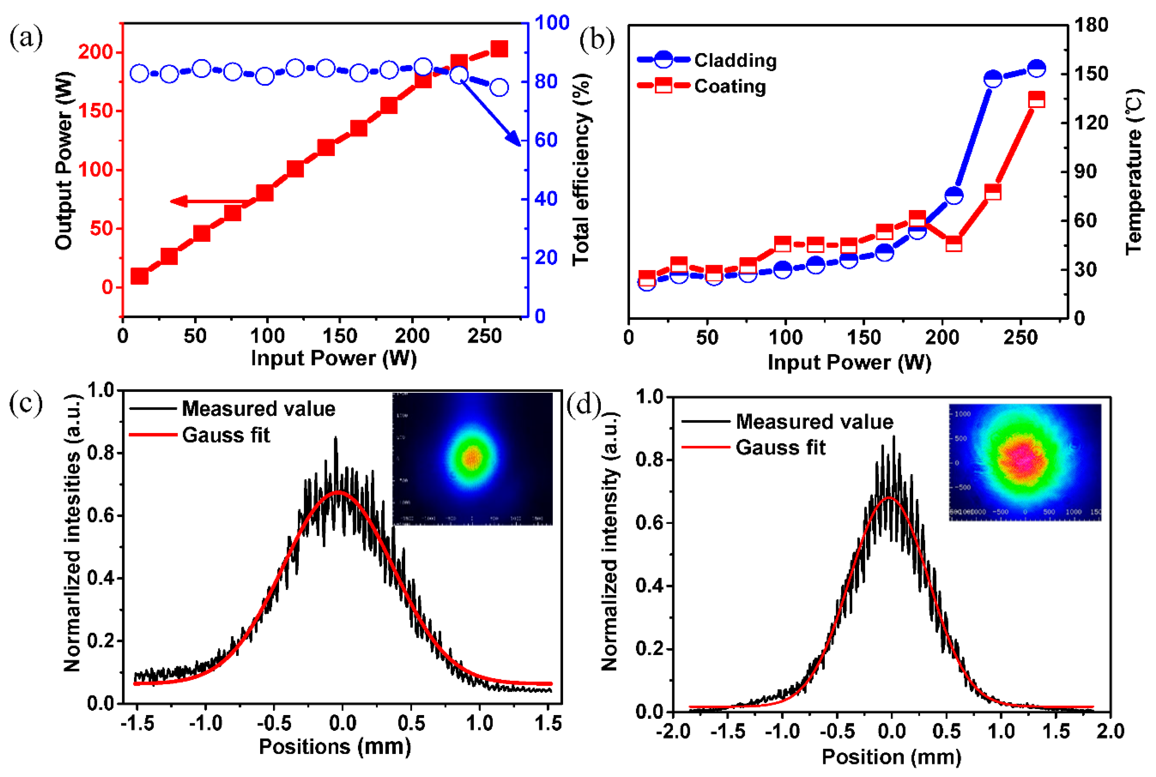
Based on the testing system above, the total efficiency from the fiber source to the output end is tested and the result is shown in Figure 5a. As the power increases, the heat accumulation of the lenses affects the efficiency, so a manual adjustment is needed to make sure the coupling efficiency is at the maximum as the power increases. After the adjustment, the efficiency stays at around 80% when the input power increases under 200 W. The total loss comes from the lenses, the reflectors, the coupling efficiency, the Fresnel reflection and the HCF itself. For the lenses, the transmission is 97.5% and the reflectivity of the reflectors is 99.5%. The transmission loss of the 1-meter-long HCF is 0.12 dB. Additionally, the Fresnel reflection is around 3.9%. According to the loss above, the coupling efficiency is estimated as 88.8%, which dominates the main loss. The output power and the monitored temperature as the input power increased is also shown. The total incident power is 260 W and the output power is 203 W. Figure 5b shows the temperature of the cladding and the coating— it is relatively moderate when the input power is below 200 W. As the input power increases above 200 W, the temperature has a sharp rise which is due to the efficiency starting to decease corresponding to the drop of the efficiency in Figure 5a. In Figure 5b, there are also two drop points in the temperature of the coating, which also correspond to the rising point in Figure 5a, which are the results of manual adjustment of the coupling efficiency. The intensity distribution in Figure 5c,d is consistent with the Gaussian distribution, which means the main energy is still the fundamental mode, and the beam profile is shown in the inset picture of Figure 5c. The beam profile varies between Figure 5c,d as the input power increases to 200 W power level. In the beam profiles, the beam from the fiber source is shown. Comparing the profiles, the edge of the beam from the end cap is not as good as that of the pump source, thus the collapse of air holes of the negative curvature of the HCF when splicing with the end cap has a slight influence on the beam quality of the output light, but the main energy is still concentrated on the center of the beam.
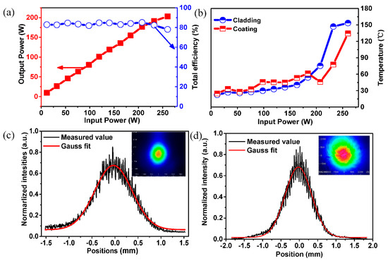
Figure 5.
(a) The total efficiency and the output power vary with the input power; (b) Measured results of the temperature of the all-fiber cavity; (c) Intensity distribution of the output beam at lower power; (d) Intensity distribution of the output beam at higher power. Inset: Beam profile of the output.
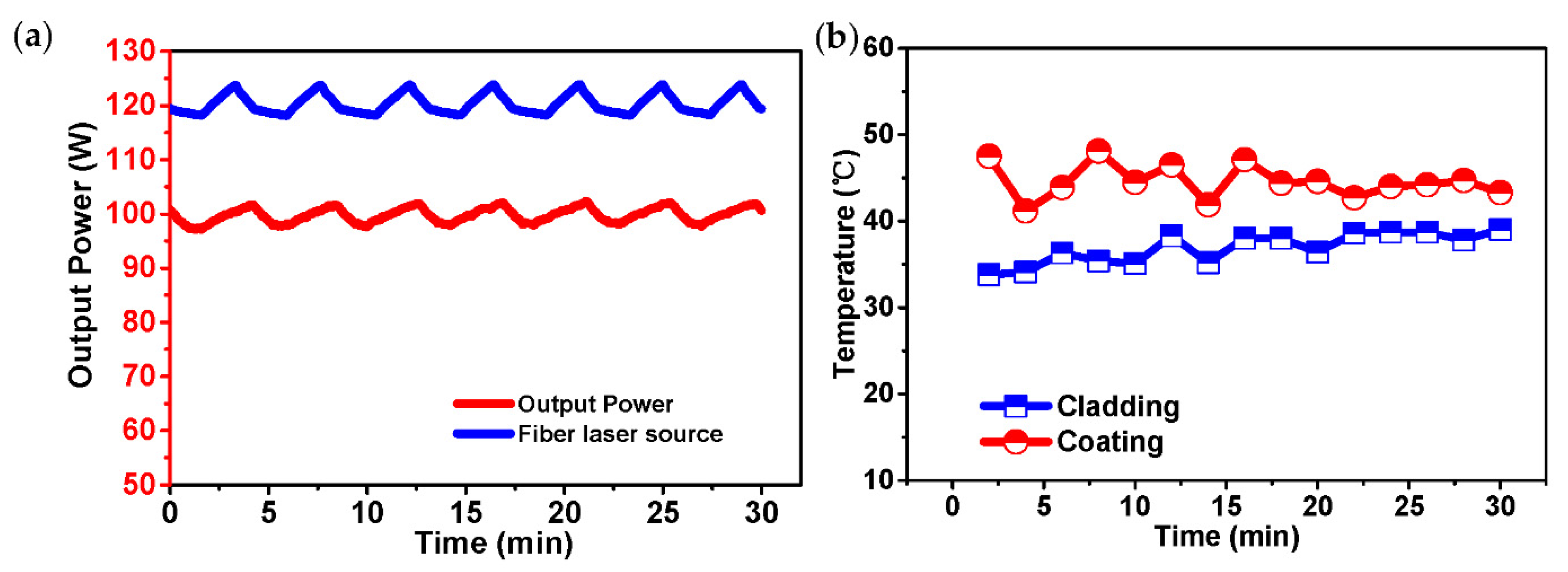
The measurements of power stability of the fiber laser source and the output power, and the temperature of the cladding and coating are carried out when the output power is 100 W, and the results are shown in Figure 6. The output power shows cyclical fluctuations near 100 W with a fluctuation the same as the power fluctuation of the fiber laser source, as Figure 6a shows. This is caused by the intermittent operation of the cooling system of the fiber laser source, during its intermittent working the power will decrease and then increase slowly as before. There are two major hot points, one is mentioned above as Figure 4c shows, the other is the front end of the coating. As Figure 6b shows, at first the temperatures of the two positions slightly fluctuate, and then the temperature of the cladding stabilizes at around 38 °C and the temperature of the coating stabilizes at around 44 °C as the time gets longer. The ice-cream AR-HCF is a type of leaky fiber, so the change in temperature is mainly due to the leakage of the input light. If the coupling efficiency does not change, the temperature will not have an obvious change. The higher temperature is caused by the leakage of light and it may be the surface temperature of the HCF, and although the temperature is higher than that of an all-fiber structure solid-core fiber laser, it is still safe to work stably.

Figure 6.
Test results of (a) power stability and (b) temperature stability of the all-fiber gas cavity at about 100 W.
4. Conclusions
We have demonstrated the first AR-HCFs-based all-fiber gas cavity based on fiber end caps. The cavity is fabricated by splicing a 1-meter-long ice-cream type of AR-HCFs with two silica end caps at both ends using a large diameter splicing system. With a high-power fiber source at 1080 nm, the characteristics of transmission efficiency, high-power capacity and stability, heat treatment, etc., were tested without active cooling. Experimental results show good stability of the all-fiber cavity at a high-power level. The maximum injecting laser power is about 260 W with a total transmission efficiency of 78.1%. Under 200 W incident power, the system can maintain a normal temperature. If a proper cooling system is designed and adopted in the future, the power capacity can be greatly enhanced. This work opens a new way for the development of high-power all-fiber FGLs.
Author Contributions
Conceptualization, Z.W. and Y.C.; methodology, W.H. and Z.Z.; validation, Z.W., M.W. and Z.C.; formal analysis, Z.W.; investigation, J.S., X.Y. and Y.C.; resources, M.W.; data curation, X.Y. and J.S.; writing—original draft preparation, J.S. and X.Y.; writing—review and editing, Z.W., Y.C. and H.L. All authors have read and agreed to the published version of the manuscript.
Funding
This research was funded by the Outstanding Youth Science Fund Project of Hunan Province Natural Science Foundation (2019JJ20023), National Natural Science Foundation of China (NSFC) (11974427, 12004431) and Postgraduate Scientific Research Innovation Project of Hunan Province (CX20200017).
Institutional Review Board Statement
Not applicable.
Informed Consent Statement
Not applicable.
Data Availability Statement
The data presented in this study are available on request from the corresponding author. The data are not publicly available due to privacy restrictions.
Acknowledgments
We thanks Jonathan C. Knight from University of Bath in UK for providing the AR-HCFs for our experiments.
Conflicts of Interest
The authors declare no conflict of interest.
References
- Pryamikov, A.D.; Biriukov, A.S.; Kosolapov, A.F.; Plotnichenko, V.G.; Semjonov, S.L.; Dianov, E.M. Demonstration of a waveguide regime for a silica hollow-core microstructured optical fiber with a negative curvature of the core boundary in the spectral region >3.5 μm. Opt. Express 2011, 19, 1441–1448. [Google Scholar] [CrossRef]
- Yu, F.; Wadsworth, W.J.; Knight, J.C. Low loss silica hollow core fibers for 3–4 μm spectral region. Opt. Express 2012, 20, 11153. [Google Scholar] [CrossRef] [PubMed] [Green Version]
- Kolyadin, A.N.; Kosolapov, A.F.; Pryamikov, A.D.; Biriukov, A.S.; Plotnichenko, V.G.; Dianov, E.M. Light transmission in negative curvature hollow core fiber in extremely high material loss region. Opt. Express 2013, 21, 9514–9519. [Google Scholar] [CrossRef] [PubMed]
- Ding, W.; Wang, Y.Y.; Gao, S.F.; Wang, M.L.; Wang, P. Recent Progress in Low-Loss Hollow-Core Anti-Resonant Fibers and Their Applications. IEEE J. Sel. Top. Quantum Electron. 2020, 264, 4400312. [Google Scholar] [CrossRef]
- Jones, A.M.; Nampoothiri, A.V.V.; Ratanavis, A.; Fiedler, T.; Rudolph, W. Mid-infrared gas filled photonic crystal fiber laser based on population inversion. Opt. Express 2011, 19, 2309–2316. [Google Scholar] [CrossRef]
- Nampoothiri, A.V.V.; Jones, A.M.; Fourcade-Dutin, C.; Mao, C.; Dadashzadeh, N.; Baumgart, B.; Wang, Y.Y.; Alharbi, M.; Bradley, T.; Campbell, N. Hollow-core Optical Fiber Gas Lasers HOFGLAS: A review. Opt. Mater. Express 2012, 2, 948. [Google Scholar] [CrossRef] [Green Version]
- Benabid, F. Stimulated Raman Scattering in Hydrogen-Filled Hollow-Core Photonic Crystal Fiber. Science 2002, 298, 399–402. [Google Scholar] [CrossRef]
- Gladyshev, A.V.; Kosolapov, A.F.; Khudyakov, M.M.; Yatsenko, Y.P.; Kolyadin, A.N.; Krylov, A.A.; Pryamikov, A.D.; Biriukov, A.S.; Likhachev, M.E.; Bufetov, I.A. 4.4 μm Raman laser based on hollow-core silica fibre. Quantum Electron. 2017, 47, 491–494. [Google Scholar] [CrossRef]
- Gladyshev, A.V.; Kosolapov, A.F.; Khudyakov, M.M.; Yatsenko, Y.; Kolyadin, A.N.; Krylov, A.A.; Pryamikov, A.; Biriukov, A.S.; Likhachev, M.E.; Bufetov, I.A. 2.9, 3.3 and 3.5 μm Raman Lasers Based on Revolver Hollow-Core Silica Fiber Filled by H2/D2 Gas Mixture. IEEE J. Sel. Top. Quantum Electron. 2018, 24, 0903008. [Google Scholar] [CrossRef]
- Li, Z.; Huang, W.; Cui, Y.; Wang, Z. Efficient mid-infrared cascade Raman source in methane-filled hollow-core fibers operating at 2.8 μm. Opt. Lett. 2018, 43, 4671–4674. [Google Scholar] [CrossRef]
- Ling, C.; Gao, S.F.; Peng, Z.G.; Wang, X.C.; Pu, W. High peak power 2.8 μm Raman laser in a methane-filled negative-curvature fiber. Opt. Express 2018, 26, 5609. [Google Scholar]
- Wei, H.; Cui, Y.; Zhixian, L.; Zhiyue, Z.; Zefeng, W. 1.56 μm and 2.86 μm Raman lasers based on gas-filled anti-resonance hollow-core fiber. Chin. Opt. Lett. 2019, 7, 71406. [Google Scholar]
- Astapovich, M.S.; Gladyshev, A.V.; Khudyakov, M.M.; Kosolapov, A.F.; Likhachev, M.E.; Bufetov, I.A. Watt-level Nanosecond 4.42-μm Raman Laser Based on Silica Fiber. IEEE Photonic Technol. Lett. 2019, 1, 78–81. [Google Scholar] [CrossRef]
- Wang, Z.; Belardi, W.; Yu, F.; Wadsworth, W.J.; Knight, J.C. Efficient diode-pumped mid-infrared emission from acetylene-filled hollow-core fiber. Opt. Express 2014, 22, 21872. [Google Scholar] [CrossRef]
- Hassan, M.R.A.; Fei, Y.; Wadsworth, W.J.; Knight, J.C. Cavity-based mid-IR fiber gas laser pumped by a diode laser. Optica 2016, 3, 218. [Google Scholar] [CrossRef]
- Xu, M.; Fei, Y.; Jonathan, K. Mid-infrared 1 W hollow-core fiber gas laser source. Opt. Lett. 2017, 42, 4055–4058. [Google Scholar] [CrossRef]
- Zhou, Z.; Ni, T.; Zhixian, L.; Wei, H.; Zefeng, W.; Wuming, W.; Weihong, H. High-power tunable mid-infrared fiber gas laser source by acetylene-filled hollow-core fibers. Opt. Express 2018, 26, 19144. [Google Scholar] [CrossRef]
- Cui, Y.; Huang, W.; Wang, Z.; Wang, M.; Zhou, Z.; Li, Z.; Gao, S.; Wang, Y.; Pu, W. 4.3 μm fiber laser in CO2 fibers. Optica 2019, 6, 951–954. [Google Scholar] [CrossRef]
- Aghbolagh, F.B.A.; Nampoothiri, V.; Debord, B.; Gerome, F.; Vincetti, L.; Benabid, F.; Rudolph, W. Mid IR hollow core fiber gas laser emitting at 4.6 um. Opt. Lett. 2019, 44, 383–386. [Google Scholar] [CrossRef] [PubMed]
- Fedorov, V.V.; Mirov, S.B.; Gallian, A.; Badikov, D.V.; Voronov, A.A. 3.77–5.05-μm tunable solid-state lasers based on Fe2+-doped ZnSe crystals operating at low and room temperatures. IEEE J. Quantum Electron. 2006, 42, 907–917. [Google Scholar] [CrossRef]
- Chang, T.; Wood, O. An optically pumped CO2 laser. IEEE J. Quantum Electron. 1972, 8, 598. [Google Scholar] [CrossRef]
- Vurgaftman, I.; Meyer, J.R. Analysis of limitations to wallplug efficiency and output power for quantum cascade lasers. J. Appl. Phys. 2006, 99, 123101–123108. [Google Scholar] [CrossRef]
- Maes, F.; Fortin, V.; Bernier, M.; Vallée, R. 5.6 W monolithic fiber laser at 3.55 μm. Opt. Lett. 2017, 42, 2054. [Google Scholar] [CrossRef] [PubMed]
- Maes, F.; Fortin, V.; Poulain, S.; Poulain, M.; Vallée, R. Room-temperature fiber laser at 3.92 μm. Optica 2018, 5, 761. [Google Scholar] [CrossRef]
- Fortin, V.; Jobin, F.; Larose, M.; Bernier, M.; Vallée, R. 10-W-level monolithic dysprosium-doped fiber laser at 3.24 μm. Opt. Lett. 2019, 44, 491–494. [Google Scholar] [CrossRef]
- Drich, S.H.; Rothhardt, J.; Demmler, S.; Tschernajew, M.; Hoffmann, A.; Krebs, M.; Liem, A.; Vries, O.D.; Pl Tner, M.; Fabian, S. Scalability of components for kW-level average power few-cycle lasers. Appl. Opt. 2016, 55, 1636–1640. [Google Scholar]
- Yu, F.; Wu, D.; Wang, Y.; Li, Q.; Chen, S. Delivery of CW laser power up to 300 watts at 1 μm by uncooled low-loss antiresonant hollow-core fiber. Opt. Express 2020, 29, 1492–1501. [Google Scholar]

Publisher’s Note: MDPI stays neutral with regard to jurisdictional claims in published maps and institutional affiliations. |
© 2021 by the authors. Licensee MDPI, Basel, Switzerland. This article is an open access article distributed under the terms and conditions of the Creative Commons Attribution (CC BY) license (https://creativecommons.org/licenses/by/4.0/).