1. Introduction
The CO
laser was invented in 1964, at the very beginning of the laser era [
1] and almost immediately became one of the most popular lasers for science and industry. This was due to the high efficiency, robustness, and scalability of the transverse-electric-discharge pumped systems in which an atmospheric-pressure mixture of carbon dioxide, nitrogen, and helium is used as an active medium. By the 1980s, the CO
lasers had become very mature machines [
2] and dominated the laser market. With the advancement of other types of lasers, the number of options available for the architects of laser-based systems has increased, resulting in a gradual decrease of the share of the CO
lasers. Considering that modern solid-state lasers are usually more compact and easier to maintain than the electric-discharge gas lasers, the niche for the CO
lasers should be expected to continue to shrink in the coming years. However, a unique wavelength in the long-wave infrared range that is not reachable by the powerful solid-state lasers ensures that the high-power CO
lasers will continue to play an important role in science and technology for a long time.
One important industrial application of a CO
laser that emerged recently is the extreme ultraviolet (EUV) light sources for lithography machines with nanometer-scale resolution. In these sources, a focused laser pulse hits a tin droplet, producing a plasma that emits a 13.5 nm EUV light. A powerful CO
laser is used in this scheme because its 10.6 µm wavelength provides a superior conversion efficiency compared to the near-IR (
µm) wavelength of solid-state (e.g., Nd:YAG) lasers [
3,
4].
Modern science is looking into the behavior of the matter in very strong fields, thus calling for ultra-intense lasers. A growing interest in LWIR lasers is motivated by the substantially different regimes of the interaction between the charged particles and the oscillating electromagnetic field that can be achieved using a relatively low frequency of the LWIR light because of an inverse-quadratic scaling of the ponderomotive force with the field frequency. The ponderomotive effect of focusing a picosecond, = 10 µm, LWIR pulse of several joules of energy into a several-wavelength, diffraction-limited spot size resulting in an intensity of – W/cm is equivalent to focusing a 1 µm near-IR laser to – W/cm. In both cases, the normalized field strength parameter will be the same ( = 1–3), where e and m are the electron charge and mass, respectively; c is the speed of light; E is the laser’s electric field; and is the laser frequency.
In this paper, we discuss the state of the art of ultra-short-pulse, multi-terawatt LWIR lasers and the present research and development efforts toward even shorter and more powerful pulses and more robust laser systems. First, however, we will present a brief historical overview of the relevant technologies.
2. Historical Overview of Ultra-Short-Pulse High-Peak-Power CO Laser Technology
2.1. Elements of High-Peak-Power Lasers
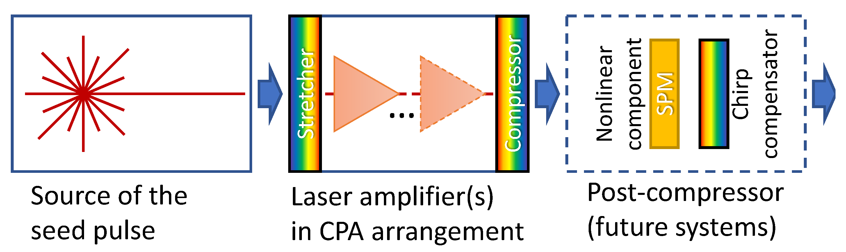
A general scheme of a high-peak-power laser is shown in
Figure 1.
A low-energy ultra-short pulse is produced by a seed laser. This pulse is then amplified in a series of laser amplifiers that employ a chirped-pulse amplification (CPA) scheme [
5] to avoid nonlinear interaction between the optical field of the pulse and the materials of the amplifiers by stretching the pulse before the amplification and re-compressing it after the amplification. The minimum duration of a pulse achieved at this stage is defined by the bandwidth of the amplifier’s gain medium. The pulse can be further compressed with a simultaneous increase of its peak power using a post-compression technique. In a typical post-compressor, a spectrum broadening accompanied by a chirp is achieved via self-phase modulation (SPM), a nonlinear optical phenomenon associated with the Kerr effect. The chirp is then compensated, e.g., by a chirping mirror, resulting in a shorter pulse. The post-compression is presently the subject of multiple research and development efforts worldwide; its reliable operation in a production system has yet to be demonstrated [
6].
In the following paragraphs, we describe the timeline of the research and development efforts that allowed a recent implementation of an ultra-short-pulse, high-peak-power LWIR laser based on the general scheme of
Figure 1.
2.2. 1970s and 1980s: First Steps
The first feasible method of producing a picosecond pulse at a CO
laser wavelength was developed in the mid-1970s and involved slicing a tiny portion from a long pulse of a conventional CO
laser (typically a few hundred nanoseconds long) [
7]. This was achieved using a semiconductor switch—a plate of a semiconductor material, e.g., germanium, which is normally transparent for the LWIR light. The plate is illuminated by a pulse of a visible or near-infrared (VNIR) light with a photon energy exceeding the band gap of the semiconductor. This excites some of the electrons into the conduction band, causing the semiconductor to absorb or, if the density of the free electrons is sufficiently high, reflect in the LWIR. A set-up with two semiconductor switches controlled by short VNIR laser pulses allows truncating both the leading and the trailing parts of the CO
laser pulse. LWIR pulses as short as 130 fs were reportedly produced by this technique [
8].
The next step toward high peak power was the deployment of multi-atmosphere CO
laser amplifiers to amplify ultra-short LWIR pulses [
9]. The gain spectrum of a conventional atmospheric-pressure CO
laser comprises four branches conventionally denoted as
,
,
, and
. Each branch is split into a few dozen narrow, periodically spaced peaks, as shown in
Figure 2a. These peaks correspond to transitions between rotational sub-levels of two pairs of vibrational levels (with a common upper level) supporting lasing in the excited CO
molecules.
An attempt to amplify an ultra-short pulse with a bandwidth covering several rotational lines in such a laser would result in a corresponding modulation of the amplified spectrum. The modulation of the spectrum results in the splitting of the pulse into a train of sub-pulses. The length of the train is inversely proportional to the width of an individual spectral line, and the distance between the sub-pulses is inversely proportional to the separation between the spectral lines. The width of the spectral lines in the amplified spectrum becomes smaller at higher amplification (and eventually becomes smaller than the width of the lines in the gain spectrum) due to the effect known as gain narrowing. Thus, the length of the train increases with the increase in amplification.
The effect of pulse splitting is reduced in a multi-atmosphere amplifier due to the collisional broadening and partial overlapping of the spectral lines. Although the modulation of the gain spectrum is not completely eliminated at a ∼10 bar maximum practical pressure of a discharge-pumped CO
amplifier (
Figure 2b), the length of the pulse train can be reduced substantially, typically to half a dozen sub-pulses. 10–20 mJ energy in the strongest sub-pulse was reported in [
9] when a 3 ps seed pulse was amplified in a ∼10 bar regenerative CO
amplifier.
In the same work [
9], the post-compression of an amplified pulse to <600 fs was demonstrated by allowing the pulse to propagate through the amplifier a few more times after reaching maximum energy. The compression was explained by self-phase modulation in the partially ionized active medium followed by the chirp compensation by the negative group velocity dispersion in the NaCl windows of the amplifier vessel.
Even though it was not immediately applied to the amplification of ultra-short LWIR pulses, progress was achieved in demonstrating very high-pressure (up to 33 bar) optically pumped CO
amplifiers [
10,
11] and the amplifiers with isotopically enriched carbon dioxide [
12]. In both cases, a broad gain spectrum without a rotational structure can be achieved. The suggested use for these systems was as the sources of continuously tunable LWIR light. Chemical HF, DF, and HBr lasers were used for optical pumping; however, it was realized that solid-state lasers are potentially more attractive as pump sources and various pumping schemes were suggested [
13] but not implemented at the time, most likely due to the unavailability of suitable high-energy lasers.
Construction of the Antares CO
laser facility at Los Alamos National Laboratory for an inertial confinement fusion project [
14] (commissioned in 1984) and a similar but less energetic laser, LEKKO VIII, at the Institute of Laser Engineering of Osaka University [
15] (commissioned in 1981) were probably the culmination of the first two decades of the development of CO
lasers. The Antares laser produced up to a total of 30 kJ of energy in 24 beams combined on the target. Pulse duration was ∼1 ns, implying a near 30 TW total peak power. The laser operated at several rotational lines for efficient power extraction from the amplifiers. However, because of a relatively long optimum pulse duration required for the inertial confinement, the rotational structure of the spectrum did not represent a problem and a relatively low, 1.6 bar pressure of active gas was used in the amplifiers. The Antares project was terminated in 1985 because it was found that lasers with shorter wavelengths had a better potential for achieving fusion (for comparison, the third harmonics of an Nd:glass laser at 351 nm is presently used at the National Ignition Facility). Even though the picosecond regime was not used in the Antares laser, theoretical models and technical solutions developed during this effort became important building blocks for future ultra-short-pulse terawatt CO
lasers.
2.3. 1990s, 2000s, and 2010s: Terawatts and Picoseconds
The invention of chirped-pulse amplification in 1985 [
5] eliminated a major bottleneck limiting the energy to which an ultra-short pulse could be amplified in a solid-state laser amplifier. At the same time, new types of solid-state lasers with very broad gain spectra suitable for generation and amplification of femtosecond pulses had emerged, most noticeably the Ti:Sapphire laser first demonstrated in 1982 [
16]. This resulted in redirecting the focus of many research and development efforts aimed at strong-field lasers from gas to solid-state active media. Admittedly, this allowed fast, steady progress in the field of high-peak-power lasers, leading to the first demonstration of a petawatt peak power in 1996 [
17,
18] and the present-day race toward exawatt power [
6].
The development of short-pulse high-power CO
lasers was, however, continued by several research groups, both theoretically and experimentally; two systems eventually achieved multi-terawatt peak power in picosecond LWIR pulses (three orders of magnitude shorter pulse duration compared to the Antares CO
laser). Both these lasers were built in the United States with the main purpose of studying the potential of different schemes of laser particle acceleration driven by LWIR laser pulses. Fifteen TW in the strongest sub-pulse of a 3–5-pulse train with 3 ps pulse duration was demonstrated at the Neptune facility of UCLA’s Plasma Accelerator Group [
19]. Five TW peak power in a single 2 ps pulse was recently achieved by the CO
laser at Brookhaven’s Accelerator Test Facility (ATF) [
20].
Initially, short seed pulses for these lasers were generated by a traditional slicing technique; this was later improved by the introduction of a new high-contrast scheme for fast pulse switching based on the optical Kerr effect [
21]. More recently, compact solid-state sources of (sub-)picosecond LWIR pulses became available and replaced the slicing setups in the front ends of the high-peak-power LWIR lasers. One such commercial scheme involves a difference frequency generation (DFG) between the signal and idler waves at the output of an optical parametric amplifier (OPA) pumped by a Ti:Sapphire laser (this seed system is described in Section 2.4 of [
22]).
High-pressure (∼10 bar) CO
laser amplifiers were developed with active volumes up to 85 × 100 × 1000 mm
[
23,
24], allowing amplification of picosecond pulses to multi-joule energies. Residual rotational modulation that is normally present in these amplifiers can be eliminated by using isotopically enriched carbon dioxide [
25]. In a properly optimized mixed-isotope gain medium, the gain spectra of different isotopologues of CO
overlap, resulting in a spectrum with a smooth, broad peak that corresponds to the
branch centered at 9.2 µm, as shown in
Figure 3.
The bandwidth of the 9.2 µm spectral peak of the mixed-isotope active medium is sufficient for the amplification of a transform-limited 2 ps pulse from a microjoule- to a multi-joule- energy [
20]. This peak was also found to be considerably stronger compared to the strongest peak of the non-enriched carbon dioxide (
peak at 10.3 µm in
Figure 2b), in agreement with the spectroscopic data that has only recently become available [
26].
Implementation of a CPA scheme for the first time in a gas laser [
20,
27] represents the most recent practical achievement in the field of high-peak-power LWIR lasers and enables further progress toward shorter pulse durations and higher peak powers.
2.4. 2020s and Beyond: Present-Day R&D and Perspectives
The ongoing research and development can be roughly categorized as follows:
Reduction of the pulse duration at the output of the amplifiers by more efficient use of their gain spectrum, e.g., amplification of a ∼0.5 ps pulse using both and bands.
Post-compression of the output pulse beyond the limit imposed by the bandwidth of the gain spectrum, e.g., via self-phase modulation. The aim here is to achieve a pulse duration on the order of 100 fs corresponding to a few optical cycles at LWIR wavelengths.
Exploration of the potential of optical pumping for increasing efficiency, repetition rate, and robustness of the high-pressure CO amplifiers.
Important supporting activities include the study of the responses of infrared optical materials on strong LWIR optical fields and deployment of vacuum systems for the delivery of the increasing peak powers to the experiment locations.
Present-day high-peak-power LWIR lasers are relatively small machines (roughly the size of a large room) compared to some near-IR petawatt+ systems. Construction of LWIR systems scaled up to peak power levels on the order of 100 TW and beyond is thus possible depending on the demand in the scientific community. For example, coherent beam combining of the outputs of several amplifiers can be considered a relatively straightforward brute-force solution.
3. State of the Art
The LWIR laser system at ATF incorporates most of the recently developed elements: a solid-state front-end, mixed-isotope power amplifiers, and a CPA scheme. We will thus use this system to illustrate the state of the art in the field. We will then briefly discuss the distinctive features of other existing and under-development high-peak-power LWIR lasers.
The schematics of the ATF’s LWIR laser are shown in
Figure 4 in the configuration used for the demonstration of 2 ps, 5 TW pulses. A detailed description of this laser can be found in [
20]. Here, we give a very brief description and discuss the most important performance parameters.
A femtosecond seed pulse at 9.2 µm is generated in a commercial setup comprising an Erbium oscillator, Ti:Sapphire laser amplifier, and an OPA-based frequency conversion device.
A series of two high-pressure, mixed-isotope CO amplifiers is used to amplify the pulse to up to 20 J. The regenerative amplifier has a 10-millimeter clear aperture and operates with a 10 bar active medium enriched with 43% of Oxygen-18. The inter-electrode distance defining the clear aperture of the final amplifier is 85 mm, the gas pressure is 8.25 bar, and the Oxygen-18 content is 47%. The optimum isotopic compositions of CO in the amplifiers is defined by the Einstein coefficients of the CO isotopologues and the partial saturation regime of operation of the final amplifier resulting in a faster depletion of excitation of O-containing molecules compared to the natural CO isotopologue.
The CPA apparatus comprises a Martinez stretcher and a 4-grating Treacy type compressor. Both devices use 100 lines/mm gold-coated plane-ruled gratings and provide a chirp of ∼3.5 GHz/ps that corresponds to stretching of a 2 ps pulse to 70 ps. The measured 70% transmittance of the compressor is similar to that of near-IR systems.
The output spectrum and temporal pulse profile are shown in
Figure 5a,b, respectively.
The strong (compared to the gain spectrum) spectral modulation of the amplified pulse and its relatively narrow bandwidth are due to a very high gross amplification in the system. The high amplification is needed to raise the energy of the pulse from microjoules to tens of joules and to compensate optical losses in the system.
The maximum repetition rate of the ATF’s LWIR laser is 0.05 Hz (one shot in 20 s).
ATF’s high-peak power LWIR laser is presently the only laser of this class that employs a mixed-isotope CO active medium and a chirped-pulse amplification scheme.
The multi-terawatt CO
laser at UCLA [
19] uses a moderate-pressure, 2.5 bar final amplifier. This allows a substantially larger clear aperture (200 mm) but results in stronger modulation of the gain spectrum. This is partially compensated by using a helium-free active medium (collision of a CO
molecule with another CO
or an N
molecule is more efficient for line broadening than a collision with He). For further reduction of the spectral modulation, UCLA’s final amplifier relies on the power broadening of spectral lines in the saturation regime of operation.
A 1-terawatt LWIR laser currently under development at the Naval Research Laboratory [
28] will have a relatively high 1 Hz repetition rate and will use two commercial CO
amplifiers with a 20 × 20 mm
cross-section of the discharge volume [
24]. The final amplifier will be arranged in an unstable-cavity configuration.
4. Ongoing Research and Development
4.1. Femtosecond Pulses
Several ongoing research and development programs investigate the potential for further increasing the peak power of LWIR lasers and bringing it into the range of tens of terawatts. To illustrate the main directions of these efforts, we consider the possibility of reducing the pulse duration in a system based on the ATF’s high-pressure, mixed-isotope CO final amplifier. One approach presently under investigation relies on a fuller use of the amplifier’s gain spectrum, thus reducing the pulse duration at the output of the compressor. Another approach is a post-compression of the output pulse to a duration below the limit imposed by the bandwidth of the gain spectrum.
4.1.1. Better Use of the Gain Bandwidth
The shortest terawatt pulse demonstrated so far has a 2 ps duration and is produced by amplification of a microjoule seed pulse in the
branch of the gain spectrum of high-pressure, mixed-isotope CO
amplifiers (
Figure 5). Despite a broad spectrum of the seed pulse completely covering the
branch, the spectrum of the pulse after amplification is relatively narrow because of a strong gain narrowing in the two-amplifier laser system. This strong gain narrowing is due to a very high, ∼10
gross amplification that comprises a ∼10
net amplification, elevating the energy of a microjoule seed pulse to tens of joules and a ∼10
amplification spent on compensating the optical losses in the system.
Most of the net amplification and almost all the optical losses occur in the first of the two amplifiers operating in a regenerative configuration with inherently high injection and round-trip losses. Thus, if a short seed pulse with an energy sufficient for seeding the multi-pass final amplifier directly were available, the gross amplification could be kept at a relatively low
–
level. This would not only have resulted in a smaller gain narrowing, but also allowed the use of the bandwidth of two spectral branches:
centered at 9.2 µm and
at 9.4 µm (
Figure 6).
Numerical modeling shows that a sub-picosecond seed pulse with ∼10 mJ of energy is needed to achieve the energy level of the present two-amplifier system in a single amplifier. The optimal duration of the seed pulse before the stretcher is ∼300 fs and the optimal central wavelength is 10.3 µm. The output pulse after compression comprises a 500 fs leading peak containing ∼75% of the energy followed by a small secondary peak at a 1 ps delay. The four-fold shortening of the pulse compared to the present configuration results in a four-fold increase in the peak power: from 5 TW to up to 20 TW if the system is fully optimized.
The positive chirp of the pulse plays an important role in the amplification in this regime. Because of the chirp, the energy is first extracted from the active medium by the long-wave head of the pulse through the relatively weak transitions in the
branch. At high intensity, this results in a partial depletion of the inversion of population and a reduction of the amplification of the trailing part of the pulse on the
branch. This way, the effect of the higher small-signal gain of the
branch compared to the
branch is reduced, allowing for balanced energy distribution in the spectrum of the output pulse (
Figure 6a).
A laser system for generating a millijoule LWIR seed pulse is presently under development. One proposed configuration involves a Raman conversion of a high-energy chirped near-IR pulse in a solid material followed by a difference frequency generation between the Raman-shifted and the non-converted frequencies in a wide-bandgap nonlinear crystal. The output of this process is an LWIR pulse with the frequency equal to the Raman shift and the same chirp and bandwidth as the original near-IR pulse without losses to two-photon absorption. A potential material for the Raman converter is calcite (CaCO); it has a high cross-section Raman peak at 1086 cm (9.2 µm), which is very close to the optimum for seeding the CO amplifier.
4.1.2. Post-Compression
Pulse post-compression is usually achieved using a two-element scheme, as shown in
Figure 1. The high-intensity pulse interacts with the first element non-linearly, introducing a chirp via self-phase modulation; at this stage, the bandwidth of the pulse’s spectrum increases while its duration remains the same. The second element linearly removes the chirp, thus compressing the pulse and not affecting its spectrum.
The two processes, nonlinear chirping and linear de-chirping (compression), can occur simultaneously in a single optical element. This happens when the material of the nonlinear element has a suitable group velocity dispersion (GVD) that compensates for the chirp introduced by the SPM in the same element. Luckily, at least two materials commonly used in LWIR optical systems, NaCl and KCl, have a suitable combination of a positive nonlinear refractive index and a negative GVD to allow a single-element post-compression of ultra-short pulses at a wavelength of a CO laser.
The effect of the negative GVD in NaCl windows of a laser amplifier resulting in the compression of a positively chirped pulse was observed in the early days of the high-peak-power CO
lasers [
9]. More recently, a post-compression scheme where simultaneous nonlinear chirping and linear de-chirping in NaCl are used for the compression of picosecond CO
laser pulses was suggested [
29]. In the proposed configuration, four NaCl plates with a total thickness of 190 mm are used to compress a 2.5 ps pulse at 10.3 µm by roughly a factor of four. The plates are separated by spatial filters to avoid the effect of small-scale self-focusing that otherwise causes formation of micro-filaments that damage the material. In the case of a 500 fs input pulse, the thickness of an NaCl element required for optimal pulse compression is substantially reduced. Calculations performed for the pulse expected at the output of the single-amplifier LWIR laser discussed in the previous section indicate that for an energy fluence of 500 mJ/cm
, which NaCl should be able to withstand [
9], only a 22 mm thick NaCl plate is needed to achieve the best compression. The results of these calculations are shown in
Figure 7.
Assuming a flat-top input beam and neglecting losses, we obtained compression of the pulse to a 50 fs duration (less than two optical cycles at 9.3 µm) with a seven-fold increase of the peak power. In these idealized approximations, the output peak power of a 14 J pulse reaches 140 TW. Intensity variation in the beam, optical losses, and other imperfections in a real laser may result in a substantially smaller increase of the peak intensity in the post-compressor. Nevertheless, it seems reasonable to expect that at least a peak power exceeding the 30 TW record set by the Antares project for an LWIR wavelength in the 1980s can be achieved, in a four orders of magnitude shorter pulse.
4.1.3. Note on Scalability
Existing or planned terawatt-class LWIR lasers are trailing in peak power the modern near-IR laser facilities operating at a petawatt+ peak power. This leads to the question of how high the peak power the present or under-development LWIR laser technology can be scaled up.
We believe that in the foreseeable future, amplification in high-pressure CO
amplifiers will remain the only option for generating ultrahigh-peak-power LWIR laser pulses. The main factors limiting our ability to increase the power of the amplifiers by increasing the size of the active medium are (1) difficulty in increasing the inter-electrode distance beyond ∼10 cm while maintaining the uniformity of the high-voltage discharge, and (2) limited aperture of amplifier’s output window that can withstand the high pressure of the gaseous active medium at a reasonable thickness of the window material. Based on our experience with high-pressure CO
amplifiers, we estimate a realistically achievable output energy of a single-beam system as 100–200 J, a factor of 5–10 higher compared to the ATF’s laser. For a 500 fs pulse without post-compression (
Figure 6), this corresponds to a 100–200 TW peak power. 0.5 PW can then be considered an ambitious but reachable goal for a post-compressor design.
A further increase of the peak power to a petawatt level and beyond can be possible by combining the outputs of multiple amplifiers: either intersecting the beams in the interaction point or using a coherent beam combining scheme. We note that because the coherent beam combining relies on accurate control of the phase shift between the beams, its practical implementation for long-wave infrared can be less challenging compared to near-IR beams with ten times shorter wavelength.
4.2. Optical Pumping
The vibrational excitation of CO molecules by electron impact in electric discharge (either directly or via N molecules with subsequent collisional energy transfer) is the common method of establishing a population inversion in the active medium of CO lasers. This technique works especially well in atmospheric-pressure continuous-wave systems that typically achieve a wall-plug efficiency ≥10%. Scaling up the discharge-pumping scheme to high-pressure, large-aperture amplifiers is, however, technically challenging because of the increase of the optimal voltage in direct proportion to the pressure and the inter-electrode distance. Gas pressure and CO concentration in the discharge-pumped lasers are limited by the requirements for the stability, homogeneity, and reproducibility of the high-voltage discharge. Various schemes of optical pumping that are potentially more scalable and can provide homogeneous and reproducible deposition of the pump energy in the active gas are thus being studied.
The most attractive scheme for optical excitation of a CO
laser is the direct pumping of the upper laser level through an absorption band centered at ∼4.3 µm (
Figure 8).
An alternative scheme is pumping at ∼2.8 µm through a combinational vibration. In this case, a pumping photon supplies one quanta of energy for both the upper and the lower laser levels; the energy from the lower level is then quickly dissipated through collisions with He (see the diagram in the insert in
Figure 8).
Fast progress in solid-state mid-wave infrared lasers (see, for example, [
30]) enables near-term deployment of efficient high-energy sources suitable for the optical pumping of CO
amplifiers. A promising source for optical pumping at 4.3 µm is a Fe:ZnSe laser [
31,
32]. The 2.8 µm transition can be pumped by an Er:YSGG laser [
33] or by GaSb diode lasers [
34]. Diode pumping promises high wall-plug efficiency and enables an elegant configuration where diode modules are located inside the gas vessel immediately surrounding the active volume. Achieving high energy density in short pulses, however, represents a challenge that may require pushing the corresponding technology beyond the present state of the art.
To demonstrate the requirements for the pump lasers, we consider a 10-atmosphere CO
amplifier with a 1 bar CO
and 9 bar He gas mixture. To achieve a typical 2%/cm gain, we must excite ∼7% of the CO
molecules, or 1.9 × 10
cm
. Considering that one absorbed photon excites one molecule, we obtain 87 mJ/cm
and 134 mJ/cm
at 4.3 µm and 2.8 µm, respectively, for the minimum density of the deposited energy. The energy deposition requirement increases with the duration of the pumping pulse because of the collisional relaxation. At a 300 K gas temperature, the relaxation time
is defined as [
35]:
where
is expressed in microseconds and pressures
of the components of the gas mixture are expressed in bars. For the 1 bar CO
, 9 bar He mixture, Equation (
1) gives
µs. We can now calculate the energy deposition required to achieve the 2%/cm gain as a function of the pulse duration. The calculation results are shown in
Figure 9a.
According to
Figure 9a, to minimize the loss of the pump energy through the vibrational relaxation, the duration of the pumping pulse must be within a few hundreds nanoseconds—a relatively relaxed requirement if a Q-switched laser system is used for optical pumping. In the case of pumping by laser diodes that usually operate more efficiently in a long-pulse regime, it may be preferable to sacrifice some
energy in favor of reducing the requirement on the pump
power.
Figure 9b shows the power deposition requirement as a function of pulse duration. For the gas mixture considered in this example, a reasonable balance between the relaxation losses and the required pump power is achieved at a pumping pulse duration of ∼1–2 µs. Total pump energy on the order of a kJ will be needed to optically pump a typical several-liter active volume of a final CO
amplifier.
5. Conclusions
We presented a brief overview of the history and the state of the art of ultra-short-pulse, high-peak-power long-wave infrared lasers and discussed perspectives for their future development and scaling up to a petawatt-level peak power.
Author Contributions
Conceptualization, M.N.P., I.V.P.; software, M.N.P.; writing—original draft preparation, M.N.P.; writing—review and editing, I.V.P., M.B., R.K., N.V.-N., M.A.P.; project administration, N.V.-N., M.A.P.; funding acquisition, M.N.P., I.V.P., M.A.P. All authors have read and agreed to the published version of the manuscript.
Funding
U.S. Department of Energy (DE-SC0012704); Department of Energy (DOE) Accelerator Stewardship Program grant, B&R #KA2601020.
Institutional Review Board Statement
Not applicable.
Informed Consent Statement
Not applicable.
Conflicts of Interest
The authors declare no conflict of interest.
Abbreviations
The following abbreviations are used in this manuscript:
| ATF | Accelerator Test Facility |
| CPA | Chirped-pulse amplification |
| DFG | Difference frequency generation |
| EUV | Extreme ultraviolet |
| GVD | Group velocity dispersion |
| LWIR | Long-wave infrared |
| OPA | Optical parametric amplifier |
| SPM | Self-phase modulation |
| UCLA | University of California, Los Angeles |
| VNIR | Visible and near-infrared |
References
- Patel, C.K.N. Continuous-wave laser action on vibrational-rotational transitions of CO2. Phys. Rev. 1964, 136, A1187–A1193. [Google Scholar] [CrossRef]
- Witteman, W.J. The CO2 Laser; Springer: Berlin/Heidelberg, Germany, 1987. [Google Scholar]
- Hassanein, A.; Sizyuk, V.; Harilal, S.S.; Sizyuk, T. Analysis, simulation, and experimental studies of YAG and CO2 laser-produced plasma for EUV lithography sources. In Extreme Ultraviolet (EUV) Lithography; Fontaine, B.M.L., Ed.; SPIE: Bellingham, WA, USA, 2010. [Google Scholar] [CrossRef]
- Nowak, K.; Ohta, T.; Suganuma, T.; Fujimoto, J.; Mizoguchi, H.; Sumitani, A.; Endo, A. CO2 laser drives extreme ultraviolet nano-lithography—Second life of mature laser technology. Opto-Electron. Rev. 2013, 21. [Google Scholar] [CrossRef]
- Strickland, D.; Mourou, G. Compression of amplified chirped optical pulses. Opt. Commun. 1985, 56, 219–221. [Google Scholar] [CrossRef]
- Danson, C.N.; Haefner, C.; Bromage, J.; Butcher, T.; Chanteloup, J.C.F.; Chowdhury, E.A.; Galvanauskas, A.; Gizzi, L.A.; Hein, J.; Hillier, D.I.; et al. Petawatt and exawatt class lasers worldwide. High Power Laser Sci. Eng. 2019, 7. [Google Scholar] [CrossRef]
- Alcock, A.J.; Corkum, P.B. Ultra-fast switching of infrared radiation by laser-produced carriers in semiconductors. Can. J. Phys. 1979, 57, 1280–1290. [Google Scholar] [CrossRef]
- Rolland, C.; Corkum, P.B. Generation of 130-fsec midinfrared pulses. J. Opt. Soc. Am. B 1986, 3, 1625. [Google Scholar] [CrossRef]
- Corkum, P. Amplification of picosecond 10 µm pulses in multiatmosphere CO2 lasers. IEEE J. Quantum Electron. 1985, 21, 216–232. [Google Scholar] [CrossRef]
- Chang, T.Y.; Wood, O.R. Optically pumped 33-atm CO2 laser. Appl. Phys. Lett. 1973, 23, 370–372. [Google Scholar] [CrossRef]
- Stenersen, K.; Wang, G. Optically pumped high-pressure DF-CO2 transfer laser. Opt. Commun. 1981, 39, 251–254. [Google Scholar] [CrossRef]
- Golger, A.L.; Letokhov, V.S. Amplification in a mixture of isotopic CO2 molecules pumped by CO2 laser radiation. Sov. J. Quantum Electron. 1975, 5, 811–816. [Google Scholar] [CrossRef]
- Stenersen, K.; Wang, G. New direct optical pump schemes for multiatmosphere CO2 and N2O lasers. IEEE J. Quantum Electron. 1989, 25, 147–153. [Google Scholar] [CrossRef]
- Cartwright, D. Summary of Research for the Inertial Confinement Fusion Program at Los Alamos National Laboratory; Los Alamos National Lab. Rep. LA-10380; Technical Report; Los Alamos National Laboratory: Los Alamos, NM, USA, 1985. [Google Scholar] [CrossRef]
- Yamanaka, C.; Nakai, S.; Matoba, M.; Fujita, H.; Kawamura, Y.; Daido, H.; Inoue, M.; Fukumaru, F.; Terai, K. The LEKKO VIII CO2 gas laser system. IEEE J. Quantum Electron. 1981, 17, 1678–1688. [Google Scholar] [CrossRef]
- Moulton, P.F. Spectroscopic and laser characteristics of Ti:Al2O3. J. Opt. Soc. Am. B 1986, 3, 125. [Google Scholar] [CrossRef]
- Perry, M.D.; Mourou, G. Terawatt to Petawatt Subpicosecond Lasers. Science 1994, 264, 917–924. [Google Scholar] [CrossRef]
- Perry, M. Crossing the Petawatt threshold. Sci. Technol. Rev. 1996, 1996, 4–11. [Google Scholar]
- Haberberger, D.; Tochitsky, S.; Joshi, C. Fifteen terawatt picosecond CO2 laser system. Opt. Express 2010, 18, 17865. [Google Scholar] [CrossRef]
- Polyanskiy, M.N.; Pogorelsky, I.V.; Babzien, M.; Palmer, M.A. Demonstration of a 2 ps, 5 TW peak power, long-wave infrared laser based on chirped-pulse amplification with mixed-isotope CO2 amplifiers. OSA Contin. 2020, 3, 459. [Google Scholar] [CrossRef]
- Filip, C.V.; Narang, R.; Tochitsky, S.Y.; Clayton, C.E.; Joshi, C. Optical Kerr switching technique for the production of a picosecond, multiwavelength CO2 laser pulse. Appl. Opt. 2002, 41, 3743. [Google Scholar] [CrossRef] [PubMed]
- Polyanskiy, M.N.; Babzien, M. Ultrashort Pulses. In CO2 Laser—Optimisation and Application; InTech: Vienna, Austria, 2012. [Google Scholar] [CrossRef][Green Version]
- Pavlishin, I.V.; Dyublov, A.A.; Meshkovskii, I.K.; Ben-Zvi, I.; Pogrorel’skii, I. Gain of a high-pressure TE CO2-laser amplifier with a large aperture. J. Opt. Technol. 2001, 68, 467. [Google Scholar] [CrossRef]
- von Bergmann, H.M. High pressure CO2 amplifiers for picosecond pulse amplification. In XXII International Symposium on High Power Laser Systems and Applications; Lazzaro, P.D., Ed.; SPIE: Bellingham, WA, USA, 2019. [Google Scholar] [CrossRef]
- Polyanskiy, M.N.; Pogorelsky, I.V.; Yakimenko, V. Picosecond pulse amplification in isotopic CO2 active medium. Opt. Express 2011, 19, 7717. [Google Scholar] [CrossRef] [PubMed]
- Gordon, I.; Rothman, L.; Hill, C.; Kochanov, R.; Tan, Y.; Bernath, P.; Birk, M.; Boudon, V.; Campargue, A.; Chance, K.; et al. The HITRAN2016 molecular spectroscopic database. J. Quant. Spectrosc. Radiat. Transf. 2017, 203, 3–69. [Google Scholar] [CrossRef]
- Polyanskiy, M.N.; Babzien, M.; Pogorelsky, I.V. Chirped-pulse amplification in a CO2 laser. Optica 2015, 2, 675. [Google Scholar] [CrossRef]
- Gordon, D.F.; Hasson, V.; von Bergmann, H.; Chen, Y.H.; Schmitt-Sody, A.; Penano, J.R. Advanced concepts for high-power, short-pulse CO2 laser development. In SPIE 9835, Ultrafast Bandgap Photonics; Rafailov, M.K., Mazur, E., Eds.; SPIE: Bellingham, WA, USA, 2016. [Google Scholar] [CrossRef]
- Bravy, B.G.; Gordienko, V.M.; Platonenko, V.T. Self-compression of terawatt level picosecond 10 µm laser pulses in NaCl. Laser Phys. Lett. 2014, 11, 065401. [Google Scholar] [CrossRef]
- Vodopyanov, K.L. Laser-Based Mid-Infrared Sources and Applications; Wiley: Hoboken, NJ, USA, 2020. [Google Scholar] [CrossRef]
- Martyshkin, D.; Karki, K.; Fedorov, V.; Mirov, S. Room temperature, nanosecond, 60 mJ/pulse Fe:ZnSe master oscillator power amplifier system operating at 3.8–5.0 µm. Opt. Express 2021, 29, 2387. [Google Scholar] [CrossRef]
- Tovey, D.; Pigeon, J.J.; Tochitsky, S.Y.; Louwrens, G.; Ben-Zvi, I.; Joshi, C.; Martyshkin, D.; Fedorov, V.; Karki, K.; Mirov, S. Gain dynamics in a CO2 active medium optically pumped at 4.3 µm. J. Appl. Phys. 2020, 128, 103103. [Google Scholar] [CrossRef]
- Gordienko, V.M.; Platonenko, V.T. Regenerative amplification of picosecond 10-µm pulses in a high-pressure optically pumped CO2 laser. Quantum Electron. 2011, 40, 1118–1122. [Google Scholar] [CrossRef]
- Shterengas, L.; Kipshidze, G.; Hosoda, T.; Liang, R.; Feng, T.; Wang, M.; Stein, A.; Belenky, G. Cascade Pumping of 1.9–3.3 µm Type-I Quantum Well GaSb-Based Diode Lasers. IEEE J. Sel. Top. Quantum Electron. 2017, 23, 1–8. [Google Scholar] [CrossRef]
- Biryukov, A.S.; Konyukhov, V.K.; Lukovnikov, A.I.; Serikov, R.I. Relaxation of the vibrational energy of the (0001) level of the CO2 molecule. Sov. J. Exp. Theor. Phys. 1974, 39, 610. [Google Scholar]
| Publisher’s Note: MDPI stays neutral with regard to jurisdictional claims in published maps and institutional affiliations. |
© 2021 by the authors. Licensee MDPI, Basel, Switzerland. This article is an open access article distributed under the terms and conditions of the Creative Commons Attribution (CC BY) license (https://creativecommons.org/licenses/by/4.0/).

 ,
, 


