Abstract
Global warming is a very topical issue, therefore the search for new renewable energy sources is considered of fundamental importance. Among these, solar energy offers great possibilities considering that the amount of sunlight hitting the Earth ‘s surface in an hour and a half is enough to meet the world’s electricity consumption for a complete year. Generally, solar concentrators are used to collect the solar radiation and to concentrate it at a single focal point. These devices consist in a set of mirrors or mechanical structures to reduce the area of a photovoltaic cell, which is typically very expensive. Volume transmission phase holographic optical elements could be opportunely designed and realized to obtain a simple, lightweight, compact and inexpensive planar solar concentrator. With the aim of bringing scientific attention to this still developing topic, in this work we critically report a complete investigation on a new photopolymeric material obtained by sol-gel reactions used as possible recording material for volume holographic solar concentrators; as a proof of concept, both terrestrial and extreme environments, such as space, are considered as potential applications.
1. Introduction
In order to generate clean energy, photovoltaic (PV) energy conversion has attracted great interest because it is very suitable for solar energy exploitation. Unluckily, the main disadvantage of this technology is its cost, which can be reduced through the development of high-efficiency photovoltaic modules to address the complexity and volume of power systems design. Furthermore, the flexibility of installation and maintenance as well as suitability to different operational environments, are the main requirements for future ground-breaking solutions for clean energy production. Additionally, depending on the application, good efficiency PV cells are required. For example, the solar power conversion in space is vital to the survival of the satellite and loss of power, even temporarily, can have catastrophic consequences. With the current technology the highest efficiency (37%) is from PV cells with triple-junction indium gallium arsenide (InGaAs), however their high cost in the total budget of a space mission, about 50%, makes them unattractive. Note that cost is a factor usually addressed by means of the mass (weight) of the system [1].
With these aims in mind, an optical concentrator can replace a significant amount of expensive photovoltaic material. To date, the state of the art is the use of reflective collectors (parabolic mirrors and modular V-troughs that use mirrors placed at the edges of standard panels [2,3]) and Fresnel lenses [4,5,6]. Although such solutions allow an increase of the efficiency, they introduce some design constraints and sometimes result in an increase of load and structural complexity of the solar module. Conventional concentration modules also need the aid of complex mechanical systems (active solar tracking) to improve their efficiency. These aiding systems increase the complexity of PV cell power system design, the panel volume and development costs. Additionally, PV cells show an overheating condition, depending on the value of resistive losses during current flow in the p-n junction, the conditions of power transfer into a load, and also on conditions of heat transfer from the cell to the environment [7]. As a consequence, solar cells undergo to inevitable energy losses due to heat generation as well as due to the transparency window (λ > 1100 nm for Si), which is not employed in photo-electrical conversion [8], so refrigeration is needed. In this context, we consider Volume Holographic Optical Elements (V-HOEs) and the possibility to use them as holographic solar concentrators. The ability of light manipulation, shown by these diffractive devices, allows replacing standard concentrators with planar optical concentrators for high efficiency and low-cost photovoltaic modules [9]. Nevertheless, nowadays, there is only one commercial holographic concentrator, patented by Prism Solar Technologies [10], which works by total internal reflection by means of multiplexed gratings [11]. It has a low cost (around 1 $/W) and it is easily integrated into buildings. This leads to a cost-effective solar building-integrated concentrating system [12,13].
Several studies on holographic PV concentrators have been published since the 1980s [14,15,16,17] and the interest in this optical technology has grown, especially considering the advantages over other concentrating optical systems (lenses or mirrors, for instance). Indeed, using V-HOEs as holographic planar concentrators offers a versatile solution, while reducing cell volumes and costs. Furthermore, multiple holographic elements could be clustered into the same panel, collecting solar rays with different incidence angles, although their efficiency could be lower if several holograms are multiplexed, due to overexposure of the same area to record multiple optical elements [12,13]. Such functionality can be exploited to develop the holographic passive solar tracker in order to increase the performance of individual concentrators. The possibility of reducing, or even eliminating, the moving system by using holographic passive solar trackers makes the system more competitive in the perspective of developing new-generation solar panels. Thus, thanks to V-HOEs, it will be possible to implement functionality that are impossible to achieve with conventional optical devices, with a high level of compactness [9].
The efficiency of a solar concentrator implemented by V-HOE depends on several parameters such as the concentration ratio, angular selectivity, ability to implement passive solar tracking and solar spectrum splitting. Of course, the material in which to record the V-HOE is crucial to achieve a good result. One of the most widely used recording materials is dichromated gelatin (DCG); in fact, this photosensitive material shows a high dynamic range of refractive index modulations, high diffraction efficiency and high spatial resolution [12,15,18]. On the other hand, photopolymer-based materials are also often used, as indeed they have the advantage of being self-developing and show good efficiency [9,19,20].
In this paper, we use a photopolymeric material based on a glassy matrix obtained by a sol-gel reaction that shows improved properties such as low shrinkage and a post-exposure modulation of refractive index greater than or equal to 0.02 [21,22].
Regarding the concentration ratio, it has been demonstrated that HOEs can work as solar concentrators with a decrease of the PV area in the range of 5×–100× [9,12,19,23], resulting in a reduction of the sensitive area.
Considering the angular selectivity, the use of HOE increases the acceptance angle. In fact, Chemisana et al. [12] demonstrate that a DCG-recorded volume holographic lens allows a single-axis tracking, considering its asymmetric angular selectivity and a linear concentration. The angular selectivity was found to be 5° in the direction of the recording plane, whereas it was 55° in the direction perpendicular to the recording plane. Reference [19] reports holograms recorded in acrylamide-based photopolymer at low spatial frequencies (less than 300 L/mm) with a diffraction efficiency of over 80% and FWHM angles of 3°. By multiplexing these high diffraction efficiency gratings, the incoming light can be redirected for incident angles spanning 45° with a target concentration factor of 20.
In order to ensure complete elimination of tracking parts, multiplexing of several holographic lenses on the top of each other or stacking several holographic lenses side by side can be considered. A theoretical study on optimization of design parameters of holographic solar concentrators to achieve a good diffraction efficiency over a large acceptance angle is presented in [24]. However, the diffraction efficiency is typically decreased passing from single-element registration to stacked elements. The possibility to equalize the diffraction efficiencies of three multiplexed gratings over 50% is reported in [9], whereas Akbari et al. [25] proposed a stacking of three holographic elements on plastic substrate with an acceptance angle of 12° FWHM.
Finally, with the aim of decreasing the complexity and cost in PV energy conversion, single-junction PV cells are generally preferred to multi-junction devices. However, single-junction PV cells require the implementation of a split-spectrum photovoltaic device. In [26], holographic films act as diffractive and concentrating elements. The diffractive element splits the incident solar spectrum into segments, each directed toward a PV cell with an appropriate band-gap, allowing carrying out spectral splitting and concentration.
With the aim of achieving an efficient V-HOE as solar concentrator, we have been investigating V-HOEs to control and direct the Sun’s radiation with high potential for energy savings, taking into account all the important features mentioned. In the present work, both discrete (single hologram stacks) and continuous (multiplexed holograms inside the same mounting bracket) holographic lenses have been designed and fabricated. As mentioned above, V-HOEs have been realized by means of a new photosensitive material based on a sol-gel matrix [21,22]. This material has been preferred to both the silver halide photographic emulsions (SHPE) and the DCG. In fact, these materials require cumbersome chemical processing and development, avoiding the possibility of a real-time monitoring of the writing process. Moreover, DCGs have a very short shelf life and contain ammonium dichromate (AD), identified as a carcinogenic, mutagenic and reproductively toxic element [27]. Additionally, the proposed photosensitive material allows for a transparent and rigid layer, so it does not require sandwich configurations.
In order to evaluate the goodness of this photopolymer as recording material, we first characterized the simplest V-HOE, i.e., the volume holographic grating (VHG), and then recorded and evaluated the optical response of two different holographic lenses configurations (lenses with spherical and cylindrical symmetry). Importantly, the V-HOEs presented in this paper show low influence on thermal phenomena. Indeed, lenses were designed for optimal efficiency at 532 nm with a bandwidth covering the spectral region in the range 400 to 700 nm in the first order of diffraction. Thus, at wavelengths sufficiently far from the Bragg condition, i.e., the infrared region in our case, light passes through the grating without being diffracted [28]. Finally, we studied the behavior of this new photopolymer under extreme temperature conditions, hypothesizing the possibility to realize holographic solar concentrator for space applications. In this field, only a few works are reported in literature, therefore our results could pave the way for a new line of research [29,30].
2. Materials and Methods
2.1. Sample Preparation
In this paper, we used a prototype photopolymer as recording material operating at wavelength of 532 nm. Its detailed composition and realization is fully described in [22,31]. Basically, it was based on a sol-gel matrix formed by condensation of alkoxysilanes functionalized in acidic conditions and by adding a mixture of acrylic monomers and bis[2,6-difluoro-3-(1-hydropyrrol-1-yl) phenyl]titanocene photoinitiator before thin-film deposition. The mixture consisted of high refractive index halogenated species dissolved in phenoxyethyl acrylate and methacrylic acid. With this approach, the low refractive index matrix of the holographic material can be formed in situ and its hybrid composition is suitable to obtain a rigid film with organic molecules involved in the hologram writing process dissolved in it. This sol-gel approach can both ensure the dimensional stability of the film and promote the migration of high refractive index species during the recording process, providing good refractive index modulation between the exposed and unexposed regions [21]. Moreover, the viscous mixture has been prepared without the presence of solvents allowing to be easily processed and deposited on supports and consolidated under mild conditions. For our applications, the photopolymer was deposited through bar coating method to obtain 30 µm thick films. Figure 1 summarizes the basic steps used to obtain the photopolymer material.
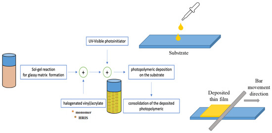
Figure 1.
Main technological steps used for the preparation of the sol-gel base photopolymer.
After the consolidation, films were exposed to a green light pattern for hologram recording and subsequently to halogen lamp to bleach the unreacted photoinitiator. The final refractive index modulation shown by this photopolymer is of about 0.02 [21]. This Δn saturation for green testing has been observed for a total dosage of about 35 mJ/cm2, revealing a good photosensitivity.
Moreover, ellipsometric spectroscopic analysis of the photopolymer obtained with sol-gel technique was performed at room temperature for three angles of incidence (θ = 60°, 65° and 70°), and in the spectral range of 300 to 1600 nm. A theoretical dielectric function based on the classical Lorentz dispersion model has been used to extract the optical parameters, i.e., the refractive index n and the extinction coefficient k from the measured ellipsometric spectra. The obtained spectral behaviours of the extinction coefficient and refractive index are both shown in Figure 2.
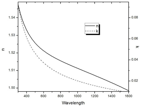
Figure 2.
Refractive index (solid line) and extinction coefficient (dashed line) of the sample extracted from ellipsometric measures.
With the aim to characterize the new photopolymer as a holographic recording material, a volume phase holographic grating was recorded, and its optical properties and performance were characterized.
2.2. Volume Holographic Grating
It is well known that a VHG diffracts the incident beam only when the Bragg phase-matching condition is satisfied. Without loss of generality, let us consider a non-slanted transmission grating, as reported in Figure 3. The Bragg condition is defined as:
where are the magnitude of the incident and diffracted wave vectors inside the medium, and is the grating vector magnitude, with grating period Λ.
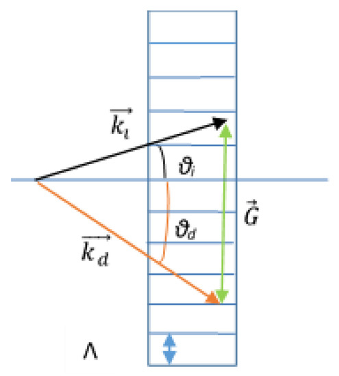
Figure 3.
Bragg condition for an unslanted VHG.
According to Kogelnik’s two-wave coupled wave theory [28], the efficiency with which thick holograms can diffract incident light depends on the deviation from the Bragg condition, highlighting angular and wavelength dependencies.
For VHGs, for a given grating spacing , the Bragg condition has only one solution of (θi, θd) for a given λ, or only one solution of λ for a given θi, in contrast to surface gratings, where the Bragg condition, at the same grating pitch G, can be satisfied with different diffraction orders m, different wavelengths λ = 2π/k, and different incidence angles θi, leading to the existence of multiple diffraction and scattering orders for a wide range of wavelengths.
2.3. Characterization of a Volume Holographic Grating
A grating of 494 lines/mm was obtained by using a typical Mach Zehnder interferometer. The recording light was a laser source at 532 nm (green source) with a maximum continuous power of 750 mW and a coherence length up to 100 m. Diffraction efficiency was measured during and after the holographic exposure by a He-Ne laser source at 632.8 nm with an output continuous power of 24 mW. Regarding the angular selectivity, it was investigated by measuring the diffracted intensity by the holographic grating as a function of the angle of incidence. We found that an exposure of less than 50 s is required to record an efficient grating [32,33].
In our previous paper, we demonstrated experimentally that this photosensitive material allows one to record volume holographic diffraction gratings with a very good diffraction efficiency of about 94% [33]; the acquired value was in good agreement with the efficiency obtained by model proposed by Koegelnik [28]. We also already demonstrated that the experimental grating angular selectivity curve obtained matches with the simulated theory values according to the Kogelnik’s coupled wave theory, and the corresponding full width at half maximum (FWHM) of these curves, which is the angular selectivity, was about 2° [33].
A confirmation that the recorded hologram is a volume and not a surface hologram can be obtained by evaluating a parameter called Q factor. Indeed, the criterion for determining whether a hologram is thick or thin is given by the Q factor as:
where λ is the recording wavelength, d is the photosensitive layer thickness, n is the refraction index of the material, and Ʌ is the fringe spacing. A holographic grating is classified as thin (surface hologram) when Q ≤ 1, thick (volume hologram) when Q ≥ 10 [34]. In our case, λ = 532 nm, d = 30 μm, n ≈ 1.5 and Ʌ = 2 μm, so we obtained a Q ≈ 17 confirming that our hologram is a volume holographic grating [32,33].
Finally, an atomic force microscopy (AFM) characterization was also performed on the recorded VHG to investigate the possible presence of a surface grating formed during the recording process [32,33]. AFM measurements showed a small sinusoidal surface modulation, possibly due to shrinkage, but its amplitude was less of 5 nm and then we can neglect it respect to volume grating.
2.4. Shrinkage
Due to shrinkage, the recording material thickness changes from d to d1 (d1/d = s). Thus, the orientation of the fringes in VHG will change from φ0 to φ1 as shown in Figure 4. Kogelnik’s coupled-wave theory for transmission phase volume gratings can be used to evaluate the change in the medium’s thickness during recording [35].
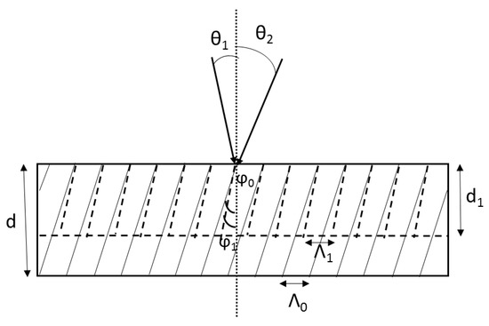
Figure 4.
Schematic diagram of the shrinkage process for transmitting holographic gratings.
Considering that in our case θ1 = 0° and θ2 = 15°, the internal angles are defined using Snell’s law as:
The grating has a tilt angle of φ0 and a spacing of Λ0 defined by:
where λ is the recording wavelength. The effect of shrinkage is modelled by the rotation of grating slant angle and reduction of grating period. The change in the grating tilt and spacing due to the writing process are:
The degree of volume shrinkage can be calculated by following equation [36]:
Since the change in grating slant angle is equal to the rotation of Bragg angle required for maximum diffraction efficiency, which changes with the change in Λ with shrinkage, the Bragg angular selectivity curve can be used to estimate the shrinkage in slanted transmission gratings by measuring the shift of the peak position. Thus, by fitting the angular Bragg selectivity curve with Kogelnik’s coupled-wave model [32], we obtained a final grating period of Ʌ1 = 2.02 μm, which leads to a degree of volume shrinkage of 0.978. As a result, a shrinkage value of 2.2% of the initial material thickness is obtained. Shrinkage compensation can be obtained by changing the thickness of the photopolymers [37] and/or by chemically modifying the sol-gel matrix [38].
It is important to note that although the commercial feasibility of a recording medium requires a 0.5% shrinkage as the upper limit [39,40,41], typically for various photopolymer formulations the shrinkage values reported in the literature are approximately 7–8% [42,43,44].
2.5. Temperature Charcterization of V-HOEs
For some applications, such as those in space environment, there are problems associated with a wide operating temperature range. For example, the temperature range in low-Earth orbit goes from −65 °C to +125 °C during each 90-min orbit. For this reason, to verify as a proof of concept the possibility to use our HOEs in these extreme environments, we performed a temperature characterization.
In order to carried out these characterizations, we recorded a VHG using the experimental set-up shown in Figure 5b with a diffraction angle α of 30° and without the cylindrical lens on the tilted path. According to Fourier Optics, the grating period can be evaluated using the following mathematical relationship [45]:
where λ is the recording wavelength (532 nm) and Ɵ is the angle between the two laser beams (=α). In our case, a VHG with 1000 lines per millimeter was obtained.
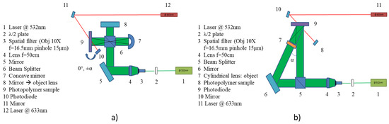
Figure 5.
(a) Experimental set-up for volume phase holographic spherical lenses recording; (b) Experimental set-up for volume phase holographic cylindrical lenses off-axis recording.
The VHG diffraction efficiency η can be theoretically evaluated as:
where λ is the wavelength of the incident laser beam, Δn is the modulation of the refractive index of the recording material, d is the photopolymer film thickness and θBragg is the Bragg diffraction angle [28,46].
In our experiments, we evaluated the diffraction efficiency using the relation:
where P1 is the measured power of the 1st diffraction order and P0 is the measured power of the zero-diffraction order. Here, absorption losses are neglected.
Using a He-Ne laser @ 633 nm (red light) and a power meter (mod. 1931-C, Newport), we measured the diffraction efficiency at room temperature (TR = 24 °C), at a given spatial point on the VHG. Then, we exposed the VHG to a temperature stress, to check the material tightness and test the performance in terms of diffraction efficiency. With this aim, we increased the temperature of the photopolymer, and so of the grating, to 150 °C for two hours. When the temperature was returned to TR, we again measured the diffraction efficiency at the same previous spatial point on the VHG. Finally, the temperature was lowered to −80 °C for 23 h and the diffraction efficiency was measured again on the same previous spatial point of the grating when the temperature was returned to TR. This thermal cycling analysis was repeated three times and the mean efficiencies measured at TR in the unperturbed condition and after two different thermal stresses with the corresponding standard deviation are summarized in Table 1.

Table 1.
Diffraction efficiency measured as a function of temperature.
As can be noticed, the diffraction efficiency evaluated on the same grating subjected to thermal stress does not change significantly. Indeed, after temperature variations, the diffraction efficiency remains fairly constant, even after three thermal cycles. Slight variations can be related to small errors in positioning of the red laser probe for measurement on the same spatial point.
Moreover, considering the absence of pressure under space conditions, a photopolymer outgassing test was carried out. After cleaning the grating with isopropanol, it was placed in a chamber connected with a turbo pump variation and a residual gas analyzer (RGA) consisting of a mass spectrometer. A test was performed at a base pressure of 2 × 10⁻⁸ mbar after 6 days of pumping at room temperature. The mass spectrometer reported the presence of only the main known gas species that are the contaminants based on the chamber. Then, a second test was conducted at a base pressure 7 × 10⁻⁸ mbar after 3 days of pumping at room temperature. The mass spectrometer highlighted the presence of unknown main gas species with atomic mass units up to 100. However, the intensity of this unknown gas is very low and comparable with the contaminants of the chamber of the test.
We are aware that the tests reported here require further extensive verification, just as we know that additional characterizations are mandatory before a material can be defined suitable for use in a space environment. Nevertheless, we can affirm that the results presented in this sub-section can be considered as a starting point for further study of this new photopolymer for its possible use in extreme environments.
3. Results and Discussions
With the aim of using a holographic grating as light deflectors and concentrators, gratings can be recorded by interference between a plane and a spherical or cylindrical wavefronts, obtaining a holographic lens. In our experiment, a 2 inches holographic spherical lens was registered with an in-line configuration by using a concave mirror with a focal length of 5 cm as object (Figure 5a), and an off-axis holographic cylindrical lens was recorded with an off-axis set-up using a commercial cylindrical lens with a focal length of 5.08 cm placed on the object beam (Figure 5b, α = 42°). In both configurations, the two interfering beams were of equal intensity at the surface of the recording medium, and a He-Ne laser source was used to monitor the 0th diffraction order in real time during the recording process.
The volume holographic lenses efficiencies η were calculated as the ratio of the power focused by the holographic lens (Pf_Holo_lens) to the power focused by a commercial Fresnel lens or a commercial in-line cylindrical lens (Pf_commercial_lens) with the same focusing features as the spherical and cylindrical volume holographic lenses, respectively [31]:
Holographic lenses, as well as commercial lenses, were illuminated by a beam with a diameter comparable to that of the lenses (≈4.5 cm and ≈1.5 cm for spherical and cylindrical lenses, respectively), and a power meter was positioned at the focal length. The evaluated efficiencies were of 42% and 25%, respectively. In order to have a point characterization, an efficiency measurement was performed on five regions along the transverse axis of the holographic spherical lens, as showed in Figure 6. The beam size was 1.7 mm ± 0.2 mm and each region was considered as a diffraction grating. The grating efficiency was evaluated as the ratio of the powers between the first-order and zero–order diffracted beams [28]; these powers were measured using a red laser. This characterization was repeated for several lenses, and the mean values obtained for each region are reported in Table 2. These results agree with theoretical predictions regarding the increase of the lines per mm from the central to the outer region [28]. Moreover, considering that the Fresnel lens has an efficiency nearly to 100%, the average value of the reported efficiencies is almost equal to that obtained in the previous case when the behaviour of the entire lens was characterized.
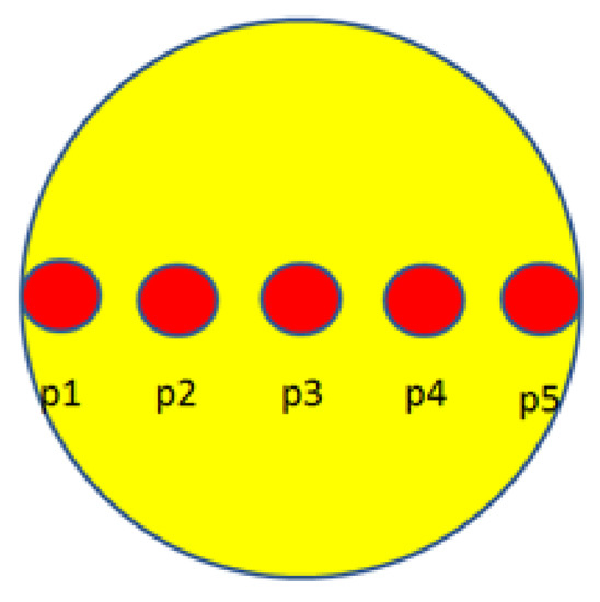
Figure 6.
Points along the lens axis considered for the measure of the efficiency.
Table 2.
Mean values and the relative standard error of the efficiency obtained for each region.
Although the efficiency for a Fresnel lens is greater than that of a holographic one, the latter has several advantages, such as: (i) flatness of the lens. Fresnel lenses present a curved part in the central region; (ii) less dependence on the polymer interface. Fresnel lenses present a series of concentric grooves on the polymer surface, so any change in the external environment can induce a variation in optical response. Whereas, Holographic lens are recorded into the volume of the material, so this dependence is less critical; (iii) less scattering dependence due to the absence of “steps”. As a Fresnel lens consists of discontinuities between individual facets, these “steps” tend to cause some scattering. This dependence is greater for off-axis light, so holographic lenses (iv) give the possibility to easily obtaining high-efficiency lenses for inclined illuminations. In additional, an important feature of volume holographic lenses is that they exhibit optimal efficiency at the wavelength for which they were designed. Light nearly to the designed wavelength is still diffracted according to the grating equation, but usually at a lower efficiency. At wavelengths sufficiently far from the Bragg condition, light passes through the holographic element without being diffracted [47]. Thus, considering that our lenses are designed for a wavelength of 532 nm and work well in the 400 to 700 nm range, while in the infrared region the lenses do not work, so thermal overheating of the photovoltaic cell is minimized, reducing cooling requirements.
Depending on the application, the holographic lens requires particular values of angular and/or wavelength selectivity. For these reasons, the hologram optical performances have been experimentally characterized, obtaining the holographic lens efficiency as a function of the incident angle and of the wavelength. It is important pointing out that the main difference between conventional optics and holographic optics is that to determine the direction of the image beam, Snell’s law is replaced by the grating equation [48,49].
Angular selectivity was investigated by measuring the diffracted intensity from the spherical holographic lens as a function of the angle of incidence. Two different laser sources, emitting at 532 nm and 633 nm, were used in order to consider different behavior of the lens at different wavelength. The experimental results of the angular scan at different incident wavelengths are showed in Figure 7 [31]. As expected, the angle at which the diffraction intensity is maximum is strictly related to the incident wavelength [50]. In particular, the angle increases with increasing wavelength. This behavior is due to Bragg phase-matching condition for VHG, as descripted in Section 2.2.
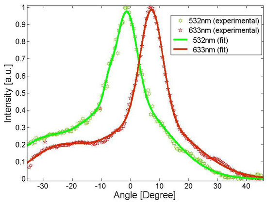
Figure 7.
Angular scan for the volume holographic lens at three different wavelengths. The interpolating fit lines in the figure are guide for the eye.
Additionally, the lens chromatic aberration has been investigated. Ideally, an optical lens should bring all the component colors of white light to a single point focus at the focal length of the lens. This means that the lens should refract all of the colors of white light equally, so they all intersect each other at the same location (or focus). Axial (or longitudinal) chromatic aberration is a measure of the difference in focus between the blue and red ends of the color spectrum caused by chromatic dispersion. The focal distance was measured at the wavelengths 442, 532, 633 and 975 nm for both a conventional and a holographic lens. The conventional lens was a 2 inches plano-convex lens with a focus distance of 6 cm, with a theoretical focal length given by the following simplified thick lens equation:
where n is the index of refraction and R is the radius of curvature of the lens surface. In our experiments, the conventional lens had R = 30.9 mm and was fabricated from N-BK7, so we used its refractive index of refraction at the wavelength of interest to approximate the wavelength-dependent focal length [51].
As reported in our previous work [31], while for the conventional lens the focal length slightly increases by increasing the incident wavelength, the holographic lens shows a marked decrease of the focal length by increasing the incident wavelength. This behavior can also be explained by considering the Bragg condition. In fact, Equation (1) can be rewritten as:
where θB is the Bragg angle. From Equation (12) it is clear that the Bragg angle increases as wavelength increases, leading to a shorter focal length. In particular, the focal length is related to θB, and hence to λ, by the geometrical relationship:
where D is the lens diameter.
The spherical holographic lens and the holographic cylindrical lens are HOEs and both follow the same mathematical laws. Therefore, we expect that also in the case of cylindrical holographic lenses, the behavior of the focal length as a function of the incident wavelengths is the same as that observed for the holographic in-line spherical lenses described in this section. Hence, we expect that the holographic cylindrical lens shows a decrease in the focal length by increasing the incident wavelength.
Finally, the beam profile in the focus of the holographic optical lenses were characterized and they were compared to the beam profiles acquired for both a conventional lens and for a Fresnel lens. Table 3 summarizes the evaluated beam widths as four times the standard deviation (4-sigma) for the four different lenses characterized. It is clear that the holographic spherical lens shows a reduced ability to concentrate light at the focal distance respect to the others two conventional lenses considered. Regarding the off-axis cylindrical lens, the beam width (4-sigma) along the y axis is significantly reduced in the lens focus, thereby drastically reducing the width along the y dimension. However, the beam diameter at the focal point of the two considered holographic lenses is quite comparable in size with the corresponding refractive optical lenses.
Table 3.
Beam width four sigma evaluated for four different lenses.
In order to compare the wavefront profile of the cylindrical holographic lens with the theoretical profile of an equivalent refractive lens, the intensity profile of the diffracted wavefront was acquired by scanning along the propagation axis (100 acquisitions with step of 5 μm), and at each scanning step the full width at half maximum (FWHM/2) was considered, as shown in Figure 8.
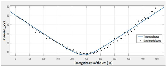
Figure 8.
Measured intensity profile of the wave front of the off-axis holographic cylindrical lens (black dots) and fit with a theoretical curve (solid blue line).
The experimental data (black dots in Figure 8) are compatible with the theoretical model, i.e., the pattern of a Gaussian laser beam through a lens (solid blue line in Figure 9), with a confidence interval of 98%, confirming the goodness of the optical quality of our HOEs. The properties of the holographic off-axis cylindrical lens to deflect and focus the light can be useful for the fabrication of holographic solar concentrators, allowing the size of photovoltaic cells to be reduced.
Figure 9.
(a) HOE recording for passive solar tracking. (b) Schematic behaviour of holographic system for passive solar tracking.
After recorded and characterized the simplest condition of a single volume holographic lens as solar concentrator, we moved to a lens array configuration. More complex structures based on overlapped holographic lenses were eventually considered to improve the concentration performance. In the following sub-sections, all the configuration considered (single holographic lens, holographic lenses array, and multiplexing of holographic lenses, recorded in different or in the same region) are reported and discussed.
All the different configurations proposed involve the use of holographic lens as light deflectors and concentrators. The single lens will act as concentrator, while the multiplexed holographic lenses will allow a passive tracking of the radiation source. Multiplexed holographic lenses could be achieved if, during the writing process, the same medium is used to record different holograms by varying the incident angle of the object wavefront each time. Thus, it is possible to realize a volume HOE that redirects the incident radiation on a single photovoltaic cell, regardless of the angle of illumination of the solar module, as schematically described in Figure 9. Considering that multiplexed holograms could show a lower diffraction efficiency due to overexposure of some regions [12], in these experiments we considered only holographic spherical lenses because the diffraction efficiency in this case is higher respect to a single holographic cylindrical lens, as reported before.
3.1. Recording of an Array of Four Volume Holographic Lenses
In order to realize a holographic lenses array, the recording system shown in Figure 10a has been realized. It allows recording four lenses on the same glass. Figure 10b shows the scheme of an array of four concentrator lenses, while in Figure 10c is reported a prototype solar panel obtained combining four glasses with four concentrator lenses recorded on each one.
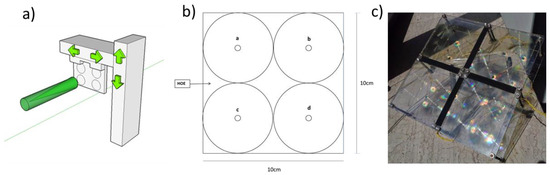
Figure 10.
(a) Writing system for the recording of array of four lenses on the same glass. (b) Array of four lenses recorded on the same glass; (c) a prototype of a solar panel obtained combining four glasses with four concentrator lenses recorded on each one.
3.2. Design and Realization of Multiplexed Holographic Lenses
Multiplexed and partial overlapped holographic lenses have been designed to direct the light in a fixed direction independently of the direction of incoming light. This configuration allows implementing a solar tracking without any mechanical movement (passive tracking). Thus, we assembled a stage that allows both the rotation and translation of the sample, in order to record an in-line lens for each direction of the sunlight.
In Figure 11, the writing procedure is schematically illustrated for three angles: perpendicular illumination (Figure 11a), +30° illumination (Figure 11b) and −30° illumination (Figure 11c). In Figure 11d, the passive tracking sunlight collection is conceptually illustrated.
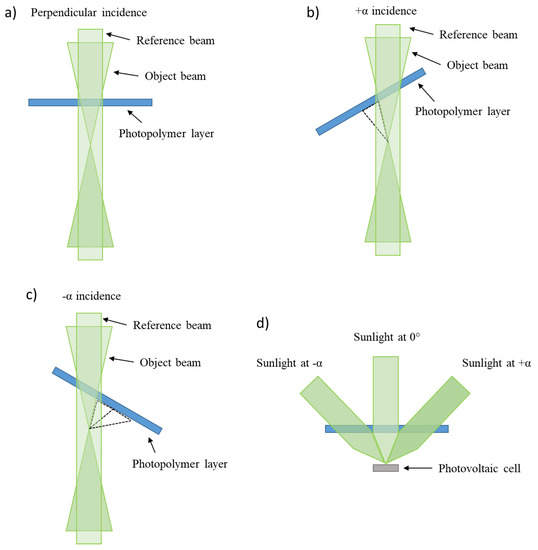
Figure 11.
Recording approach for three partially overlapped holographic lenses. Writing lens for a perpendicular (a), +α (b) and −α (c) incidence; (d) passive tracking collection of the sunlight.
An overlap among adjacent holographic lenses was adopted to optimize the sunlight collection. The overlapping area was determined by the geometry of the substrate and taking into account the diameter of each lens. In particular, the distance between the centres of two adjacent lenses was equal to the radius of the lens.
Adopting this system, two families of multiplexed or partially overlapped holographic lenses were written (Figure 12). Specifically, a set of three lenses (0°, ±30°) and five lenses (0°, ±15°, ±30°) were recorded on the same glass to focus the light on the same PV cell positioned close to the focus of the lens system.
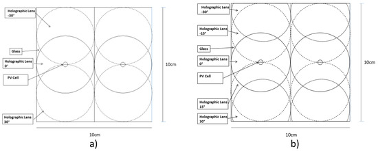
Figure 12.
Angular multiplex lenses at (a) three angles: 0° and ±30° and (b) five angles: 0°, ±15°, and ±30°.
The five multiplexed lenses were designed to achieve wide angular coverage, thus ensuring the passive solar tracking, while the three multiplexed lenses were considered in order to simplify the recording procedure.
3.3. Design and Realization of Multiplexed Holographic Lenses on the Same Area
Finally, a further study of multiplexing was made in a configuration different from the previous ones. This particular multiplexing consists of over-recording the same photopolymer region with different angles. In other words, the same surface area of photopolymer is used to record, in this preliminary test, two overlapped lenses, the first one is in in-line configuration, and the second one in off-axis configuration. This provides a more compact system than the multiplexed holographic lenses shown in the previous section.
In Figure 13, the writing procedure is schematically illustrated for four lenses: perpendicular illumination (Figure 13a), +42° illumination (Figure 13b), lateral shift and perpendicular (Figure 13c) and −42° (Figure 13d) incidence.
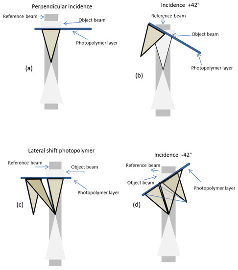
Figure 13.
Recording approach for a couple of holographic lenses recorded on the same area. Writing lens for a perpendicular (a), +42 (b), lateral shift and perpendicular (c) and −42 (c) incidence (d).
In this configuration, a couple of in-line and off-axis overlapped lenses was recorded, as shown in Figure 14. To record the off-axis lenses, the flat mirror of the recording set-up (optical element no. 8 in Figure 5a) was rotated.
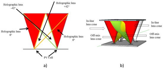
Figure 14.
Angular multiplex lenses obtained by overwriting the same photopolymer region with different angles: (a) bi-dimensional view, (b) three-dimensional view.
In Figure 14, both the bi-dimensional and three-dimensional operation principle of the proposed configuration is sketched.
3.4. Flexible V-HOE
Part of our study was dedicated to investigating the possibility of using alternative substrates to glass for the deposition of the holographic photopolymer. Since the glass induces a reduction of the transmittance, the use of glass substrates with a thickness of about 1 mm could be a limitation in the performance of V-HOEs. This limit could be even more pronounced with multiple layers. For this reason, it is important to reduce the thickness of the holographic film substrate material.
Thin polymeric sheets offer a good mechanical strength and the possibility of realizing flexible substrates. Polyethylene terephthalate (PET) with a thickness of 125 µm was used as substrate, and deposition tests were carried out using the bar coating technique, which showed a good wettability of the substrates by the holographic material. The consolidation phase also presented no particular problems. Figure 15 shows some details of the optical response of a VHG recorded on a flexible support.
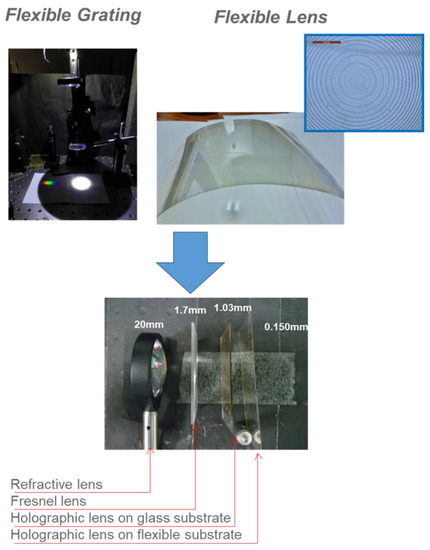
Figure 15.
V-HOEs recorded on a flexible support.
These results are very interesting especially in those applications where the lightest possible solution is desirable, such as in space applications. A significant volume reduction is also achieved as shown in Figure 15.
3.5. Optical Characterizations
All the realized concentrators, single lens, array of four lenses, multiplexing of three and five lenses, and overlapped crossed lenses, were optically characterized. To verify and test the light focusing ability of the holographic volume phase lenses, a silicon photodiode (FDS100, Thorlabs) with an active area of 12.96 mm2 (square with a size of 3.6 mm) was used as PV cell. Its wavelength range is 200–1100 nm, and the maximum of the spectral response is around 730 nm. Photodiodes were placed in the focus of the holographic lenses. To illuminate the structures, an LED (dragon1 PowerStar Whites-ILH-GD01, Osram) emitting white light was adopted. The LED was mounted on a goniometer, so the glass with the recorded lenses can be illuminated at different angles. The experimental setup was designed, and it is illustrated in Figure 16; this setup allows characterization at different incident angles, miming the position of the sun respect to the PV cells.
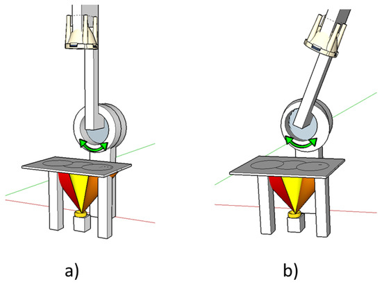
Figure 16.
Setup used to characterize the holographic lenses at different angles: (a) normal incidence, (b) angular incidence. Note: figure is not drawn to scale.
One of the most important parameters of the solar concentrators is the geometric concentration ratio C:
This is a strictly geometric definition, where A is the aperture area of the concentrator, i.e., of the lens, and Ar is the absorber surface area [52]. A high concentration ratio helps to reduce the cost of PV systems because a small area of the photovoltaic cell can collect over a large aperture. Considering that the diameter of each holographic lens was of 4.5 cm, the geometrical concentration obtained was of 123×.
All the light incident on the glass was focused on the PV cell located underneath it at a distance of 5 cm. The voltage characterization of the concentrator was obtained using a resistance of 50 Ω in parallel across the terminals of each PV cell.
The first characterization was performed on the single holographic lens with a normal incidence. In particular, the configuration illustrated in Figure 10b was analysed, i.e., four identical holographic lenses with four PV cells placed in the focus of each lens. Results are reported in Table 4, where the output voltage obtained by replacing the glass containing the lenses with one without lenses was also measured.
Table 4.
Output voltage obtained at PV cells positioned in the focus of each lens of the configuration illustrated in Figure 10b.
In Table 4, the degree of concentration of each lens is reported, too. This factor, expressed in number of “suns”, is defined as the ratio between the intensity of the light hitting the PV cell with and without concentration. The results show the good repeatability of the recording process. Additionally, each lens was characterized at different angles of incidence, and an angular selectivity of about ±8° was obtained.
In order to test the tracking efficiency of the multiplexed configurations, a characterization was carried out at different incidence angles of the light emitted by the Osram LED. The output voltages measured by each PV cell for each configuration at different angles of incidence is illustrated in Figure 17, whereas Table 5 summarizes the output voltages measured at the recording angle of each configuration. The values measured at different angles without lens are also reported in Table 5, in order to verify the concentrating behaviour of the realized V-HOEs.
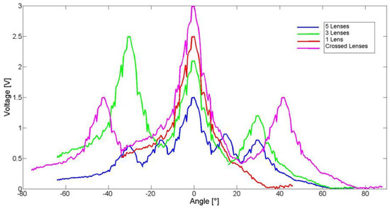
Figure 17.
Output of the PV cell at different angles of incident of the light for each configuration of the holographic lenses.
Table 5.
Voltage measured at the PV cell for each multiplexed configuration (three, five lenses and crossed lenses).
Furthermore, the five-lens configuration recorded considering the angular selectivity of each lens (±8°) and in order to obtain a wide angular coverage to ensure the passive solar tracking, was experimentally characterized under real operative conditions. The generated voltage of the photovoltaic system was continuously monitored during a clear day (24 h) and results are reported in Figure 18. The measurement was performed with the system tilted 30° backwards in order to be able to measure system performance at solar heights between −90° and 90°. During the monitored day, no mechanical movement of the five-lenses concentrator configuration was performed, so a passive solar tracking was achieved for a discrete range of time during periods of the day when the sun fulfils the recorded angle of each lens, as can clearly be seen in Figure 18. In order to obtain a complete solar tracking, the number of overlapped lenses or their angular selectivity should be increased.
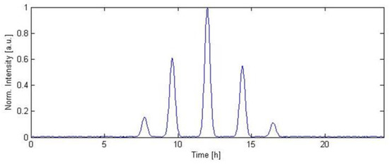
Figure 18.
24 h–Measurement of the concentrated solar intensity in real operative condition.
However, comparing all the realized solar concentrator configurations, the five-lens concentrator seems to be less convenient in terms of total harvested voltage than the three-lens configuration. Indeed, the degree of concentration is on average of 2.85 suns and 5.85 suns for the five- and three-lens configuration, respectively. The better performance of the three-lens system is due to less overlapped areas among the recorded lenses [9]. In fact, as can be seen in Table 5, the overlapping areas could reduce the focused power by about half compared to the first lens recorded at 0°. Finally, the concentrator with two overlapping cross-lenses shows a good behaviour at recording angles (normal incidence and ±42°), and the total harvested voltage is quite similar to the more complex five-lens configuration. Additionally, this system shows an average degree of concentration of 7.5 suns. Thus, further investigation of this configuration is required; in fact, the improvement and study of the two overlapping cross-lenses are still in progress.
4. Conclusions
In this paper, we have discussed about the possibility to use a sol-gel based photopolymer to record holographic lens. The sol-gel approach allows the formation of a silica-based matrix that provides a high mechanical ant thermic stability of the material. Moreover, the measured shrinkage value of 2.2% is less than the existing photopolymer materials that exibit a shrinkage value of 7–8%. Different holographic lenses were recorded and characterized either on rigid or flexible substrates with an in-line or off-axis configurations. Moreover, the holographic lenses were used to obtain single or multiplexed optical concentrators allowing to implement efficient solar concentrators with the possibility to perform passive solar tracking. For each structure, the recording holographic set-up has been described and the optical performances were measured in terms of diffraction efficiency, angular selectivity, multiangle acceptance, concentration factor. Finally, the generated voltage of a photovoltaic system coupled with a holographic multiplexed optical concentrator was continuously monitored without any mechanical movement of the holographic concentrator. The results confirm the possibility to use these holographic structures as potential passive solar tracker. As a final point, it is worth nothing that our holographic lenses were designed to be efficient in the visible range (spectral range 400–700 nm with a maximum efficiency at 532 nm), for the rest of the wavelengths the holographic elements are transparent. Therefore, in the solar spectrum region associated with wavelengths above 1200 nm and responsible for the overheating of PV cells, they do not work. This characteristic allows both ensuring optimal operating condition for the PV cells and a reduction in the complexity of the cooling systems.
5. Patents
Coppola, G.; Ferrara, M.A.; Borbone, F.; Roviello, A.; Striano, V.; Bianco, G. Materiale fotopolimerico per registrazione olografica. Italian Patent: Dep IT 26.10.2016, n. 102016000108108.
Author Contributions
Conceptualization, M.A.F. and G.C.; investigation, M.A.F., F.B. and G.C.; data curation, M.A.F., F.B. and G.C.; writing—original draft preparation, M.A.F. and G.C.; writing—review and editing, M.A.F. and G.C. All authors have read and agreed to the published version of the manuscript.
Funding
The APC was funded by PON: ARS01_01181-“PM3-Piattaforma Modulare Multi-Missione”, PON R&I 2014-2020, Ministry of University and Research.
Conflicts of Interest
The authors declare no conflict of interest. The funders had no role in the design of the study; in the collection, analyses, or interpretation of data; in the writing of the manuscript, or in the decision to publish the results.
References
- Leutz, R.; Suzuki, A. Space Concentrator Array. In Nonimaging Fresnel Lenses: Design and Performance of Solar Concentrators; Springer: Berlin, Germany, 2001; pp. 246–256. [Google Scholar]
- Nilsson, J. Optical Design and Characterization of Solar Concentrators for Photovoltaics; Printed by KFS AB, Lund; Faculty of Engineering, LTH at Lund University: Lund, Sweden, 2005; ISSN 1651-8136. ISBN 91-85147-15-X. [Google Scholar]
- Sangani, C.S.; Solanki, C.S. Experimental evaluation of V-trough (2 suns) PV concentrator system using commercial PV modules. Sol. Energy Mater. Sol. Cells 2007, 91, 453–459. [Google Scholar] [CrossRef]
- Ryu, K.; Rhee, J.G.; Park, K.M.; Kim, J. Concept and design of modular Fresnel lenses for concentration solar PV system. Sol. Energy 2006, 80, 1580–1587. [Google Scholar] [CrossRef]
- Davis, A. Fresnel lens solar concentrator derivations and simulations. Proc. SPIE 2011, 8129, 81290J. [Google Scholar] [CrossRef]
- Jing, L.; Liu, H.; Wang, Y.; Xu, W.; Zhang, H.; Lu, Z. Design and Optimization of Fresnel Lens for High Concentration Photovoltaic System. Intern. J. Photoenergy 2014, 2014, 539891. [Google Scholar] [CrossRef]
- Chekalin, A.V.; Andreeva, A.V.; Davidyuk, N.Y.; Sadchikov, N.A.; Malevskiy, D.A.; Pokrovskiy, P.V. Investigation of Solar Cell Overheating under Radiation of Ultrahigh Intensity. AIP Conf. Proc. 2018, 2012, 040001. [Google Scholar] [CrossRef]
- Nishijima, Y.; Komatsu, R.; Yamamura, T.; Balcytis, A.; Seniutinas, G.; Juodkazis, S. Design concept of a hybrid photo-voltaic/thermal conversion cell for mid-infrared light energy harvester. Opt. Mater. Express 2017, 7, 3484–3493. [Google Scholar] [CrossRef]
- Naydenova, I.; Akbari, H.; Dalton, C.; Yahya, M.; Tee Wei, C.P.; Toal, V.; Martin, S. Photopolymer Holographic Optical Elements for Application in Solar Energy Concentrators. In Holography—Basic Principles and Contemporary Applications; Mihaylova, E., Ed.; InTech: London, UK, 2013; pp. 129–145. [Google Scholar]
- Prim Solar Technologies. Available online: http://www.prismsolar.com (accessed on 10 October 2021).
- Castro, J.M.; Zhang, D.; Myer, B.; Kostuk, R.K. Energy collection efficiency of holographic planar solar concentrators. Appl Opt. 2010, 49, 858–870. [Google Scholar] [CrossRef]
- Chemisana, D.; Collados, M.V.; Quintanilla, M.; Atencia, J. Holographic lenses for building integrated concentrating photovoltaics. Appl. Energy 2013, 110, 227–235. [Google Scholar] [CrossRef]
- Marín-Sáez, J.; Atencia, J.; Chemisana, D.; Collados, M.D. Full modeling and experimental validation of cylindrical holographic lenses recorded in Bayfol HX photopolymer and partly operating in the transition regime for solar concentration. Opt. Express 2018, 26, A398–A412. [Google Scholar] [CrossRef] [PubMed] [Green Version]
- Shakher, C.; Ramamurthy, V. Thick transmission phase holograms for photovoltaic concentrator applications. Sol. Energy Mater. 1987, 16, 215–221. [Google Scholar] [CrossRef]
- Bainier, C.; Hernandez, C.; Courjon, D. Solar concentrating systems using holographic lenses. Sol. Wind Technol. 1988, 5, 395–404. [Google Scholar] [CrossRef]
- Ludman, J.E.; Riccobono, J.; Semenova, I.V.; Reinhand, N.O.; Tai, W.; Li, X.; Syphers, G.; Rallis, E.; Sliker, G.; Martín, J. The optimization of a holographic system for solar power generation. Sol. Energy 1997, 60, 1–9. [Google Scholar] [CrossRef]
- Zhang, Y.W.; Ih, C.S.; Yan, H.F.; Chang, M.J. Photovoltaic concentrator using a holographic optical element. Appl. Opt. 1988, 27, 3556–3560. [Google Scholar] [CrossRef] [PubMed]
- Al-Aaraji, H.H.; Tahir, K.J.; Ridha, N.J.; Mohammed, A.S.; Alosfur, F.K.M.; Mohammad, R.K.; Madlol, R. Preparation dichromate gelatin and its application as a holographic grating. AIP Conf. Proc. 2020, 2290, 050018. [Google Scholar]
- Akbari, H.; Naydenova, I.; Martin, S. Using Acrylamide Based Photopolymers for Fabrication of Holographic Optical Elements in Solar Energy Applications. Appl. Opt. 2014, 53, 343–1353. [Google Scholar] [CrossRef] [Green Version]
- Keshri, S.; Rogers, B.; Murphy, K.; Reynolds, K.; Naydenova, I.; Martin, S. Development and Testing of a Dual-Wavelength Sensitive Photopolymer Layer for Applications in Stacking of HOE Lenses. Appl. Sci. 2021, 11, 5564. [Google Scholar] [CrossRef]
- Ferrara, M.A.; Borbone, F.; Striano, V.; Coppola, G. Caracterization of photopolymers as optical recording materials by means of digital holography microscopy. In Optical Methods for Inspection, Characterization, and Imaging of Biomaterials; SPIE: Munich, Germany, 2013; Volume 8792, p. 87920Z. [Google Scholar]
- Coppola, G.; Ferrara, M.A.; Borbone, F.; Roviello, A.; Striano, V.; Bianco, G. Materiale Fotopolimerico Per Registrazione Olografica. Patent No. 102016000108108, 26 October 2016. [Google Scholar]
- Hsieh, M.L.; Lin, S.H.; Hsu, K.Y.; Burr, J.A.; Lin, S.Y. An Efficient Solar Concentrator Using Volume Hologram; Paper PDPB8; OSA/CLEO: Baltimore, MD, USA, 2011; ISBN 978-1-55752-910-7. [Google Scholar]
- Ranjan, R.; Khan, A.; Chaktaborty, N.R.; Yadav, H.L. Use of holographic lenses recorded in dichromated gelatin film for PV concentrator applications to minimize solar tracking. In Proceedings of the 3rd WSEAS International Conference on Energy Planning, Energy Saving, Environmental Education, Tenerife, Spain, 1–3 July 2009; pp. 49–52, ISSN 1790-5095. ISBN 978-960-474-093-2. [Google Scholar]
- Akbari, H.; Naydenova, I.; Persechini, L.; Garner, S.M.; Cimo, P.; Martin, S. Diffractive Optical Elements with a Large Angle of Operation Recorded in Acrylamide Based Photopolymer on Flexible Substrates. Int. J. Polym. Sci. 2014, 2014, 918285. [Google Scholar] [CrossRef]
- Torrey, E.R.; Ruden, P.P.; Cohen, P.I. Performance of a split-spectrum photovoltaic device operating under time-varying spectral conditions. J. Appl. Phys. 2011, 109, 074909. [Google Scholar] [CrossRef]
- Volkovich, V.A.; Griffiths, T.R. Catalytic Oxidation of Ammonia: A Sparkling Experiment. J. Chem. Educ. 2000, 77, 177. [Google Scholar] [CrossRef]
- Kogelnik, H. Coupled-wave theory of thick hologram gratings. Bell Syst. Tech. J. 1969, 48, 2909–2947. [Google Scholar] [CrossRef]
- Renk, K.; Jacques, Y.; Felts, C.; Chovit, A. Holographic Solar Energy Concentrators for Solar Thermal Rocket Engines (No. NTS-6006). Nts Engineering Long Beach Ca. 1988. Available online: https://apps.dtic.mil/sti/pdfs/ADA198807.pdf (accessed on 10 October 2021).
- Loicq, J.; Venancio, L.M.; Stockman, Y.; Georges, M.P. Performances of volume phase holographic grating for space applications: Study of the radiation effect. Appl. Opt. 2013, 52, 8338–8346. [Google Scholar] [CrossRef] [PubMed] [Green Version]
- Ferrara, M.A.; Bianco, G.; Borbone, F.; Centore, R.; Striano, V.; Coppola, G. Volume Holographic Optical Elements as Solar Concentrators. In Holographic Materials and Optical Systems; Naydenova, I., Nazarova, D., Babeva, T., Eds.; InTech: London, UK, 2017; pp. 27–50. ISBN 978-953-51-3038-3. [Google Scholar]
- Bianco, G.; Ferrara, M.A.; Borbone, F.; Roviello, A.; Striano, V.; Coppola, G. Photopolymer-based volume holographic optical elements: Design and possible applications. J. Eur. Opt. Soc.-Rapid 2015, 10, 15057. [Google Scholar] [CrossRef] [Green Version]
- Bianco, G.; Ferrara, M.A.; Borbone, F.; Roviello, A.; Pagliarulo, V.; Grilli, S.; Ferraro, P.; Striano, V.; Coppola, G. Volume holographic gratings: Fabrication and characterization. Proc. SPIE 2015, 9508, 950807. [Google Scholar] [CrossRef] [Green Version]
- Kress, B.C.; Meyureis, P. Applied Digital Optics: From Micro-Optics to Nanophotonics; John Wiley & Sons: Hoboken, NJ, USA, 2009; p. 638. ISBN 978-0-470-02263-4. [Google Scholar]
- Gallo, J.T.; Verber, C.M. Model for the effects of material shrinkage on volume holograms. Appl. Opt. 1994, 33, 6797–6804. [Google Scholar] [CrossRef]
- Cho, Y.; Kawakami, Y. High Performance Holographic Polymer Dispersed Liquid Crystal Systems Formed with the Siloxane-containing Derivatives and Their Applications on Electro-optics. In Advances in Lasers and Electro Optics; Costa, N., Cartaxo, A., Eds.; InTech: London, UK, 2010; p. 838. ISBN 978-953-307-088-9. [Google Scholar]
- Moothanchery, M.; Bavigadda, V.; Toal, V.; Naydenova, I. Shrinkage during holographic recording in photopolymer films determined by holographic interferometry. Appl. Opt. 2013, 52, 8519–8527. [Google Scholar] [CrossRef] [PubMed]
- Ramos, G.; Alvarez-Herrero, A.; Belenguer, T.; del Monte, F.; Levy, D. Shrinkage control in a photopolymerizable hybrid solgel material for holographic recording. Appl. Opt. 2004, 43, 4018–4024. [Google Scholar] [CrossRef] [PubMed]
- Coufal, H.J.; Psaltis, D.; Sincerbox, G.T. (Eds.) Holographic Data Storage; Springer Series in Optical Sciences; Springer: Berlin/Heidelberg, Germany, 2000. [Google Scholar]
- Dhar, L.; Schones, M.G.; Wysocki, T.L.; Bair, H.; Schilling, M.; Boyd, C. Temperature-induced changes in photopolymer volume holograms. Appl. Phys. Lett. 1998, 73, 1337–1339. [Google Scholar] [CrossRef]
- Gallego, S.; Márquez, A.; Méndez, D.; Ortuño, M.; Neipp, C.; Fernández, E.; Pascual, I.; Beléndez, A. Analysis of PVA/AA based photopolymers at the zero spatial frequency limit using interferometric methods. Appl. Opt. 2008, 47, 2557–2563. [Google Scholar] [CrossRef] [PubMed] [Green Version]
- Dietz, J.E.; Peppas, N.A. Reaction kinetics and chemical changes during polymerization of multifunctional (meth)acrylates for the production of highly crosslinked polymers used in information storage systems. Polymer 1997, 38, 3767–3781. [Google Scholar] [CrossRef]
- Endo, T.; Sanda, F. Ring-opening polymerization, anionic (with expansion in volume). In Polymeric Materials Encyclopedia; CRC Press: Boca Raton, FL, USA, 1996; Volume 10, pp. 7550–7554. [Google Scholar]
- Schmidt, C.; Scherzer, T. Monitoring of the Shrinkage during the Photopolymerization of Acrylates Using Hyphenated Photorheometry/Near-Infrared Spectroscopy. J. Polym. Sci. Part B Polym. Phys. 2015, 53, 729–739. [Google Scholar] [CrossRef]
- Saleh, B.E.A.; Teich, M.C. Fundamentals of Photonics, 2nd ed.; Wiley: Hoboken, NJ, USA, 2007. [Google Scholar]
- Goodman, J.W. Introduction to Fourier Optics, 2nd ed.; McGraw-Hill: New York, NY, USA, 1996. [Google Scholar]
- Baldry, I.K.; Bland-Hawthorn, J.; Robertson, J.G. Volume phase holographic gratings: Polarization properties and diffraction efficiency. Publ. Astron. Soc. Pac. 2004, 116, 403–414. [Google Scholar] [CrossRef]
- Close, D.H. Holographic Optical Elements. Opt. Eng. 1975, 14, 408–419. [Google Scholar] [CrossRef]
- Ferrara, M.A.; Striano, V.; Coppola, G. Volume Holographic Optical Elements as Solar Concentrators: An Overview. Appl. Sci. 2019, 9, 193. [Google Scholar] [CrossRef] [Green Version]
- Barden, S.C.; Arns, J.A.; Colburn, W.S. Volume-phase holographic gratings and their potential for astronomical applications. In Optical Astronomical Instrumentation; SPIE: Kona, HI, USA, 1998; Volume 3355, p. 866. [Google Scholar] [CrossRef] [Green Version]
- Thorlabs. Available online: http://www.thorlabs.de/newgrouppage9.cfm?objectgroup_id=3279 (accessed on 10 October 2021).
- Rabl, A. Active Solar Concentrators and Their Applications; Oxford University Press: Oxford, UK, 1985; ISBN 0-19-503546-1. [Google Scholar]
Publisher’s Note: MDPI stays neutral with regard to jurisdictional claims in published maps and institutional affiliations. |
© 2021 by the authors. Licensee MDPI, Basel, Switzerland. This article is an open access article distributed under the terms and conditions of the Creative Commons Attribution (CC BY) license (https://creativecommons.org/licenses/by/4.0/).