1. Introduction
Periodic structures are the subject of constant research, stimulated by the emergence of new materials and problems that require new properties of structures and elements based on them. In previous years, the greatest interest was shown in volume holographic gratings and was associated with the possibility of obtaining highly selective properties and using them as selective elements. In recent years, problems have appeared that require holographic optical elements combining high diffraction properties with a wide range of angles of radiation incidence. These elements include elements of holographic solar concentrators.
In the available publications, along with focusing elements [
1,
2,
3,
4], diffractive deflectors are considered, which redirect radiation in a wide range of angles in one direction [
5,
6,
7,
8,
9,
10,
11]. The main requirement for such elements is the combination of high diffraction efficiency with a wide range of angles of incidence. However, their diffraction properties are traditionally investigated in a relatively narrow angular range and mainly when the radiation is incident in one plane. So, in a number of works, the selective properties are determined according to the traditional scheme, which leads to narrow contours of angular selectivity [
2,
6,
9,
11] that thereby lead to the concept of creating stacked volume gratings [
6,
8,
11] or the use of nonvolume gratings [
7] to expand the angular range. There is also the concept of using specific materials with an increase in refractive index modulation [
7,
8,
10].
In this work, we present the results of a detailed experimental study of the diffractive and selective properties of nonslanted and slanted periodic structures in promising photopolymer materials in a wide range of incident angles in three-dimensional space, which revealed new data on the selectivity of these structures that can be used to quantify their angular range in a set of planes for practical applications, including the creation of diffractive deflectors for solar energy.
2. Materials and Methods
Transmission holographic gratings were recorded by radiation from a helium–neon laser with a wavelength of 633 nm, and a helium–cadmium laser with a wavelength of 442 nm.
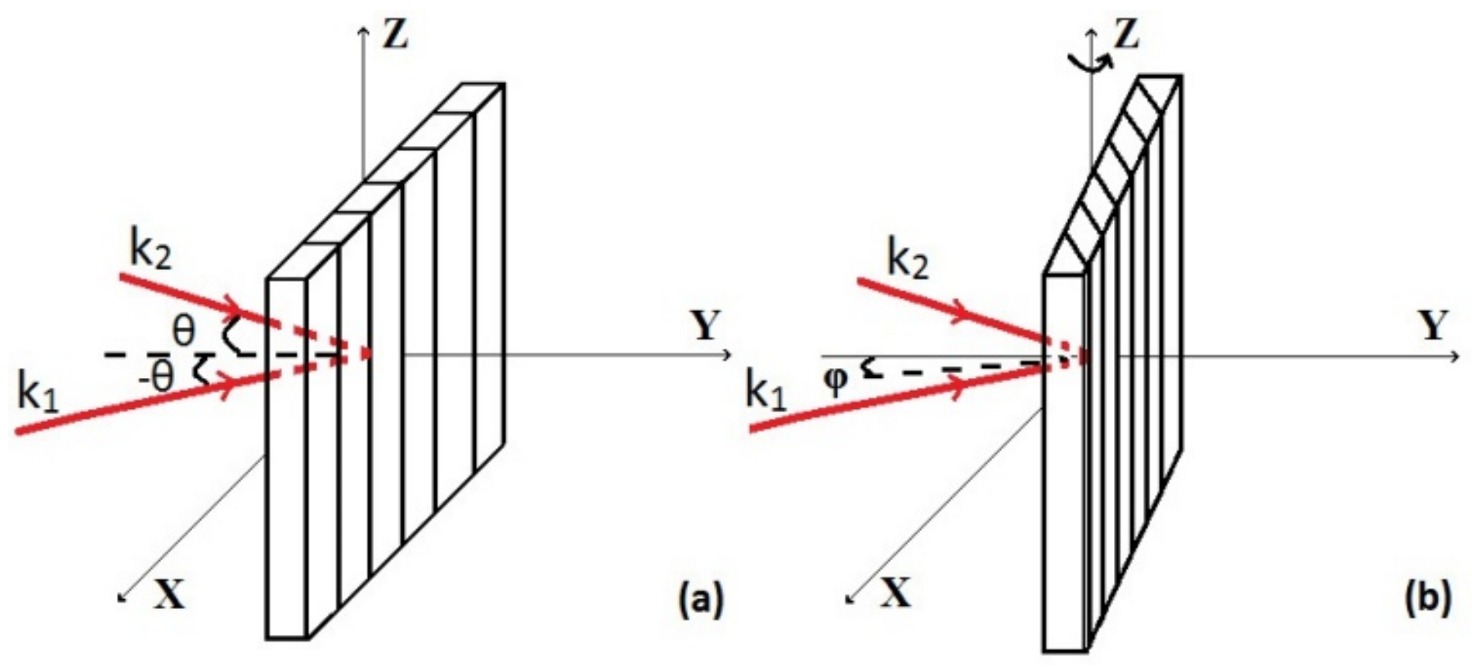
Figure 1 shows the recording schemes for nonslanted and slanted gratings. Vectors of incident waves k
1 and k
2 of the interfering waves during recording lay in the XY plane; thus, the formed dielectric planes were perpendicular to the plane of incidence. When writing nonslanted gratings, the normal to the surface coincides with the Y axis. When writing slanted gratings, the sample is rotated around the Z axis by an angle ϕ.
Industrial photopolymer materials Bayfol HX (Covestro AG) on a film base [
12] and a photopolymerizable monomeric acrylate composition based on commercial components [
13] were used as recording media.
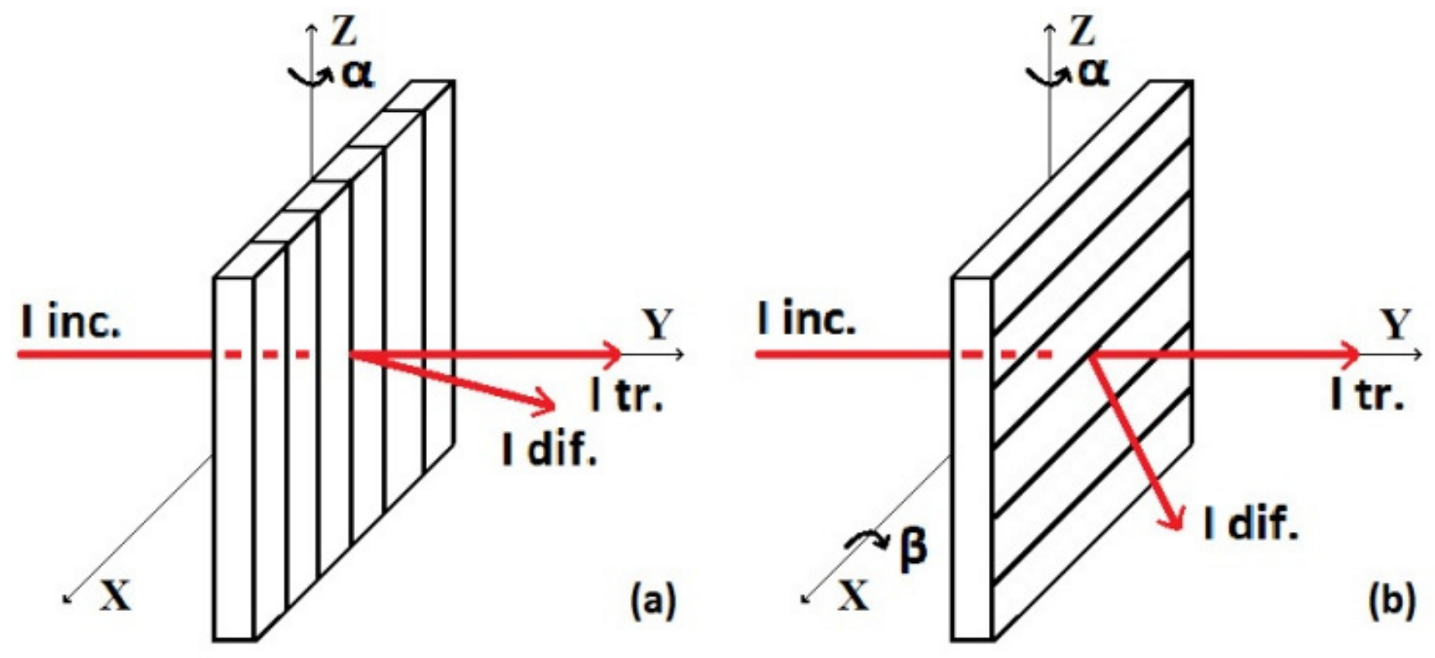
To study the diffraction characteristics of the structures, an experimental setup was used that allowed for measuring diffraction efficiency when the sample is rotated (with an accuracy of about ±1°) in two mutually perpendicular directions according to
Figure 2a,b.
Scheme 1 in
Figure 2a is conventionally used to measure the diffraction efficiency of gratings and determine their angular selectivity [
2,
6,
11]. The grating is installed on the rotation stage, so that the dielectric planes (fringes) are perpendicular to the plane of the stage, that is, the XY plane. When measuring diffraction efficiency according to this scheme, only the angle of rotation of the grating around the Z axis changes, that is, angle α. Most measurements were carried out according to Scheme 2 in
Figure 2b. The grating in the initial position was set so that the dielectric planes were parallel to the XY plane (when the sample was rotated by 90°). When measuring according to Scheme 2, the angle of rotation of the grating around the X axis changes—angles β and α.
Diffraction efficiency (DE) was determined at a wavelength of 650 nm as the ratio of radiation intensity in the first diffraction order to the incident radiation intensity. The choice of wavelength was determined by the traditional use of radiation in the red range of the spectrum for measuring the diffraction efficiency of holographic elements of solar concentrators [
2,
6,
7], and the spectrum of solar radiation and spectral sensitivity of the most common solar cells, as given in [
9].
3. Results
3.1. Diffractive Properties of Nonslanted Structures
Let us consider the properties of nonslanted volume gratings recorded in the Bayfol HX photopolymer. Results shown in
Figure 3 and
Figure 4 refer to the structures recorded in the area of optimal conditions from the point of view of obtaining the maximal diffraction efficiency, found experimentally and presented in our previous article [
14]. Structures were recorded under the following conditions: the wavelength of the recording radiation was 633 nm, the angle between the beams was 23°, the period of the structures was 1.6 μm, and exposure time was 10 s (at power density of 12 mW/cm
2). In accordance with the Klein criterion [
15] Q = 17, that is, the gratings were volume.
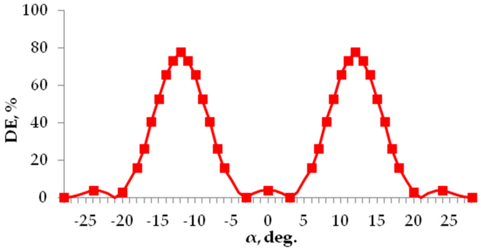
Diffraction efficiency measured using Scheme 1 demonstratef the conventional contour of angular selectivity (similar to that reported in previous studies [
2,
6,
11]), as shown in
Figure 3. Maximal efficiency (80%) was only achieved when the radiation was incident at the Bragg angle (ϴ
Br = ±12°). In this case, the contour of angular selectivity was narrow (about 8° at half width).
Measurements according to Scheme 2 (when the sample was rotated by 90°) produced more interesting results (partially considered in our other article [
14]). Other authors [
9] showed the possibility to obtain a wide contour of angular selectivity (with a half width of about 80° and maximal diffraction efficiency in the angular range of about 40°) by varying the incident direction along the plane perpendicular to the two recording beams.
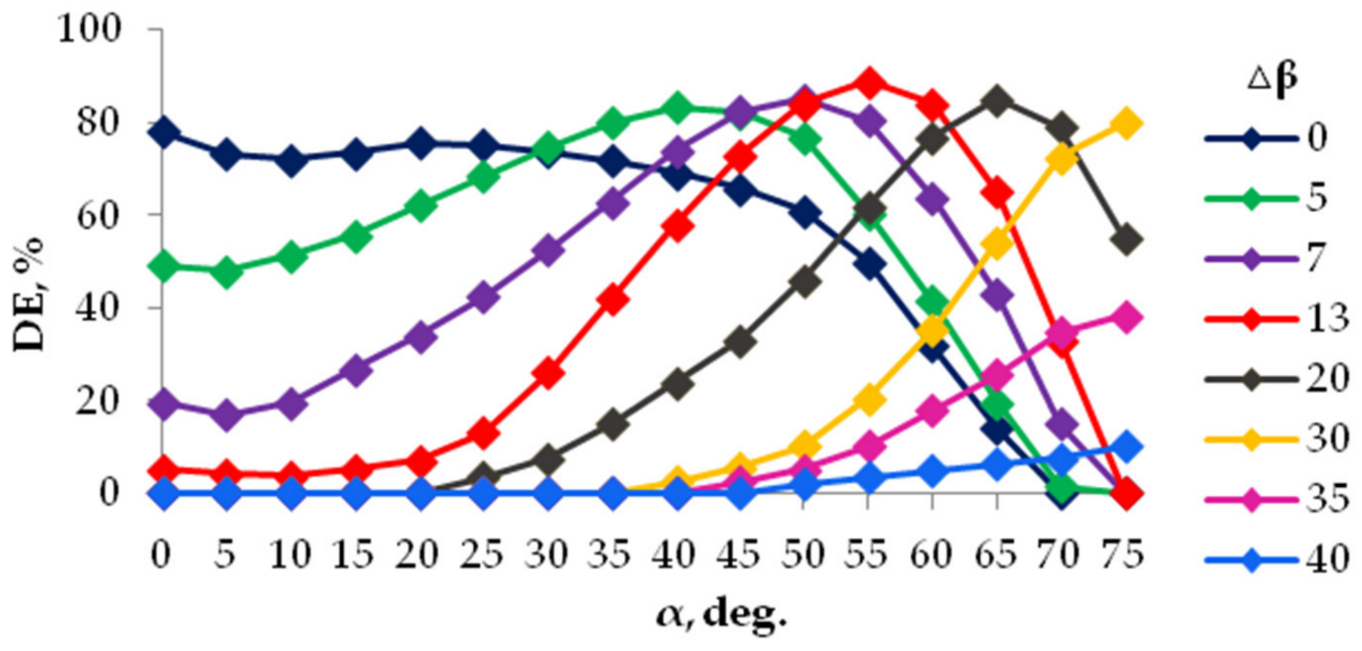
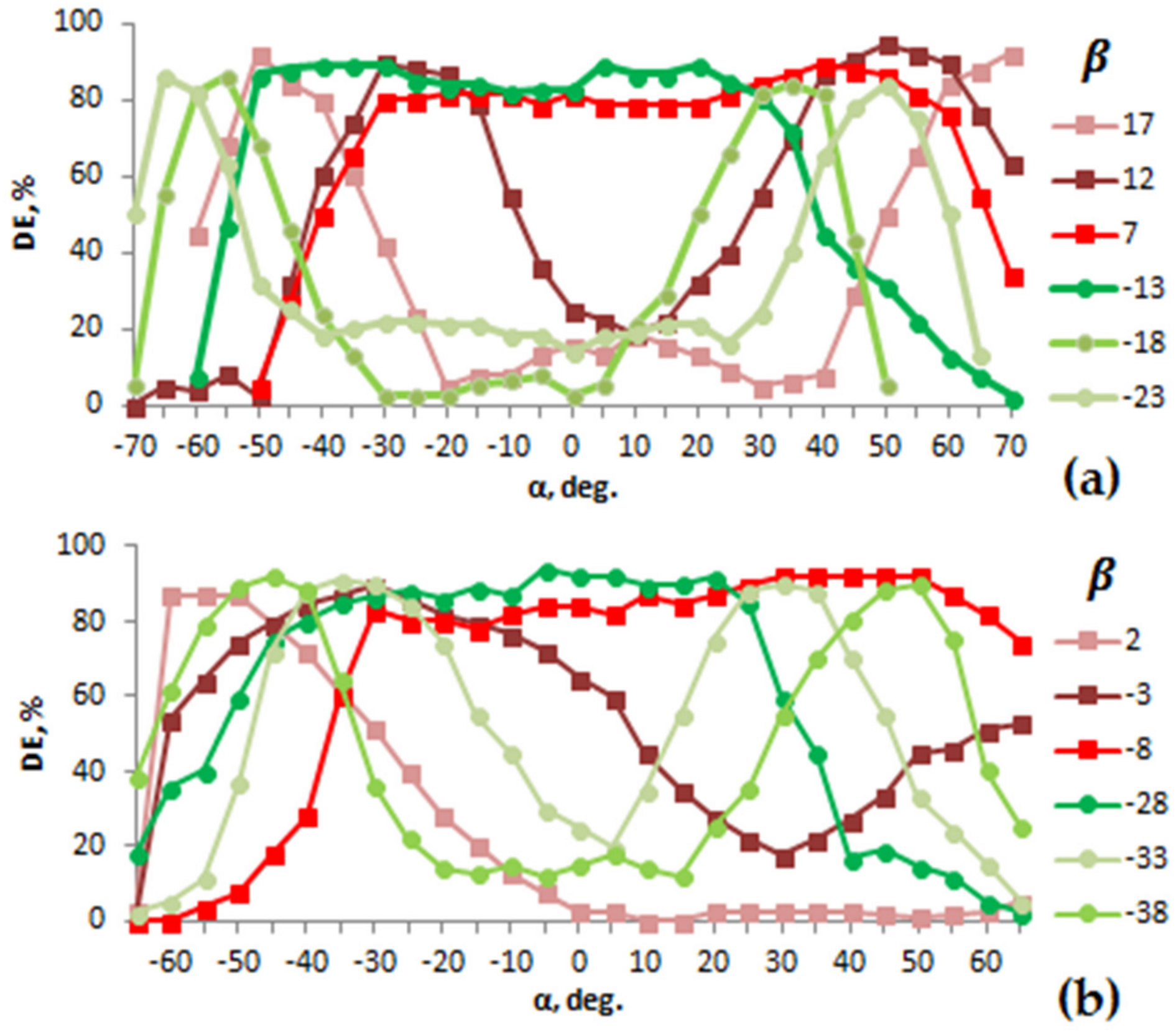
Figure 4 shows the diffraction-efficiency dependence on angles α and β. Curves were obtained on the basis of statistical processing of the results of several experiments on recording gratings and measurements carried out by independent researchers. Good reproducibility of results was obtained. Curves in
Figure 4 are shown for positive values of the angle α (for better representation of data details), since, for negative values α, curves for a nonslanted grating were symmetrically positioned about the vertical axis.
The following trends were observed in the received data. If β = ϴ
Br = ±12°, that is, the directions of the incident radiation lay in a plane rotated around the X axis by the Bragg angle, which we call the Bragg plane, the maximal values of the diffraction efficiency remained in a wide range of angles α—more than 80°, that is, the angular selectivity contour was wide, with a half width of about 120°. In
Figure 4, this contour corresponds to the blue curve.
With an increase in angle β relative to the Bragg angle by values of Δβ from 5° to 40°, that is, with a deviation from the Bragg plane, a shift in the position of the diffraction efficiency maxima towards greater angles α was observed up to 70°. In this case, the angular selectivity contour remained rather wide.
The given dependences indicate that there existed directions of radiation incidence on the grating that differed from the classical Bragg direction, corresponding to oblique transmission, at which the maximal values of diffraction efficiency were achieved.
Similar trends of change in the diffraction efficiency with varying angles α and β were obtained for volume gratings recorded on acrylate composition.
The established properties of the structures can be explained using Kogelnik’s theory [
16]. The constancy of diffraction efficiency when radiation was incident in the Bragg plane can be easily explained by the retention of the Bragg angle (β = ϴ
Br) with a change in α, that is, the lack of a change in the periodicity in the α direction. When deviating from the Bragg plane, the possibility of using this theory is determined by the fact that the obtained maximal diffraction efficiency for oblique transmission of radiation through the structure is equal to the diffraction efficiency measured according to Scheme 1. Experimental findings can be explained by numerically solving the coupled wave equations using the dephasing parameters determined by angles α and β given in
Figure 4. In this work, we experimentally investigate the possibility of obtaining high diffraction efficiency in a wide range of angles of incidence and at great angles of incidence of more than 70°, and demonstrate that it can be useful for solving practical problems, including solar energy.
Let us now turn to the properties of hybrid structures. A hybrid structure is a volume grating with refractive index modulation, on the surface of which a relief grating is formed. In our works [
14,
17], the possibility of obtaining hybrid structures in acrylate compositions was shown. Gratings with a significant relief height were formed in a narrow range of exposures. The maximal diffraction efficiency of the relief component of the hybrid structure was more than 40%, that is, the gratings were quasivolume.
Figure 5 shows the diffraction characteristics of hybrid structures, obtained by measuring the diffraction efficiency according to Scheme 2, for structures recorded under optimal conditions that ensure the maximal diffraction efficiency of the volume and relief components of the structure (recording radiation wavelength was 442 nm, exposure time was 40 s at a power density of 3 × 10
−2 W/cm
2, and the period of the structures was 3 μm).
The Bragg planes corresponded to angle β = ϴBr = ±6°. When the directions of the incident radiation lay in these planes, the maximal diffraction efficiency remained in the range of angles α about 100°. With a slight increase in angle β by Δβ = 2–5°, the properties of the volume component of the hybrid structure were observed. The observed trends in the change in diffraction efficiency were similar to the trends obtained for a volume grating. The position of the maxima shifted towards greater values of α. With a further increase in β, that is, for Δβ up to 60°, the contribution of the relief component of the hybrid structure is appeared. Sufficiently high values of diffraction efficiency—more than 45% are provided in the range of angles α more than 140° and angles β more than 60°.
Thus, hybrid structures have an advantage over volume gratings of a significant increase in the range of angles β, in which sufficiently high values of the diffraction efficiency are provided.
3.2. Diffractive Properties of Slanted Structures
Gratings with different slant angles of dielectric planes in the range of 5–30° with an interval of 5° were recorded in the material Bayfol HX. Recording conditions were similar to those for nonslanted gratings.
Measurements of the diffraction efficiency of slanted gratings according to the conventionally used Scheme 1 give classical angular selectivity contours close to those for nonslanted gratings with a slight increase in the maximal values of the diffraction efficiency and half width of the contour with an increase in the slant angle.
Using gratings with slant angles of 5° and 20° as an example, consider the results for Scheme 2 shown in
Figure 6.
For a grating with a slant angle of 5°, there were two Bragg planes that, in contrast to nonslanted gratings, were asymmetrically located relative to the normal to the grating surface and corresponded to angles β of about +7° and −13°. For the directions of radiation incidence in these planes, the maximal diffraction efficiency remains in the range of angles α about 80°. With increasing angles β, the maxima, as for nonslanted gratings, shifted towards greater angles α.
For a grating with a dielectric planes slant of 20°, similar trends were observed. However, the Bragg planes were located on one side of the normal to the grating surface and corresponded to angles β of −8° and −28°.
4. Discussion of Structural Properties in Relation to Solar-Energy Problems
The 3D graphs for the wide range of incident angles presented in
Figure 7 show a comparison of the properties of the considered structures. The directions of radiation incidence—the values of the angles α and β, and ranges of the incident angles at which the diffraction efficiency was maximal were clearly visible. Curves corresponding to Bragg planes are highlighted in black.
The total range of incident angles at high diffraction efficiency was wider than the ranges presented in the literature [
5,
6,
7,
8,
9,
10,
11], where the working range was obtained at angles α of about 40°, and investigations with changing angles β were not carried out.
The obtained dependences of diffraction efficiency on the angle of incidence allowed for choosing the type of structures or their combination for use as diffractive deflectors, and optimizing the gratings’ orientation for the range of incident angles determined by the trajectory of the Sun’s motion for a limited or long time range. Of greatest interest is the use of gratings without reorientation for a long time.
Below, we present the results of evaluating the efficiency of the considered structures, taking into account the trajectories of the Sun for two different latitudes—Sochi and St. Petersburg, corresponding to Figures 2.10 and 2.11.C in the book [
18] for a period of spring–autumn.
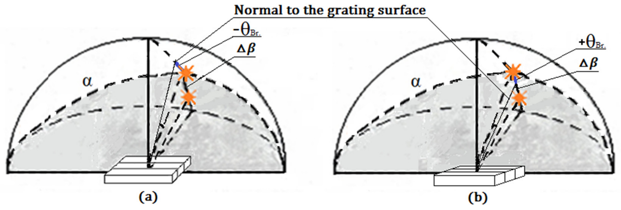
Nonslanted gratings (volume and hybrid) in the initial stationary position were assumed to be oriented, so that the angles between the normal to the grating surface and the direction to the Sun at its maximal height above the horizon corresponded to the Bragg angles. In this case, two orientations are considered: using one Bragg angle (−ϴ
Br), position 1 as shown in
Figure 8a, and two Bragg angles (−ϴ
Br and +ϴ
Br), position 2 as shown in
Figure 8b.
To evaluate the efficiency of gratings for angles of incidence corresponding to azimuthal angles and height above the horizon for a given time of day and season, in accordance with
Figure 8, the dependences of the diffraction efficiency on angles α and ∆β, shown in
Figure 3 and
Figure 4, were used. Angles α correspond to azimuthal angles. The values of Δβ for nonslanted gratings at Position 1 corresponding to ϴ
Br = −12° for a volume grating and ϴ
Br = −6° for a hybrid structure were found to be
where δ
max is the maximal height of the Sun above the horizon, δ
t is the height of the Sun above the horizon for a specific time, Δδ is the change in altitude above the horizon relative to the maximal altitude (for summer, noon).
With initial Position 2 corresponding to ϴ
Br = +12° for a volume grating and ϴ
Br = +6° for a hybrid structure, the values of Δβ were determined to be
For slanted gratings with a slant angle of 20° providing the best characteristics the results are given for two initial positions: in position 1, the direction to the Sun at its maximal height above the horizon coincides with the normal to the grating surface, in position 2, the direction to the Sun corresponds to the Bragg angle ϴ
Br = −8°. To assess the efficiency of the gratings, we used the dependences of the diffraction efficiency on angles α and β, shown in
Figure 6b. Angles β for Position 1 were found to be
and, for Position 2,
Results are shown in
Table 1 and
Table 2. In the columns of the tables, 1 and 2 indicate the position of the grating.
One can see the advantage of grating orientation to use two Bragg angles (Position 2) for nonslanted volume gratings and hybrid structures, especially for the period of spring and autumn for morning and evening (8–9 am and 3–4 pm) for both latitudes—St. Petersburg and Sochi. The advantage of position 2 for hybrid structures in the summer is related to the possibility of better use of the properties of the volume component of the structure. The contribution of the relief component, in spite of the lower values of the diffraction efficiency, determined the lower criticality to the angles of incidence over the entire considered time range.
In terms of efficiency during the entire spring–autumn period, the best results were obtained for volume gratings. There was a possibility of obtaining high efficiency in the morning and evening (8–9 am, 3–4 pm), corresponding to great azimuthal angles (60–75°) for the latitude of St. Petersburg. The absence of some data for the morning and evening time, in particular for the latitude of Sochi, was due to the absence of experimental results for angles α greater than 75°, at which the radiation enters the end of the sample at its large inclinations. However, an increase in efficiency for great angles can be achieved by adjusting the grating position for angle α. So for example, for Sochi at 8 am with an angular shift equal to 10°, efficiency of 0.8 can be obtained.
For slanted gratings, there is a greater criticality to the incident angles and the grating orientation compared to nonslanted gratings. However, with optimal grating orientations, the greatest gain can be obtained for a limited time period. So, for example, when the grating is installed in Position 1 in relation to the Sun trajectory for St. Petersburg, the highest efficiency of up to 0.9 during the day (9 am–3 pm) was achieved for the period of spring and autumn. For the trajectory of Sochi for the same period, spring and autumn, a fairly good result during the day (10 am–2 pm) gave Position 2.
By using the discussed elements as diffractive deflectors, it is possible to obtain gains in the use of solar energy compared to using only a solar cell without tracking. So, for azimuthal angles up to 75° (8–9 am), taking into account the cosine dependence of the photocell signal on the angle of radiation incidence, up to threefold gain can be obtained.
Obtained results on the correction of the diffraction efficiency of the structures at angles of incidence determined by the trajectory of the Sun are largely determined by the established dependences of the diffraction efficiency on the angles α and β, namely, by the established shift of the position of the maximum towards great angles α with increasing angles β.
We gave only a few grating orientations out of those considered. For a more accurate determination of the optimal positions, especially for slanted gratings, a more detailed solution to the optimization problem is desirable. However, from the obtained results, it already follows that, in some cases, the orientations of the gratings are advantageous by the use of two Bragg angles (Position 2), slanted gratings are highly critical to orientation, and the need to take into account the established regularities in the change in the diffraction efficiency on the change in the angles α and β, that is, with the oblique transmission of radiation through gratings. Overall, obtained results showed that the use of diffractive gratings for solar energy is advisable.
The gratings can be independently positioned of the solar cell for alignment to direct radiation perpendicular to the cell surface. It is possible to glue the gratings on various objects, such as the windows and roofs of houses. For such applications, slanted gratings are preferred, but the slant angle must be accurately calculated for the specific orientation of objects and the trajectory of the Sun, since such gratings are critical (as shown above) to orientation and shrinkage [
9]. Assessing the scope of applications of holographic gratings requires taking into account many factors, including economic ones. The orientation towards the use of holographic gratings on commercial Bayfol materials (the production of which has stimulated many researchers) seems to be reasonable for small solar cells, but for large thin-film solar modules, the materials are still expensive. Elements can be used alone or in combination with focusing elements, refractive, including traditionally used Fresnel lenses, and possibly diffractive, with the advantage of eliminating angular selectivity requirements.


