Abstract
A new kind of gold-coated hexagonal photonic crystal fiber polarization filter is designed in this paper. The filtering properties can be adjusted through varying the structural parameters. With the 25.60 nm gold film thickness, the losses of the respective modes of Y and X-polarized core mode at 1550 nm are 1024.84 and 0.12 dB/cm with the loss ratio of 8540.33 between two polarizations. However, the losses of Y and X-polarized core mode at 1310 nm are 682.14 and 0.03 dB/cm, and the loss ratio is 22,738 with the gold film thickness of 55.30 nm. That indicates that the proposed filter has a higher loss ratio. Moreover, the crosstalk value with the fiber length of 200 μm at 1550 and 1310 nm are 178.01 and 118.49 dB, respectively. The bandwidths with crosstalk value greater than 20 dB are 640 and 180 nm. The designed polarization filter represents good filtering characteristics and allows great fabrication tolerances. Therefore, the designed hexagonal filter can be well applied in the domain of optical fiber communication.
1. Introduction
Photonic crystal fiber (PCF) has drawn people’s attention because of its unique transmission properties, which the conventional optical fibers cannot obtain. The porous structure of PCF cladding makes it possible to fill various functional materials, such as ethanol, graphene, liquid crystal, magnetic fluid, argon, metal, etc. The fusion of functional materials and PCF also greatly broadens the application function of PCF, and provides a new channel for the realization of new PCF devices. In particular, as the air holes of PCF cladding with metal material are served as the defect core, once the phase of the incident light in the PCF core mode (CM) is matched with that of the surface plasmon mode (SPM), the light intensity in the CM would be transferred to the defect core, which is called a surface plasmon resonance (SPR) effect [1]. The confinement loss (CL) of the CM at the phase-matching wavelength, that is, the resonant wavelength, increased rapidly. Based on this, various PCF sensors [2,3], polarizers [4,5,6] and polarization filters [7,8,9,10,11,12,13,14,15,16,17,18,19,20,21,22] on account of SPR have been designed.
Thus far, many researchers have carried out a lot of research on the polarization filters based on PCF combined with metal materials. In 2006, Kuhlmey et al. numerically simulated the conduction characteristics of metal film coated PCF by multipole method [12]. In 2008, Lee et al. realized selective filling of the gold nanowires in the air holes of polarization-maintaining PCF cladding [13]. In 2011, the different gold-filling formats of the PCF are used to realize great polarization filtering transmission by Nagaski et al. [14].
In order to better separate the loss peak of the two orthogonal polarization directions of CM of the polarization filter, the commonly used method is to introduce “asymmetric factor”. The asymmetry factor can be introduced by changing the arrangement or structural parameters of pores around PCF core or defective core. That can cause birefringence around the PCF core or defect core, and the mode refractive indices of the two orthogonal polarization directions are no longer equal. Based on this idea, a large number of PCF polarization filters are designed. In 2013, Xue et al. designed a PCF polarization filter with a Y-polarized CM loss of 508 dB/cm at 1310 nm, and the loss ratio of Y-polarized CM to X-polarized CM is 20 [15]. In 2015, Liu et al. proposed a broadband square PCF single polarization filter with an SPR effect. The respective losses of Y-polarized CM are 452.4 and 102 dB/cm at 1310 and 1550 nm, and the relevant losses of X-polarized CM are only 0.9 and 0.8 dB/cm [16]. In 2016, a rhombic plasmonic PCF single polarization filter with the respective losses of 630.20 and 36.90 dB/cm for Y and X-polarized CM around 1550 nm were designed by Dou et al. [17]. In 2017, Wang et al. investigated a gold-filled PCF single polarization single-mode filter. The losses of X-polarized CM can reach to 126.10 and 326.30 dB/cm at 1310 and 1550 nm, while that of X-polarized CM are 0.08 and 1.20 dB/cm, respectively [18]. In 2018, Wang et al. designed a new ultra-wide bandwidth square PCF polarization filter with a Y-polarized CM loss of 718.87 dB/cm at 1550 nm, and the loss ratio of Y-polarized CM to X-polarized CM is 756.71 [19]. In the same year, the respective losses at 1310 and 1550 nm for X-polarized CM based on a gold-filled hexagonal PCF polarization filter are 251.26 and 224.45 dB/cm, while the relevant Y-polarized CM losses of 13.76 and 3.59 dB/cm were obtained by Lu et al. [20]. In 2019, Zhao et al. designed a semi-hourglass plasmonic PCF polarization filter, which reveals the respective losses of 1304.02 and 3.96 dB/cm for Y and X-polarized CM at 1550 nm with 18.70 nm Au film thickness [21]. In 2020, Zhang et al. represented a high intensity polarization filter with a high bandwidth of 990 nm based on a diamond-shaped PCF structure, which can obtain the losses of 563.29 dB/cm and 3.75 dB/cm for the respective Y and X-polarized CM at 1550 nm [22]. According to the current reports, the designed polarization filter using the above method can effectively make the loss peaks of both polarized CM locate at different wavelengths. However, the coupling between the CM and SPM will inevitably occur in both horizontal and vertical polarizations. Therefore, the loss ratio in both polarizations of the reported PCF polarization filter is still not very large, and the filter needs a longer fiber length to achieve a wider bandwidth, which are the main limited factors of the polarization filters widely used in the optical fiber communication system.
In this paper, a new style of gold-coated hexagonal PCF polarization filter is designed. The filtering properties with varying PCF structural values of d1, d2, d3, d4 and t are numerically simulated by taking advantage of full vector finite element method (FVFEM). The loss of Y-polarized CM around 1550 and 1310 nm are 1024.84 and 682.14 dB/cm, respectively, but that of X-polarized CM is very small with the 25.60 and 55.30 nm gold film thickness. This means that the designed filter has a higher loss ratio, and single polarization filtering at both 1550 and 1310 nm is realized. The Crosstalk (CT) value shows that the presented hexagonal PCF polarization filter has a broadband filtering bandwidth with a shorter PCF length. Moreover, the proposed polarization filter has good fabrication tolerances, because the ±1% deviations of the structural parameters will not affect the properties of the filter.
2. Structure Design
The cladding structure of the presented PCF polarization filter arranged in hexagonal pattern contains four layers air holes as shown in Figure 1. To obtain the much higher birefringence, the asymmetric factor is introduced in the proposed design. It is due to that, that higher birefringence can effectively separate the resonance point of two polarized CM with SPM. A larger loss difference between the Y and X-polarized CM can be achieved for a strong asymmetric PCF structure, which is a benefit for the single polarization filtering. Two large air holes with d1 are distributed on both sides of the core. The respective structural values of the outer diameter and the thickness of the gold-coated holes are denoted as d4 and t. The two air holes with d2 lie between the fiber core and the gold film hole. The two large air holes with d3 are distributed on both sides of the gold film hole. The spacing between neighboring air holes is Ʌ = 2 μm. The remaining air holes are identical with d = 1.20 μm.
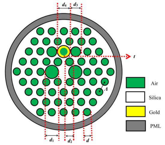
Figure 1.
Cross-sectional schematic of the designed PCF polarization filter.
Two large air holes d1 and d3 are, respectively, set on both sides of the fiber core and the gold-coated hole region, which can effectively increase the asymmetry of the fiber and improve the resonant coupling between the CM and SPM in a single polarization direction. Two slightly enlarged air holes d2 of the proposed filter form a bridge between the two kinds of modes. This setting of this structure can form a strong polarization filter transmission.
The silica is chosen as a substrate material of the presented PCF. The refractive index of silica is subjected to its Sellmeier equation, which is represented by [23]:
here, λ is the light wavelength, and its unit is μm. The Sellmeier coefficients of B1, B2, B3, C1, C2 and C3 are found in Table 1. Using the Sellmerier equation of silica in our simulation analysis, the refractive index of silica varies with wavelength, so the material properties of silica in the designed filter have been considered.

Table 1.
The parameters in the Sellmeier equation.
Gold is used as filling material, and its relative dielectric constant is expressed by using the Drude–Lorentz model [24]:
here, is the high frequency dielectric constant. is a weighting coefficient. is the angular frequency of the light. and are the plasma frequency and damping frequency, respectively. is the frequency of the Lorentz oscillator. is the spectral width of the Lorentz oscillator. The corresponding coefficient parameters of gold are set as shown in Table 2.
Table 2.
The parameters of gold.
During the process of numerical simulation, in order to reduce the radiation loss, the perfectly matched layer and scattering boundary conditions are employed. The dispersion distribution between two kinds of modes are analyzed through the FVFEM-based software. The computation area is discretized with triangular subdomains and meshed with 25,360 number of smallest elements. The CL of the fiber mode is calculated by using the imaginary part of effective refractive index (Im(neff)) [25]:
here, the unit of α(x, y) is dB/cm.
3. Numerical Simulation and Results Analysis
The optimal parameters d1 = 2.40 μm, d2 = 1.38 μm, d3 = 1.80 μm, d4 = 2.20 μm, t = 25.60 nm and t = 55.30 nm are obtained during a time consuming process. Figure 2 shows the loss and Re(neff) of CM and SPM with two different t in the left and right arises, respectively. From Figure 2a, when t is 25.60 nm, the Re(neff) of Y-polarized CM has intersection with that of Y-polarized SPM at 1550 nm, where SPR effect happened due to the phase-matching between them. Furthermore, in the Y-polarized direction, CM and SPM have the same loss, which indicates that complete coupling has occurred [26]. However, the coupling strength of both X-polarized CM and SPM is very low, and the loss spectrum appears flat. The respective losses of both Y and X-polarized CM are 1024.84 and 0.12 dB/cm around 1550 nm with a large loss ratio of 8540.33 in both polarizations. Figure 2b shows that the Re(neff) of Y-polarized CM has intersection with that of Y-polarized SPM at 1310 nm as t is 55.30 nm. Besides, Y-polarized CM has the resonance peak with maximum loss, when a complete coupling between CM and SPM occurs. Similarly, in the X-polarized direction, the coupling is weak and no loss peak appears. The losses of 682.14 and 0.03 dB/cm for the respective Y and X-polarized CMs are achieved at 1310 nm, and the loss ratio is 22,738.
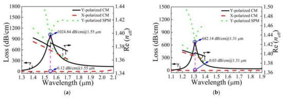
Figure 2.
Loss and the real part of effective refractive index (Re(neff)) of CM and SPM as t is (a) 25.60 nm and (b) 55.30 nm, respectively.
In order to better illustrate the effectiveness of the exhibited structure in increasing loss ratio of the two orthogonal polarization directions, the loss and distribution of the electric field of CM with different values of d3 are analyzed. Figure 3 and Figure 4 show the corresponding distribution of the electric field of Y-polarized CM and the losses of two polarized CM with d3 = 1.40, 1.60, 1.80 μm and d1 = 2.40 μm, d2 = 1.38 μm, d4 = 2.20 μm, t = 25.60 nm. The loss peak wavelength is 1740, 1600 and 1550 nm, respectively. From Figure 3 and Figure 4, as the value of d3 increases, the distance between the gold film hole and the two air holes with d3 decreases, the designed structure can effectively prevent the diffusion of the electromagnetic field intensity from the core to the metal surface, and the energy is concentrated in a certain area of the metal surface. Additionally, the mode coupling method has also changed, that is, the CM is no longer coupled with the second-order SPM, but it is only coupled with a part of the second-order SPM. The energy does not spread to other regions. Therefore, the coupling strength in the Y-polarized direction will be stronger. On the other hand, it effectively blocks the coupling channel between the CM and SPM in the X-polarized direction. Therefore, the intensity of the X-polarized loss decreases as d3 increases. This results in the loss difference and loss ratio of the designed PCF polarization filter being very large.
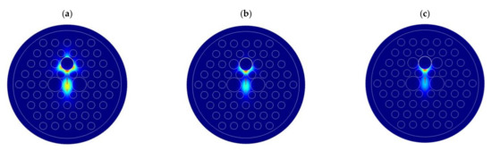
Figure 3.
Distribution of the electric field of Y-polarized CM varied with d3 = (a) 1.40, (b) 1.60, (c) 1.80 μm and d1 = 2.40 μm, d2 = 1.38 μm, d4 = 2.20 μm, t = 25.60 nm.
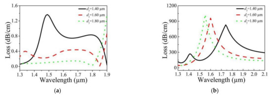
Figure 4.
Loss of (a) X-polarized and (b) Y-polarized CM varied with d3 = 1.40, 1.60, 1.80 μm and d1 = 2.40 μm, d2 = 1.38 μm, d4 = 2.20 μm, t = 25.60 nm.
Figure 5 shows the distribution of the electric field of X-polarized CM, Y-polarized CM, and Y-polarized SPM at 1550 and 1310 nm with the complete coupling between Y-polarized CM and SPM. From Figure 5, whether at 1310 nm or 1550 nm, the distributions of these three kinds of modes are similar. The electromagnetic field intensity of X-polarized CM is confined to the PCF core, while that of Y-polarized CM is transferred to the SPM. Moreover, the electric field distributions of both Y-polarized CM and SPM are essentially the same. That indicates when the light with the wavelength of 1550 nm or 1310 nm is transmitted for a certain distance, the light intensity distribution in Y-polarized direction is attenuated seriously, but the X-polarized light still retains a high energy. Therefore, the single polarization filter is realized.
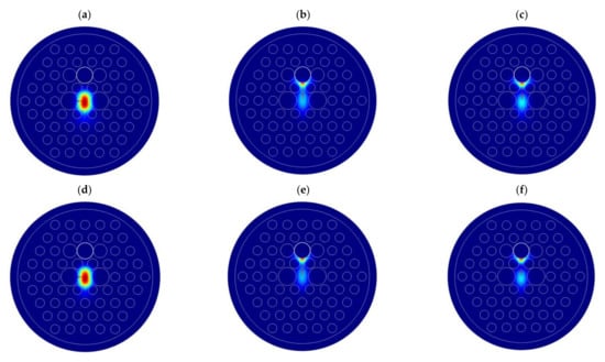
Figure 5.
Distribution of the electric field of (a,d) X-polarized CM, (b,e) Y-polarized CM, and (c,f) Y-polarized SPM at 1550 and 1310 nm as the complete coupling occurs.
In the following section, the analysis results in Figure 6 show that the polarization filter characteristics vary with different d1, d2, d3, d4, and t values. As shown from Figure 6a, the peak wavelength experiences a red shift by increasing d1 from 2.20, 2.40 to 2.60 μm. It should also be noted that the peak intensity of Y-polarized CM increases firstly and then decreases as d1 increases. This is because the further increase of d1 results in the light constrained weakly in the core, which makes the coupling between them weak and the peak intensity reduce. Hence, the peak wavelength and intensity of the loss can be coarsely adjusted by selecting appropriate d1. Figure 6b shows the loss of Y-polarized CM varied with d2 = 1.30, 1.35 and 1.40 μm. From Figure 6b, the peak wavelength decreases from 1850 to 1500 nm by increasing d2 values from 1.30 to 1.40 μm. Furthermore, the peak intensity of Y-polarized CM increases obviously with increasing d2. Therefore, the peak wavelength and intensity can be coarsely tuned with selecting proper d2. Figure 6c shows the loss of Y-polarized CM varied with d3 = 1.60, 1.70 and 1.80 μm. From Figure 6c, the peak wavelength is 1600, 1570 and 1550 nm when d3 is 1.60, 1.70 and 1.80 μm, respectively. Moreover, the peak intensity of Y-polarized CM increases slightly as d3 increases. It can be seen from the above analysis that the peak wavelength and intensity of the loss do not obviously change with the increase of d3. Therefore, the peak wavelength and intensity can be fine-tuned by adjusting d3 appropriately. Figure 6d shows the loss of Y-polarized CM varied with d4 = 2.10, 2.15 and 2.20 μm. From Figure 6d, the peak wavelength of Y-polarized CM shifts to shorter wavelength, that is, from 1780 to 1550 nm with d4 increasing from 2.10 to 2.20 μm. Meanwhile, the peak intensity of Y-polarized CM increases from 846.74 to 1024.84 dB/cm with the increase of d4. Therefore, the peak wavelength and intensity can be coarse adjusted by using the appropriate d4. Figure 6e shows the loss of Y-polarized CM varied with t = 22, 26 and 30 nm. From Figure 6e, the peak wavelength of CM shifts to shorter wavelength with the increase of t, but the movement speed slows down gradually. This is because the Re(neff) of SPM decreases with increasing t, but that of CM does not alter distinctly, which generates the blue-shift of the phase-matching point. Furthermore, the increasing t value decreases the peak intensity of Y-polarized CM. That is why the light has difficulty penetrating it as the gold film is too thick, which makes the coupling between CM and SPM weaken. Therefore, the peak wavelength and intensity of the loss can be roughly adjusted by tuning t properly.
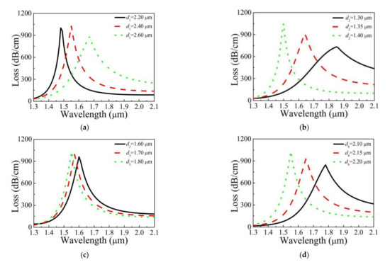
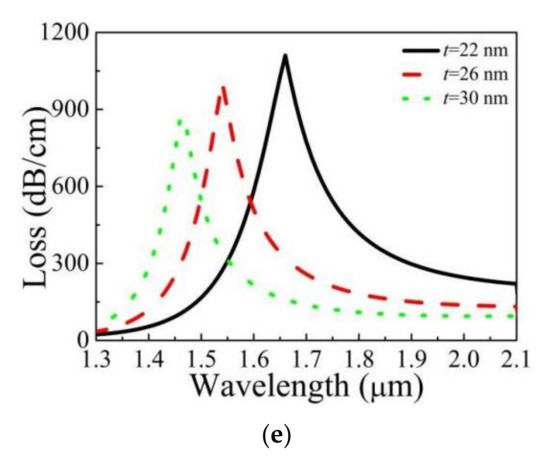
Figure 6.
Loss of Y-polarized CM varied with different (a) d1, (b) d2, (c) d3, (d) d4, and (e) t, and other parameters kept unchanged.
CT is a key indicator to reflect the property of the filters, which determines the effect on the unnecessary polarization mode. The available bandwidth of the filters is defined as a band with a CT value greater than 20 dB or less than −20 dB. The relationship between the CT value and fiber length can be represented by the following formula [27,28]:
here, L is the PCF length. The unit of the CT and L is dB and μm, respectively.
Figure 7 shows the CT value varied with L = 100, 200, and 300 μm as the PCF is arranged with the optimal structural parameters. From Figure 7, it is clear that the CT value reaches to the peak both at 1550 and 1310 nm. As L is increased from 100 to 300 μm, whether at 1550 nm or 1310 nm, both the peak of the CT value and the bandwidth with a CT value greater than 20 dB are increased. The available bandwidth is 280 nm, and the maximum CT value is 89.01 dB at 1550 nm when L is 100 μm in Figure 7a. The CT value is greater than 20 dB in all bands as L is more than 300 μm. From Figure 7b, as L is 100 μm, the available bandwidth is 90 nm, and the maximum CT value is 59.24 dB around 1310 nm. In contrast to the previously reported filter, the presented filter with shorter lengths reveals higher CT value and wider bandwidth. The results show that the designed polarization filter can achieve a strong filtering performance both at the communication wavelength of 1550 and 1310 nm.
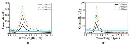
Figure 7.
CT value varied with different L when d1 = 2.40 μm, d2 = 1.38 μm, d3 = 1.80 μm, d4 = 2.20 μm, (a) t = 25.60 nm and (b) t = 55.30 nm.
Figure 8 shows the CT value varied with different d1, d2, d3, d4 and t in the case of L = 100 μm. From Figure 8, the structural parameters have the same influence on the CT as loss value. The CT value has the same change rule as the loss by varying d1. As d2, d3 and d4 increase, the CT value increases. The increase of t causes the CT value to decrease linearly.
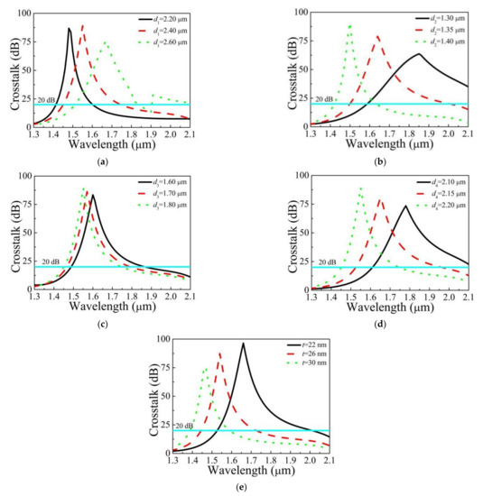
Figure 8.
CT value varied with different (a) d1, (b) d2, (c) d3, (d) d4 and (e) t.
To comprehensively demonstrate the performance of the achieved filter, the comparison between the designed filter and the previously reported filters is made. Table 3 shows the results for resonance wavelength, loss, loss ratio, filter length and bandwidth. The simulation results in Table 3 reveal that the realized loss ratio is 8540.33 and 22,738, and the obtained filtering bandwidth at 1550 and 1310 nm is 640 and 180 nm with a fixed length of 200 μm, respectively. The comparison results show that, whether at 1310 or 1550 nm, the designed PCF polarization filter with more miniaturization realizes a higher loss ratio and wider filtering bandwidth. Therefore, the comparison of many parameters shows that our proposed polarization filter has better performance.
Table 3.
Comparison results between the proposed filter and the previously reported filter.
There are usually two steps to make the proposed hexagonal PCF polarization filter. First of all, the hexagonal PCF is realized based on the improved stack and draw method [29,30]. Secondly, the selective coated gold film in the air hole is carried out by wet chemical deposition, and the gold film thickness can be controlled accurately [4,31]. It is inevitable that the structural parameters change slightly in the process of PCF fabrication. Figure 9 shows the variety of CT value with ±1% tolerances of the main structural parameters. The ±1% deviations of d2 have a small influence on CT value, and ±1% tolerances of d1 and t have no influence. Furthermore, the PCF polarization filter still has a high loss ratio, large CT values and a wide filtering bandwidth under ±1% deviations.
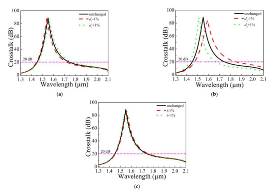
Figure 9.
CT value varied with the ±1% tolerances of (a) d1, (b) d2 and (c) t.
In view of the application of the proposed PCF single polarization filter. The splice loss between the proposed device and the traditional single-mode fibers (SMFs) is considerable. The splice loss of this designed fiber to a SMF with a mode filed diameter (MFD) of 10 μm is around 7.33 dB at 1.55 μm, which can be further controlled either by the splice-free interconnection techniques [32] or using fusion splicing by repeated arc discharges techniques [33]. According to the reference [34], this splice loss can also be overcome if this PCF structure is coupled with the SMF with the MFD less than 10 μm.
For the spatial optical path coupling in the experiment, a laser beam is emitted from the laser, firstly using one lens to collimate, then using another lens to focus, using a high-precision potential shifting platform and other devices to adjust the position of the proposed PCF polarization filter to improve the coupling efficiency of spatial optical path and achieve the mode field matching.
4. Conclusions
A novel gold-coated hexagonal PCF polarization filter with a high loss ratio is proposed and studied. Numerical simulation results show that d1, d2, d4 and t have greater influence on the peak wavelength and intensity of the loss, but d3 has smaller impact on that. The CM and SPM can be completely coupled at the wavelength of 1550 nm in Y-polarized direction, where the respective losses of Y and X-polarized CM are 1024.84 and 0.12 dB/cm with a high loss ratio of 8540.33. Nevertheless, only as t is changed to 55.30 nm, the respective losses of Y and X-polarized CM at 1310 nm are 682.14 and 0.03 dB/cm, and the loss ratio reaches to 22738. The filtering bandwidths with a fixed length of 200 μm at 1550 and 1310 nm are 640 and 180 nm, respectively. The above results also show that the designed PCF polarization filter has larger loss ratio of Y to X-polarized CM, and wider filtering bandwidth with a shorter PCF length. The structure deviation analysis shows that the polarization filter have good fabrication tolerances. Therefore, the designed hexagonal PCF polarization filter will inevitably be extensively put into use in the optical fiber communication system.
Author Contributions
Conceptualization, C.W.; methodology, C.W.; software, C.W.; validation, C.W.; formal analysis, C.W. and G.Z.; investigation, C.W.; resources, C.W.; data curation, C.W; writing—original draft preparation, C.W.; writing—review and editing, Y.Z. (Yajing Zhang) and L.J.; visualization, Z.W. and Y.Z. (Yiyang Zhang); supervision, Z.W., Y.Z. (Yiyang Zhang) and W.B.; project administration, C.W. and L.J.; funding acquisition, C.W. All authors have read and agreed to the published version of the manuscript.
Funding
This research is funded by the National Science Foundation of China (Nos. 61405173, 61405172), National Science Foundation of Hebei Province (Nos. F2018105036, F2019105108, F2019203549, 19941708G, 206Z0401G), Science and Technology Project of Hebei Education Department (No. ZD2021409, ZC2021033), PhD Innovation Fund Project of Tangshan University.
Institutional Review Board Statement
Not applicable.
Informed Consent Statement
Not applicable.
Data Availability Statement
Not applicable.
Acknowledgments
We thank Key Lab of Intelligent Data Information Processing and Control of Hebei Province and Key Lab of Intelligent Motion Control System of Tangshan City (Intelligence and Information Engineering College) for the scientific helps and supports throughout this research.
Conflicts of Interest
The authors declare no conflict of interest.
References
- Schmidt, M.A.; Russell, P.S.J. Long-range spiralling surface plasmon modes on metallic nanowires. Opt. Express 2008, 16, 13617–13623. [Google Scholar] [CrossRef]
- Otupiri, R.; Akowuah, E.K.; Haxha, S.; Ademgil, H.; AbdelMalek, F.; Aggoun, A. A Novel Birefrigent Photonic Crystal Fiber Surface Plasmon Resonance Biosensor. IEEE Photon. J. 2014, 6, 6801711. [Google Scholar] [CrossRef]
- Zhao, Y.; Deng, Z.Q.; Li, J. Photonic crystal fiber based surface plasmon resonance chemical sensors. Sens. Actuators B Chem. 2014, 202, 557–567. [Google Scholar] [CrossRef]
- Zhang, X.; Wang, R.; Cox, F.M.; Kuhlmey, B.T.; Large, M.C.J. Selective coating of holes in microstructured optical fiber and its application to in-fiber absorptive polarizers. Opt. Express 2007, 15, 16270–16278. [Google Scholar] [CrossRef]
- Khaleque, A.; Hattori, H.T. Polarizer based upon a plasmonic resonant thin layer on a squeezed photonic crystal fiber. Appl. Opt. 2015, 54, 2543–2549. [Google Scholar] [CrossRef] [PubMed]
- Zhang, S.Y.; Yu, X.; Zhang, Y.; Shum, P.; Zhang, Y.T.; Xia, L.; Liu, D.M. Theoretical Study of Dual-Core Photonic Crystal Fibers with Metal Wire. IEEE Photon. J. 2012, 4, 1178–1187. [Google Scholar] [CrossRef]
- An, G.W.; Li, S.G.; Zhang, W.; Fan, Z.K.; Bao, Y.J. A polarization filter of gold-filled photonic crystal fiber with regular triangular and rectangular lattices. Opt. Commun. 2014, 331, 316–319. [Google Scholar] [CrossRef]
- Wang, H.Y.; Yan, X.; Li, S.G.; An, G.W.; Zhang, X.N.; Yuan, Z.Y. Design of the polarization filter based on photonic crystal fiber with Au-coated air holes. Opt. Quant. Electron. 2016, 48, 512. [Google Scholar] [CrossRef]
- Shi, M.; Li, S.G.; Chen, H.L.; Wang, G.Y.; Zhao, Y.Y. Surface plasmon resonance effect induced tunable polarization filter based on gold film selectively coated photonic crystal fiber. Opt. Commun. 2017, 396, 257–260. [Google Scholar] [CrossRef]
- Hossen, M.N.; Ferdous, M.; Ahmed, K.; Khalek, M.A.; Chakma, S.J.; Paul, B.K. Single polarization photonic crystal fiber filter based on surface plasmon resonance. Front. Optoelectron. 2019, 12, 157–164. [Google Scholar] [CrossRef]
- Qu, Y.W.; Yuan, J.H.; Zhou, X.; Li, F.; Mei, C.; Yan, B.B.; Wu, Q.; Wang, K.R.; Sang, X.Z.; Long, K.P.; et al. A V-shape photonic crystal fiber polarization filter based on surface plasmon resonance effect. Opt. Commun. 2019, 452, 1–6. [Google Scholar] [CrossRef]
- Kuhlmey, B.T.; Pathmanandavel, K.; McPhedran, R.C. Multipole analysis of photonic crystal fibers with coated inclusions. Opt. Express 2006, 14, 10851–10864. [Google Scholar] [CrossRef]
- Lee., H.W.; Schmidt, M.A.; Tyagi, H.K.; Sempere, L.P.; Russell, P.S.J. Polarization-dependent coupling to plasmon modes on submicron gold wire in photonic crystal fiber. Appl. Phy. Lett. 2008, 93, 111102. [Google Scholar] [CrossRef]
- Nagasaki, A.; Saitoh, K.; Saitoh, M. Polarization characteristics of photonic crystal fibers selectively filled with metal wires into cladding air holes. Opt. Express 2011, 19, 3799–3808. [Google Scholar] [CrossRef] [PubMed]
- Xue, J.R.; Li, S.G.; Xiao, Y.Z.; Qin, W.; Xin, X.J.; Zhu, X.P. Polarization filter characters of the gold-coated and the liquid filled photonic crystal fiber based on surface plasmon resonance. Opt. Express 2013, 21, 13733–13740. [Google Scholar] [CrossRef] [PubMed]
- Liu, Q.; Li, S.G.; Li, H.; Zi, J.C.; Zhang, W.; Fan, Z.K.; An, G.W.; Bao, Y.J. Broadband Single-Polarization Photonic Crystal Fiber Based on Surface Plasmon Resonance for Polarization Filter. Plasmonics 2015, 10, 931–939. [Google Scholar] [CrossRef]
- Dou, C.; Jing, X.L.; Li, S.G.; Liu, Q.; Bian, J. A Photonic Crystal Fiber Polarized Filter at 1.55 μm based on Surface Plasmon Resonance. Plasmonics 2016, 11, 1163–1168. [Google Scholar] [CrossRef]
- Wang, X.Y.; Li, S.G.; Liu, Q.; Wang, G.Y.; Zhao, Y.Y. Design of a Single-Polarization Single-Mode Photonic Crystal Fiber Filter Based on Surface Plasmon Resonance. Plasmonics 2017, 12, 1325–1330. [Google Scholar] [CrossRef]
- Wang, Y.J.; Li, S.G.; Chen, H.L.; Shi, M.; Liu, Y.C. Ultra-wide bandwidth polarization filter based on gold-coated photonic crystal fiber around the wavelength of 1.55 μm. Opt. Laser Technol. 2018, 106, 22–28. [Google Scholar] [CrossRef]
- Lu, X.L.; Chang, M.; Chen, N.; Zhang, X.D.; Zhuang, S.L.; Xu, J. Design of a Metal-Filled Photonic-Crystal Fiber Polarization Filter Based on Surface Plasmon Resonance at 1.31 and 1.55 µm. IEEE Photon. J. 2018, 10, 7203913. [Google Scholar] [CrossRef]
- Zhao, X.T.; Hua, L.; Jiang, G.H.; Cheng, J.R.; Xiong, Q. A Novel Polarization Filter Based on Photonic Crystal Fiber with a Single Au-Coated Air Hole and Semi-Hourglass Structure. Plasmonics 2019, 14, 1725–1733. [Google Scholar] [CrossRef]
- Zhang, Y.X.; Yuan, J.H.; Qu, Y.W.; Zhou, X.; Yan, B.B.; Wu, Q.; Wang, K.R.; Sang, X.Z.; Long, K.P.; Yu, C.X. Design of diamond-shape photonic crystal fiber polarization filter based on surface plasma resonance effect. Chin. Phys. B 2020, 29, 034208. [Google Scholar] [CrossRef]
- Ghosh, G.; Endo, M.; Iwasaki, T. Temperature-Dependent Sellmeier Coefficients and Chromatic Dispersions for Some Optical Fiber Glasses. J. Lightwave Technol. 1994, 12, 1338–1342. [Google Scholar] [CrossRef] [Green Version]
- Islam, M.S.; Sultana, J.; Rifat, A.A.; Ahmed, R.; Dinovitser, A.; Brian, W.H.N.; Heike, E.H.; Abbott, D. Dual-polarized highly sensitive plasmonic sensor in the visible to near-IR spectrum. Opt. Express 2018, 26, 30347–30361. [Google Scholar] [CrossRef] [PubMed]
- Sun, B.; Chen, M.Y.; Zhou, J.; Zhang, Y.K. Surface Plasmon Induced Polarization Splitting Based on Dual-Core Photonic Crystal Fiber with Metal Wire. Plasmonics 2013, 8, 1253–1258. [Google Scholar] [CrossRef]
- Zhang, Z.H.; Shi, Y.F.; Bian, B.M.; Lu, J. Dependence of leaky mode coupling on loss in photonic crystal fiber with hybrid cladding. Opt. Express 2008, 16, 1915–1922. [Google Scholar] [CrossRef]
- Florous, N.; Saitoh, K.; Koshiba, M. A novel approach for designing photonic crystal fiber splitters with polarization-independent propagation characteristics. Opt. Express 2005, 13, 7365–7373. [Google Scholar] [CrossRef]
- Chen, L.; Zhang, W.G.; Zhang, Z.; Liu, Y.J.; Sieg, J.; Zhang, L.Y.; Zhou, Q.; Wang, L.; Wang, L.; Yan, T.Y. Design for a Single-Polarization Photonic Crystal Fiber Wavelength Splitter Based on Hybrid-Surface Plasmon Resonance. IEEE Photon. J. 2014, 6, 1–9. [Google Scholar]
- Mahdiraji, G.A.; Chow, D.M.; Sandoghchi, S.R.; Amirkhan, F.; Dermosesian, E.; Yeo, K.S.; Kakael, Z.; Ghomeishi, M.; Poh, S.Y.; Gang, S.Y.M.; et al. Challenges of solutions in fabrication of silica-based photonic crystal fibers: An experimental study. Fiber Integr. Opt. 2014, 33, 85–104. [Google Scholar] [CrossRef]
- Wang, Y.; Huang, Q.; Zhu, W.J.; Yang, M.H.; Lewis, E. Novel optical fiber SPR temperature sensor based on MMF-PCF-MMF structure and gold-PDMS film. Opt. Express 2018, 26, 1910–1917. [Google Scholar] [CrossRef]
- Liu, B.; Jiang, Y.; Zhu, X.; Tang, X.; Shi, Y. Hollow fiber surface plasmon resonance sensor for the detection of liquid with high refractive index. Opt. Express 2013, 21, 32349–32357. [Google Scholar] [CrossRef] [PubMed]
- Leon-Saval, S.G.; Birks, T.A.; Joly, N.Y.; George, A.K.; Wadsworth, W.J.; Kakarantzas, G. Splice-free interfacing of photonic crystal fibers. Opt.Lett. 2005, 30, 1629–1631. [Google Scholar] [CrossRef] [PubMed]
- Xiao, L.M.; Jin, W.; Demokan, M.S. Fusion splicing small-corephotonic crystal fibers and single-mode fibers by repeated arc discharges. Opt. Lett. 2007, 32, 115–117. [Google Scholar] [CrossRef] [PubMed] [Green Version]
- Asiful Islam, M.; Shah Alam, M. Design Optimization of Equiangular Spiral Photonic Crystal Fiber for Large Negative Flat Dispersion and High Birefringence. J. Lighwave Technol. 2012, 30, 3545–3551. [Google Scholar] [CrossRef]
Publisher’s Note: MDPI stays neutral with regard to jurisdictional claims in published maps and institutional affiliations. |
© 2021 by the authors. Licensee MDPI, Basel, Switzerland. This article is an open access article distributed under the terms and conditions of the Creative Commons Attribution (CC BY) license (https://creativecommons.org/licenses/by/4.0/).