Article

Synchronization of Mutually Delay-Coupled Quantum Cascade Lasers with Distinct Pump Strengths

1
Université Libre de Bruxelles, Optique Nonlinéaire Théorique, Campus Plaine, C.P. 231, 1050 Bruxelles, Belgium
2
Institute of Photonics Integration, Eindhoven University of Technology, P.O. Box 513, 5600MB Eindhoven, The Netherlands
*
Author to whom correspondence should be addressed.
These authors contributed equally to this work.
Photonics 2019, 6(4), 125; https://doi.org/10.3390/photonics6040125
Submission received: 25 October 2019 / Revised: 25 November 2019 / Accepted: 5 December 2019 / Published: 10 December 2019
(This article belongs to the Special Issue Semiconductor Laser Dynamics: Fundamentals and Applications)

Abstract

:
The rate equations for two delay-coupled quantum cascade lasers are investigated analytically in the limit of weak coupling and small frequency detuning. We mathematically derive two coupled Adler delay differential equations for the phases of the two electrical fields and show that these equations are no longer valid if the ratio of the two pump parameters is below a critical power of the coupling constant. We analyze this particular case and derive new equations for a single optically injected laser where the delay is no longer present in the arguments of the dependent variables. Our analysis is motivated by the observations of Bogris et al. (IEEE J. Sel. Top. Quant. El. 23, 1500107 (2017)), who found better sensing performance using two coupled quantum cascade lasers when one laser was operating close to the threshold.

1. Introduction

Compact quantum cascade lasers (QCLs) emitting in the midwave infrared (mid-IR) are the leading semiconductor laser sources for such applications as absorption spectroscopy in the molecular fingerprint region [1,2]. Mid-IR spectroscopy has led to new applications in biology and medicine such as breath analysis, the investigation of serum, noninvasive glucose monitoring in bulk tissue, and the combination of spectroscopy and microscopy of tissue thin sections for rapid histopathology [3]. Other applications include environmental sensing and pollution monitoring, industrial process control, and security [4,5].
Recently, a novel gas sensor relying on a pair of mutually injecting QCLs has been analyzed both experimentally and numerically [6,7,8]. The sensing performances of the coupled QCLs have been examined in terms of the injection power, bias currents of the lasers, and their spectral detuning. High sensitivity is observed if one of the two lasers is biased around the threshold. The main objective of this paper is to explain these observations by analyzing the rate equations appropriate for two coupled QCLs. As we shall demonstrate, allowing one laser to operate close to its threshold contributes to larger domains of stable phase locked states. Physically, the transient response of the intensity of one laser slows down near its threshold, while the intensity of the second laser is keeping its fast time scale. Consequently, the fast laser quickly approaches a quasi-steady state regime, and the long time dynamics of the laser system is controlled by the slow laser. In other words, the coupled QCLs is becoming an injected laser problem where the fast and slow lasers are acting as master and slave, respectively. In a different setting, two coupled QCL cavities separated by a gap of 3 μ m were studied as a monolithic integrated photodetector [9]. An integrated detector is used for spatial sensing of the light intensity, and its control is again achieved by changing the applied bias.
The dynamics of two mutually delay-coupled semiconductor lasers (SLs), in a face-to-face configuration, has been a topic of active research [10,11,12,13,14]. The time delay results from the finite propagation time of the light from one laser to the other one. Of primary interest are the conditions for stable locking, and systematic studies have been undertaken in order to explore the effects of key parameters. These led to striking comparisons between experimental and numerical bifurcation diagrams [15,16,17,18,19,20,21]. Most often, the time delay is relatively large compared to the photon lifetime (21 to a 51 mm gap between the lasers) [16,17,18]. However, systems of two coupled lasers in photonic integrated circuits have recently been investigated (1–2 mm gap) [11,12]. They revive previous theoretical investigations of the short coupling regime [22].
In a different optical setting, two laterally coupled semiconductor lasers (no delay) also raised the interest of researchers for the presence of exceptional points (EPs) in parameter space [23,24,25]. An EP is a point where two (or more) eigenvalues simultaneously coalesce. One key difference between EPs and conventional degeneracies is their higher sensitivity to perturbations. This particular property of EPs has been proposed for use in sensor applications [26,27].
QCLs, based on intersubband transitions in semiconductor quantum wells, are characterized by ultrafast (picosecond) carrier lifetimes. An important consequence of this unique property is the absence of relaxation oscillations (RO) in the transient response of these devices. For conventional interband diode lasers (IDLs), the ROs are generating undesirable intensity oscillations for quite low feedback amplitudes. By contrast, dynamical instabilities for QCLs are only possible if the delayed feedback is strong enough [28,29].
For two coupled lasers operating at close, but distinct optical frequencies, the desired regime is when the lasers operate in a continuous wave (CW) with their frequency and phase mutually locked. They are called one color states [30] or compound laser modes (CLMs) [19,22]. To the best of our knowledge, phase locked states of two delay-coupled SLs have been investigated theoretically with equal or nearly equal pump parameters. However, the individual laser pump rates are experimentally controlled variables, and the effects of unequal pumps have been studied for two SLs without delays [23,24,25,26,27,31].
The organization of the paper is as follows. Section 2 introduces the rate equations for two coupled QCLs, as well as their asymptotic approximation, valid in the limit of weak coupling, weak frequency detuning, and arbitrary pump parameters. It consists of two delay coupled Adler equations for the phases of the fields. The CLMs are then investigated in Section 3 in terms of their frequencies. As functions of the detuning, these frequencies appear as close orbits in the bifurcation diagram. As the pump parameter of one laser comes close to threshold ( P 2 0 ) , these orbits overlap progressively larger domains of detuning. In Section 4, the limit P 2 / P 1 0 is analyzed in detail taking into account that our problem now depends on two small parameters, namely P 2 / P 1 and the small coupling rate. A new asymptotic analysis of the original laser equations is performed and leads to equations for an optically injected single mode laser where the delay no longer appears in the arguments of the dependent variables. The stability of the locked states is then analyzed. If one laser is operating slightly below the threshold, as in the experiments in [7], the locked state is always stable. Last, we discuss in Section 5 the impact of our results for conventional IDL lasers.

2. Dimensionless Equations

The response of a QCL subject to a delayed feedback is analyzed using rate equations formulated in [32,33,34] on the basis of a three level model. In [28], it was shown that these equations for a QCL subject to delayed optical feedback can be reduced to the classical Lang and Kobayashi (LK) equations derived for IDLs. The LK equations consist of the rate equations for a conventional SL supplemented by a term describing the optical feedback of the electrical field. Two key parameters control the dynamical stability of the laser, namely the ratio of the carrier to photon lifetimes T and the linewidth enhancement factor α . For a QCL, T is typically an O ( 1 ) quantity compared to the large O ( 10 3 ) value of an IDL. Moreover, α = 0 1 for a QCL is relatively small compared to the IDL α = 2.5 3.5 . These two essential properties of a QCL explain the observed high tolerance with respect to optical feedback. Mathematically, we therefore consider two coupled LK equations as the rate equations for two QCLs coupled face-to-face. We use the formulation detailed in [19]. Specifically, the evolution equations are in terms of the optical fields E j o p t = R j exp ( i ϕ j + i ω j t ) where ω j is the optical angular frequency of laser j and the carrier densities N j ( j = 1 , 2 ) . Introducing the frequency detuning Δ = ω 2 ω 1 and the averaged frequency ω ¯ = ( ω 1 + ω 2 ) / 2 , ϕ 1 = Δ t / 2 + Φ 1 , and ϕ 2 = Δ t / 2 + Φ 2 , it is mathematically convenient to reformulate the two fields as:
E 1 o p t = R 1 exp ( i Δ t 2 + i Φ 1 + i ω 1 t ) = R 1 exp ( i Φ 1 + i ω ¯ t ) ,
E 2 o p t = R 2 exp ( i Δ t 2 + i Φ 2 + i ω 2 t ) = R 2 exp ( i Φ 2 + i ω ¯ t ) .
The rate equations for the amplitudes R j , phases Φ j , and densities N j are then given by [31]
R 1 = N 1 R 1 + ε R 2 ( t τ ) cos ( θ + Φ 2 ( t τ ) Φ 1 C ) ,
Φ 1 = Δ 2 + α N 1 + ε R 2 ( t τ ) R 1 sin ( θ + Φ 2 ( t τ ) Φ 1 C ) ,
T N 1 = P 1 N 1 ( 1 + 2 N 1 ) R 1 2 ,
R 2 = N 2 R 2 + ε R 1 ( t τ ) cos ( θ + Φ 1 ( t τ ) Φ 2 C ) ,
Φ 2 = Δ 2 + α N 2 + ε R 1 ( t τ ) R 2 sin ( θ + Φ 1 ( t τ ) Φ 2 C ) ,
T N 2 = P 2 N 2 ( 1 + 2 N 2 ) R 2 2 .
In these equations, time t is measured in units of the photon lifetime τ p 10 11 s . Prime means differentiation with respect to t. P 1 = O ( 1 ) and P 2 = O ( 1 ) are the pump parameters measuring the amount of electrical current used to activate the individual lasers. The complex mutual coupling is accounted for by ε exp ( i θ ) . τ and C ω ¯ τ represent the delay time and the (mean) induced phase, respectively. The distance L between the lasers is a few centimeters, which then implies that the delay τ ( L / c ) / τ p , where c is the speed of light, is around 10 . From Equation (3) with R 1 = O ( 1 ) and R 2 = O ( 1 ) , we note that N 1 needs to be an O ( ε ) small quantity in order to balance the first two terms in the right hand side of Equation (3). Similarly, balancing all three terms in the right hand side of Equation (4) requires that the detuning | Δ | is small like ε . The same conclusions apply for Equations (6) and (7).
We analyze Equations (3)–(8) assuming weak coupling ( ε < < 1 ) and small detuning ( Δ = O ( ε ) ) . The analysis leads to the following two coupled Adler delay differential equations for the phase of the electrical fields (see Section 1 of the Supplementary File):
d Φ 1 d t = Δ 2 + ε P 2 P 1 ( 1 + α 2 ) sin ( θ 0 + Φ 2 ( t τ ) Φ 1 ) ,
d Φ 2 d t = Δ 2 + ε P 1 P 2 ( 1 + α 2 ) sin ( θ 0 + Φ 1 ( t τ ) Φ 2 )
where
θ 0 θ C arctan ( α ) .
These equations were formulated in [8], using the theory developed in [31] for the zero delay case. They were also the starting point of the investigations in [35]. We mathematically rederived those equations in a more systematic way by using an asymptotic method where Δ is scaled with respect to ε . This analysis is necessary as we later consider the case of one laser operating close to its threshold for which Equations (9) and (10) are no longer valid.
Equations (9) and (10) with P 1 = P 2 and θ 0 = 0 have been studied in detail [15,36,37]. Particular attention has been devoted to (1) constant phase solutions ( Φ 1 , Φ 2 ) = ( 0 , σ ) [36], (2) compound laser modes ( Φ 1 , Φ 2 ) = ( ω t , ω t + σ ) [19,36], and (3) time-periodic unbounded solutions ( Φ 1 , Φ 2 ) = ( C / 2 + Φ ( t ) , C / 2 + Φ ( t ) ) with < d Φ / d t > = c s t [15].
It is worthwhile to briefly review the case of zero delay, which was analyzed in detail [38,39,40] since the pioneering work of Winful and Wang [41], who considered the case of zero detuning ( Δ = 0 ) , equal pumps ( P 1 = P 2 ) , coupling phase θ = π / 2 , and - α replacing α in Equations (4) and (7). If τ = 0 , Equations (9) and (10) can be combined into a single equation for σ Φ 2 Φ 1 given by:
d σ d t = Δ + ε 1 + α 2 P 1 P 2 sin ( θ 0 σ ) P 2 P 1 sin ( θ 0 + σ ) .
The steady states are the phase locked states. They are shown in Figure 1 for equal and non-equal pump values. We observe that the size of the locking domain increases as one of the pumps comes closer to its threshold, a feature for which we again see if the delay is not zero.

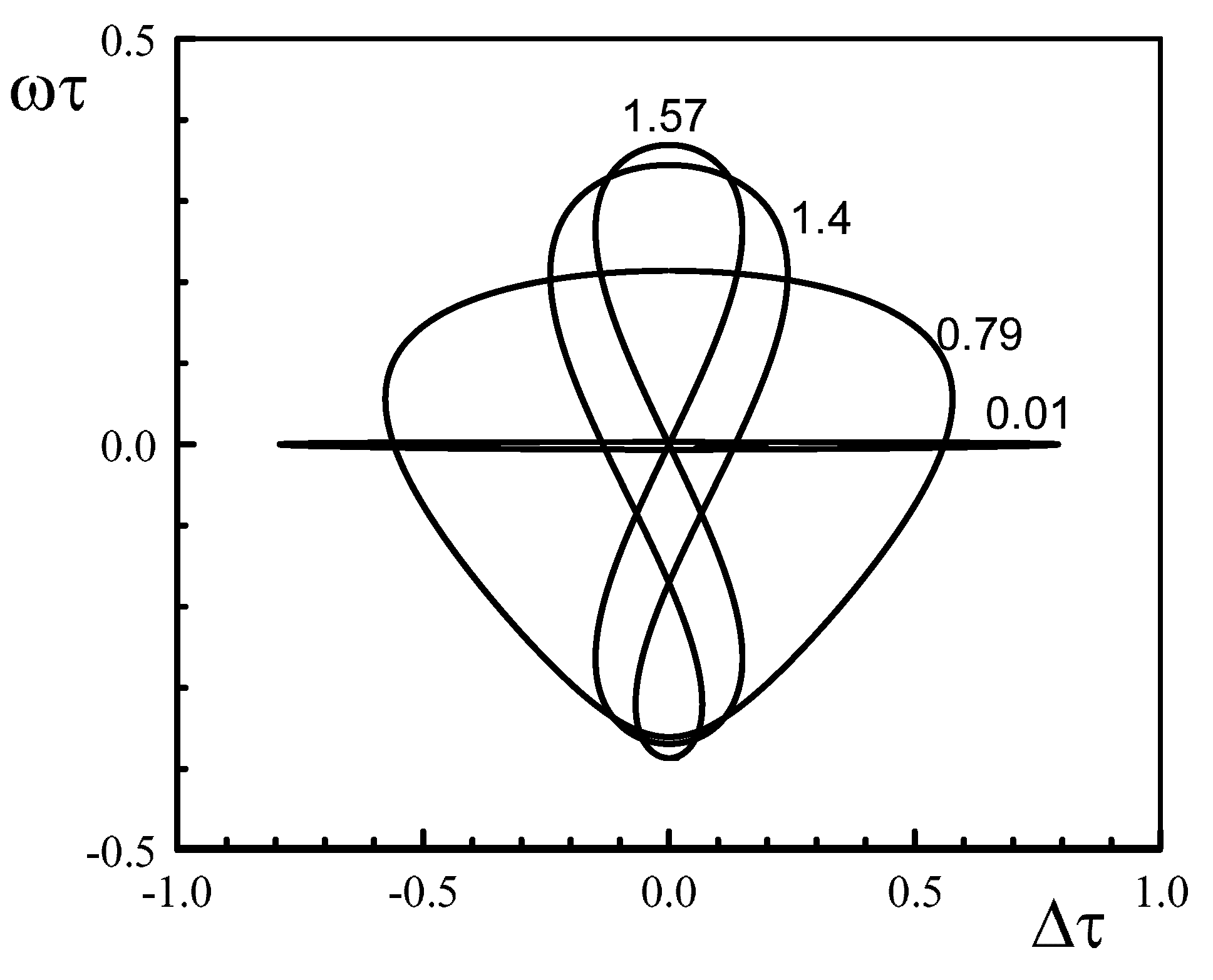
3. Compound Laser Modes

The compound laser modes or CLMs are the basic solutions of our problem. They are the solutions of Equations (9) and (10) of the form:
Φ 1 = ω t , Φ 2 = ω t + σ .
From Equations (1) and (2), we understand that after coupling, the optical frequency ω o p is given by:
ω o p = ω ¯ + ω .
Inserting Equation (13) into Equations (9) and (10) leads to two equations for ω and σ given by:
ω = Δ 2 + ε P 2 P 1 ( 1 + α 2 ) sin ( θ 0 ω τ + σ ) ,
ω = Δ 2 + ε P 1 P 2 ( 1 + α 2 ) sin ( θ 0 ω τ σ ) .
Expanding the trigonometric functions, Equations (15) and (16) are rewritten as:
ω + Δ 2 1 ε P 2 P 1 ( 1 + α 2 ) = sin ( θ 0 ω τ ) cos ( σ ) + cos ( θ 0 ω τ ) sin ( σ ) ,
ω Δ 2 1 ε P 1 P 2 ( 1 + α 2 ) = sin ( θ 0 ω τ ) cos ( σ ) cos ( θ 0 ω τ ) sin ( σ ) .
From Equations (17) and (18), we determine cos ( σ ) and sin ( σ ) :
cos ( σ ) = 1 2 sin ( θ 0 ω τ ) ε ( 1 + α 2 ) ω + Δ 2 P 1 P 2 + ω Δ 2 P 2 P 1 ,
sin ( σ ) = 1 2 cos ( θ 0 ω τ ) ε ( 1 + α 2 ) ω + Δ 2 P 1 P 2 ω Δ 2 P 2 P 1 .

3.1. Equal Pumps

Before we consider the effect of unequal pump parameters, it is worthwhile to first analyze the case of equal pumps. The expression Equations (19) and (20) are considerably simplified as:
cos ( σ ) = ω sin ( θ 0 ω τ ) ε ( 1 + α 2 ) ,
sin ( σ ) = Δ 2 cos ( θ 0 ω τ ) ε ( 1 + α 2 )
and provide a solution in parametric form. We first extract σ = σ ( ω ) from Equation (21):
σ = arccos ω sin ( θ 0 ω τ ) ε ( 1 + α 2 )
and then compute Δ = Δ ( ω ) using Equation (22):
Δ = 2 cos ( θ 0 ω τ ) ε ( 1 + α 2 ) sin ( σ ) .
If τ = 0 , the expression Equation (24) tells us that the locking domain verifies the inequality:
| Δ | 2 ε ( 1 + α 2 ) cos ( θ 0 ) .
The expression Equation (25) is in agreement with Equation (36) in [31]. Figure 2 represents ω τ and σ as functions of Δ τ . The values of the dimensionless parameters are based on the following values of the original parameters for the photon lifetime τ p h , the delay τ e , the feedback rate ε e , and the detuning | Δ e | : τ p h = 7.5 × 10 12 s , τ e = 10 10 s , ε e = 2.8 × 10 9 s 1 , and 0 < | Δ e | 2 π 10 9 s 1 . The dimensionless parameters are then obtained as τ τ e / τ p h = 13.33 , ε ε e × τ p h = 0.021 , and | Δ | | Δ e | × τ p h 0.047 .
Figure 3 shows ω τ as a function of Δ τ for different values of θ 0 . The different orbits are bounded by limit points located at Δ τ = ± Δ τ L P . These points mark the extreme detuning values where the two coupled lasers lock to each other. Figure 4 shows Δ τ L P > 0 as a function of θ 0 for the interval 0 θ 0 π . Δ τ L P is the largest at θ 0 = 0 and π . It motivates examining the limit θ 0 0 . Figure 3 with θ 0 = 0.01 suggests that the nearly flat CLM orbit is bounded by two limit points appearing close to ω τ = 0 . Therefore, the locking condition Equation (25) evaluated at θ 0 = 0 applies for this case.

3.2. Unequal Pumps

We are now ready to explore the case of unequal pumps. Using Equations (19) and (20), we eliminate the trigonometric functions of σ and obtain the following equation for ω :
1 sin 2 ( θ 0 ω τ ) ω P 1 P 2 + P 2 P 1 + Δ 2 P 1 P 2 P 2 P 1 2 + 1 cos 2 ( θ 0 ω τ ) ω P 1 P 2 P 2 P 1 + Δ 2 P 1 P 2 + P 2 P 1 2 = 4 ε 2 ( 1 + α 2 ) .
Equation (26) is equivalent to a quadratic equation for Δ given by:
Δ 2 4 F 2 C 1 + F + 2 C 2 + Δ ω F + F ( C 1 + C 2 ) + ω 2 ( F + 2 C 1 + F 2 C 2 ) 4 ε 2 ( 1 + α 2 ) = 0
where:
F ± P 1 P 2 ± P 2 P 1 , C 1 1 sin 2 ( θ 0 ω τ ) , and C 2 1 cos 2 ( θ 0 ω τ ) .
We only need to explore the domain 0 θ 0 π since C 1 and C 2 remain unchanged with ω τ replacing ω τ and θ 1 = 2 π θ 0 replacing θ 0 . Figure 5 illustrates the case of small values of P 2 / P 1 . The CLM orbits are now close to the line ω τ = Δ τ / 2 and are bounded by two critical values of ω τ = ω ± τ . They delimit the domain of real solutions of the quadratic Equation (27). We note that the CLM orbit increases in size as P 2 / P 1 0 . An analysis of the discriminant of Equation (27) allows us to determine ω ± τ ( see Section 2 of the Supplementary Materials File). They delimit the domain of real solutions for Δ = Δ ( ω ) . Note that they are not the values of ω τ corresponding to the limits points ± Δ τ L P , but are very close if P 2 / P 1 0 . Figure 6 shows ω ± τ as functions of P 2 / P 1 . In implicit form, x P 2 / P 1 = x ( ω τ ) satisfies the quadratic equation:
x 2 + x 2 cos ( 2 ( θ 0 ω τ ) ) 4 ω 2 ε 2 ( 1 + α 2 ) + 1 = 0 .
As seen in Figure 6, | ω ± τ | as x 0 . From Equation (29) and assuming ω 2 = O ( x 1 ) , we find the limit:
ω ± τ ± ε τ 2 ( 1 + α 2 ) P 1 P 2 as x 0 .
The corresponding values of Δ τ are given by Δ τ ± = 2 ω ± . Therefore, the size of the CLM orbits satisfies the inequality:
| Δ | ε ( 1 + α 2 ) P 1 P 2 , ( P 2 / P 1 0 )
Moreover, solving the quadratic Equation (27) and then taking the limit P 2 / P 1 0 lead to:
Δ 2 ω ± 4 P 2 P 1 4 C 1 C 2 ω + ω ( ω ω ) .
In summary, we have determined the CLMs and their limits as P 2 / P 1 0 . Because of the square roots in Equation (28), the ratio P 2 / P 1 needs to be positive. Therefore, we cannot explore the case of Laser 2 slightly below the threshold, and a different asymptotic analysis is needed where the ratio P 2 / P 1 is scaled with respect to ε .
We did not analyze the stability of the CLMs for arbitrary values of the pump parameters. However, we know that, because of the absence of relaxation oscillations, Hopf bifurcation instabilities are possible only for large delays [28,29]. This is not the case here. In the limit P 2 / P 1 small, we note from Equations (9) and (10) that | Φ 1 | freely increases while Φ 2 satisfies a single Adler equation. In Section 3 of the Supplementary Material File, we show that a Hopf bifurcation is not possible. Branches of CLMs are either stable or unstable, and their changes of stability occur at the limit points Δ τ L P (saddle node bifurcation points).

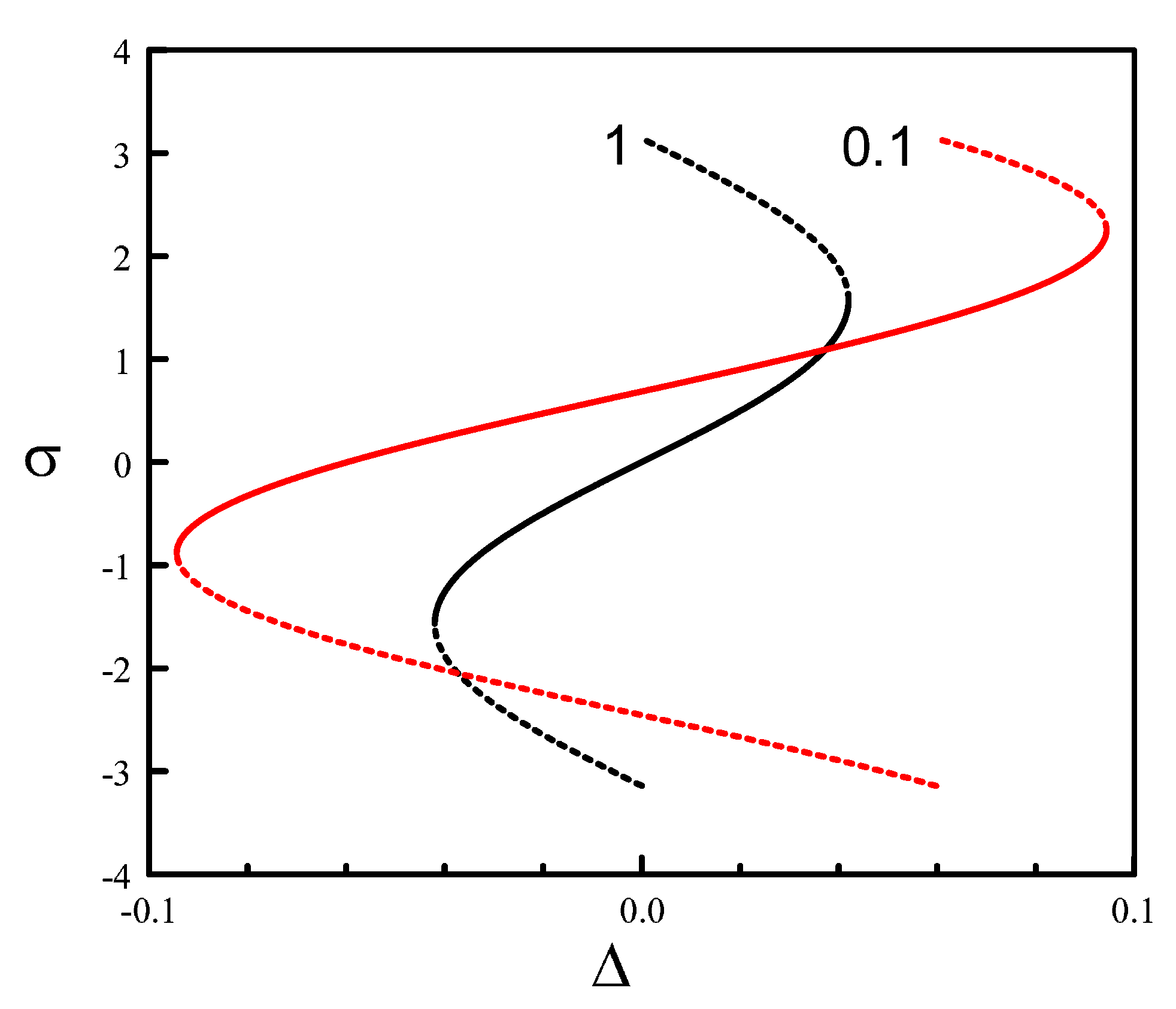
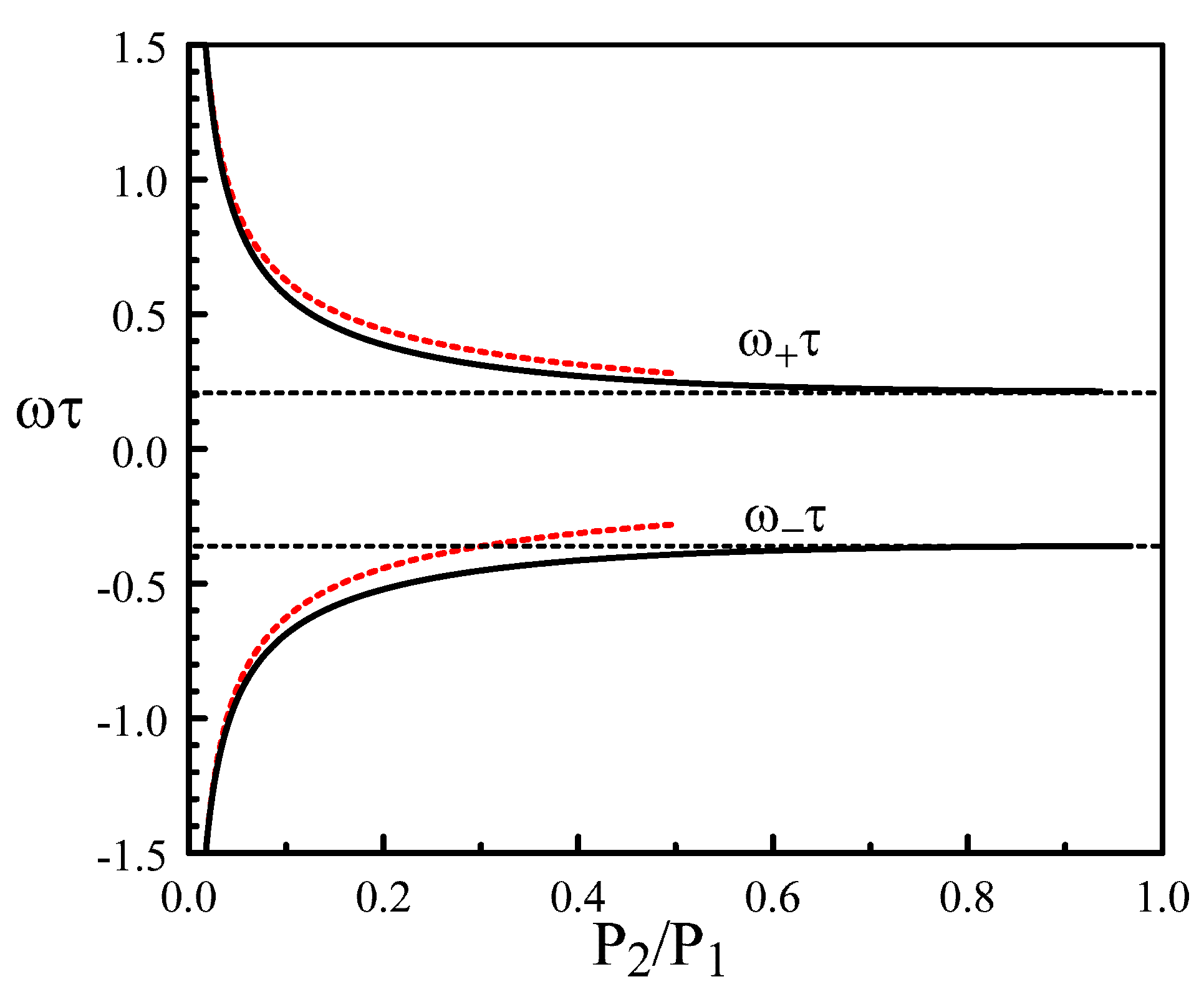
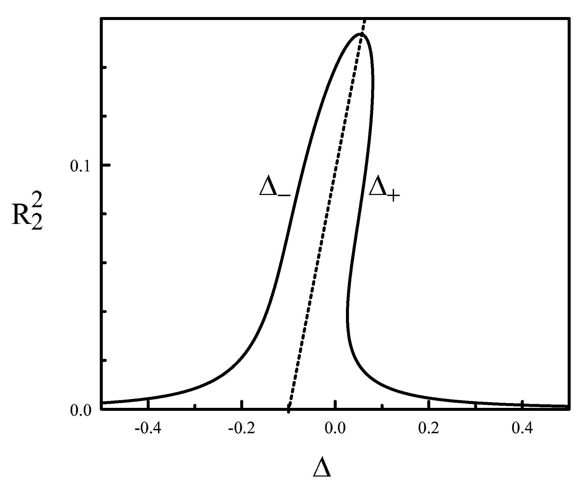
4. The Limit of Small Ratios of the Two Pumps

In Section 4 of the Supplementary File, we examine the limit P 2 / P 1 0 + and find that our previous theory becomes invalid as soon as:
P 2 = O ( ε 2 / 3 ) .
In other words, the two coupled phase Equations (9) and (10) failed to describe the correct dynamics of the mutually injected lasers if P 2 is comparable to ε 2 / 3 or smaller. Section 4 of the Supplementary Material File describes a new asymptotic analysis taking into account the scaling Equation (33). We find R 1 = P 1 and Φ 1 = Δ 2 t , in the first approximation, while R 2 and Φ ¯ 2 Φ 2 + Δ 2 t satisfy the equations for an optically injected laser:
d R 2 d t = ( P 2 R 2 2 ) R 2 + ε P 1 cos ( θ 1 Φ ¯ 2 ) ,
d Φ ¯ 2 d t = Δ + α ( P 2 R 2 2 ) + ε P 1 R 2 sin ( θ 1 Φ ¯ 2 )
where:
θ 1 θ + Δ 2 τ ω 1 τ .
The delay τ does not explicitly appear in the arguments of the dependent variables, but its effect appears in the expression of θ 1 . Using Equations (1) and (2), the leading expressions of the optical fields are:
E 1 o p t = P 1 exp ( i ω 1 t ) and E 2 o p t = R 2 exp ( i ω 1 t + Φ ¯ 2 ) .
where ω 1 is the optical frequency of Laser 1. The expression Equation (37) clearly indicates that Laser 1 and Laser 2 are operating as master and slave lasers, respectively. Equations (34) and (35) are the equations of an optically injected Class A laser with parameter α [42,43].
The steady state solution for the intensity R 2 2 satisfies:
( P 2 R 2 2 ) 2 R 2 2 + Δ + α ( P 2 R 2 2 ) 2 R 2 2 = ε 2 P 1 .
From Equation (38), we extract the solution in implicit form:
Δ ± = α ( P 2 R 2 2 ) ± F
where:
F ε 2 P 1 R 2 2 ( P 2 R 2 2 ) 2 0 .
The two branches of solution Δ = Δ ± ( R 2 2 ) are shown in Figure 7.
From Equations (34) and (35), we determine the linearized equations for the steady state Equation (39) and obtain the following characteristic equation for the growth rate λ :
λ 2 A λ + B = 0
where:
A 2 ( P 2 2 R 2 2 ) , B ( P 2 3 R 2 2 ) ( P 2 R 2 2 ) 2 α R 2 2 ( Δ + α ( P 2 R 2 2 ) )
+ ( Δ + α ( P 2 R 2 2 ) ) 2 .
The stability conditions are thus given by:
B > 0 and A < 0 .
We next analyze these two conditions. Using Equation (39), we computed d Δ ± / d R 2 2 and found that:
B = 2 R 2 2 ε 2 P 1 R 2 2 ( P 2 R 2 2 ) 2 1 / 2 d Δ ± d R 2 2 .
The expression Equation (45) relates B to the slope of the steady state branches of solutions, namely d Δ ± / d R 2 2 . B > 0 for Δ = Δ because d Δ / d R 2 2 > 0 (see Figure 7). On the other hand, B > 0 for only parts of the branch Δ = Δ + , verifying the inequality d Δ + / d R 2 2 < 0 (see Figure 7). The critical points for B = 0 correspond to saddle node bifurcation points characterized by a zero eigenvalue and a negative or positive real eigenvalue. The condition A < 0 requires that R 2 2 > P 2 / 2 . The critical points R 2 2 = P 2 / 2 are Hopf bifurcation points provided that B > 0 .
Figure 8 shows typical bifurcation diagrams. Note from Equation (42) that the stability condition A < 0 is always satisfied if P 2 0 , meaning no Hopf bifurcation instabilities. Figure 9 illustrates this case showing a complete branch of stable steady states.

5. Discussion

In summary, we presented a rigorous asymptotic derivation of two coupled Adler delay differential equations in the limit of weak coupling and low detunings. This analysis was necessary in order to evaluate their mathematical validity as the ratio P 2 / P 1 was progressively decreased. It also suggested an alternative theory when the coupled Adler equations failed to provide the correct dynamics. This was the case if P 2 / P 1 was small like ε 2 / 3 or smaller, where ε was the coupling strength.
Particular attention was devoted to describe analytically the locking width. The latter strongly depended on both the coupling strength and delay induced phases and increased in size as P 2 / P 1 0 . For very low values of P 2 / P 1 , a new asymptotic analysis led to the equations of an optically injected Class A laser [44]. Laser 1 and Laser 2 were acting as master and slave lasers, respectively.
The analysis developed in this paper also applies for IDLs, but requires then taking into account the relaxation oscillations exhibited by the solitary lasers. If we define the relaxation oscillation frequency as ω = 2 P 1 / T where T 10 2 10 3 is the ratio of the carrier to photon lifetimes, we verify that the derivation of the two delayed Adler phase equations described in this paper remains valid provided ω 2 > > ε . A general theory is more complicated than for QCLs because we need to take into account different scalings between three small parameters, namely ε , P 2 / P 1 , and ω . A preliminary analysis of the limit P 2 / P 1 0 indicated that the coupled laser equations reduced to the rate equations for an optically injected Class B laser [44] provided that ω and P 2 / P 1 verified specific scalings with respect to ε . In future work, we plan to investigate this case in more detail.

Supplementary Materials

The following are available online at https://www.mdpi.com/2304-6732/6/4/125/s1.

Author Contributions

The two authors equally contributed to the investigation of the laser problem and its mathematical analysis.

Funding

This research received no external funding.

Conflicts of Interest

The authors declare no conflict of interest.

References

  1. Yao, Y.; Hoffman, A.J.; Gmachl, C.F. Mid-infrared quantum cascade lasers. Nat. Photonics 2012, 6, 432–439. [Google Scholar] [CrossRef]
  2. Razeghi, M.; Lu, Q.; Bandyopadhyay, N.; Zhou, W.; Heydari, D.; Bai, Y.; Slivken, S. Quantum cascade lasers: From tool to product. Opt. Express 2015, 23, 8462–8475. [Google Scholar] [CrossRef] [PubMed]
  3. Isensee, K.; Kröger-Lui, N.; Petrich, W. Biomedical applications of mid-infrared quantum cascade lasers—A review. Analyst 2018, 143, 5888–5911. [Google Scholar] [CrossRef] [PubMed]
  4. Kosterev, A.; Wysocki, G.; Bakhirkin, Y.; So, S.; Lewicki, R.; Fraser, M.; Tittel, F.; Curl, R.F. Application of quantum cascade lasers to trace gas analysis. Appl. Phys. B 2008, 90, 165–176. [Google Scholar] [CrossRef]
  5. Rakic, A.D.; Taimre, T.; Bertling, K.; Lim, Y.L.; Dean, P.; Valavanis, A.; Indjin, D. Sensing and imaging using laser feedback interferometry with quantum cascade lasers. Appl. Phys. Rev. 2019, 6, 021320. [Google Scholar] [CrossRef] [Green Version]
  6. Herdt, A.; Mohr, T.; Lenstra, D.; Elsäßer, W. Injection dynamics of mutually delay-coupled non-identical quantum cascade lasers. In Proceedings of the International Symposium on Physics and Applications of Laser Dynamics 2017 (IS-PALD 2017), Paris, France, 15–17 November 2017. [Google Scholar]
  7. Bogris, A.; Herdt, A.; Syvridis, D.; Elsäßer, W. Mid-Infrared Gas Sensor Based on Mutually Injection Locked Quantum Cascade Lasers. IEEE J. Sel. Top. Quant. 2017, 23, 1500107. [Google Scholar] [CrossRef]
  8. Herdt, A.; Weidmann, M.; Mohr, T.; Lenstra, D.; Elsäßer, W. Theory of delay-coupled nonidentical quantum cascade lasers. In Proceedings of the Semiconductor Lasers and Laser Dynamics VIII. International Society for Optics and Photonics, Strasburg, Francja, 22–26 April 2018; p. 106820H. [Google Scholar]
  9. Krall, M.; Martl, M.; Bachmann, D.; Deutsch, C.; Andrews, A.M.; Schrenk, W.; Strasser, G.; Unterrainer, K. Coupled cavity terahertz quantum cascade lasers with integrated emission monitoring. Opt. Express 2015, 23, 3581–3588. [Google Scholar] [CrossRef]
  10. Han, H.; Shore, K.A. Analysis of high-frequency oscillations in mutually-coupled nano-lasers. Opt. Express 2018, 26, 10013–10022. [Google Scholar] [CrossRef]
  11. Dubois, F.M.; Seifikar, M.; Perrott, A.H.; Peters, F.H. Modeling mutually coupled non-identical semiconductor lasers on photonic integrated circuits. Appl. Opt. 2018, 57, E154–E162. [Google Scholar] [CrossRef]
  12. Seifikar, M.; Amann, A.; Peters, F.H. Dynamics of two identical mutually delay-coupled semiconductor lasers in photonic integrated circuits. Appl. Opt. 2018, 57, E37–E44. [Google Scholar] [CrossRef]
  13. Kreinberg, S.; Porte, X.; Schicke, D.; Lingnau, B.; Schneider, C.N.; Höfling, S.H.; Kanter, I.; Lüdge, K.L.; Reitzenstein, S. Mutual coupling and synchronization of optically coupled quantum-dot micropillar lasers at ultra-low light levels. Nat. Commun. 2019, 10, 1539. [Google Scholar] [CrossRef] [PubMed]
  14. Jungling, T.; Porte, X.; Oliver, N.; Soriano, M.C.; Fischer, I. A unifying analysis of chaos synchronization and consistency in delay-coupled semiconductor lasers. IEEE J. Sel. Top. Quantum Electron. 2019, 25, 1501609. [Google Scholar] [CrossRef]
  15. Wünsche, H.-J.; Bauer, S.; Kreissl, J.; Ushakov, O.; Korneyev, N.; Henneberger, F.; Wille, E.; Erzgräber, H.; Peil, M.; Elsäßer, W.; et al. Synchronization of delay-coupled oscillators: A study on semiconductor lasers. Phys. Rev. Lett. 2005, 94, 163901. [Google Scholar] [CrossRef] [PubMed] [Green Version]
  16. Wille, E.; Peil, M.; Fischer, I.; Elsäßer, W. Dynamical scenarios of mutually delay-coupled semiconductor lasers in the short coupling regime. In Semiconductor Lasers and Laser Dynamics; International Society for Optics and Photonics: Bellingham, WA, USA, 2004; pp. 41–50. [Google Scholar]
  17. Erzgräber, H.; Lenstra, D.; Krauskopf, B.; Fischer, I. Dynamical properties of mutually delayed coupled semiconductor lasers. In Semiconductor Lasers and Laser Dynamics; International Society for Optics and Photonics: Bellingham, WA, USA, 2004; pp. 352–361. [Google Scholar]
  18. Erzgräber, H.Y.; Krauskopf, B.; Lenstra, D. Mode structure of delay coupled semiconductor lasers: Influence of the pump current. J. Opt. B 2005, 7, 361–371. [Google Scholar] [CrossRef] [Green Version]
  19. Erzgräber, H.; Krauskopf, B.; Lenstra, D. Compound Laser Modes of Mutually Delay-Coupled Lasers. SIAM J. Appl. Dyn. Syst. 2006, 5, 30–65. [Google Scholar] [CrossRef]
  20. Erzgräber, H.; Wille, E.; Krauskopf, B.; Fischer, I. Amplitude-phase dynamics near the locking region of two delay-coupled semiconductor lasers. Nonlinearity 2009, 22, 585–600. [Google Scholar] [CrossRef]
  21. Soriano, M.C.; Garcia-Ojalvo, J.; Mirasso, C.R.; Fischer, I. Complex Photonics: Dynamics and applications of delay-coupled semiconductor lasers. Rev. Mod. Phys. 2013, 85, 421–470. [Google Scholar] [CrossRef] [Green Version]
  22. Yanchuk, S.; Schneider, K.R.; Recke, L. Dynamics of two mutually coupled semiconductor lasers: Instantaneous coupling limit. Phys. Rev. E 2004, 69, 056221. [Google Scholar] [CrossRef]
  23. Kominis, Y.; Choquette, K.D.; Bountis, A.; Kovanis, K. Exceptional Points in Two Dissimilar Coupled Diode Lasers. Appl. Phys. Lett. 2018, 113, 081103. [Google Scholar] [CrossRef] [Green Version]
  24. Gao, Z.; Thompson, B.J.; Dave, H.; Fryslie, S.T.M.; Choquette, K.D. Non-Hermiticity and Exceptional Points in Coherently Coupled Vertical Cavity Laser Diode Arrays. Appl. Phys. Lett. 2019, 114, 0661103. [Google Scholar] [CrossRef]
  25. Miri, M.A.; Alù, A. Exceptional points in optics and photonics. Science 2019, 363, eaar7709. [Google Scholar] [CrossRef] [PubMed] [Green Version]
  26. Chen, W.; Özdemir, S.K.; Zhao, G.; Wiersig, J.; Yang, L. Exceptional points enhance sensing in an optical microcavity. Nature 2017, 548, 192–196. [Google Scholar] [CrossRef] [PubMed]
  27. Gao, Z.; Fryslie, S.T.M.; Thompson, B.J.; Carney, P.S.; Choquette, K.D. Parity-time symmetry in coherently coupled vertical cavity laser arrays. Optica 2017, 4, 323–329. [Google Scholar] [CrossRef] [Green Version]
  28. Friart, G.; Van der Sande, G.; Verschaffelt, G.; Erneux, T. Analytical stability boundaries for quantum cascade lasers subject to optical feedback. Phys. Rev. E 2016, 93, 052201. [Google Scholar] [CrossRef]
  29. Jumpertz, L.; Schires, K.; Carras, M.; Sciamanna, M.; Grillot, F. Chaotic light at mid-infrared wavelength. Light Sci. Appl. 2016, 5, e16088. [Google Scholar] [CrossRef] [Green Version]
  30. Clerkin, E.; O’Brien, S.; Amann, A. Multistabilities and symmetry-broken one-color and two-color states in closely coupled single-mode lasers. Phys. Rev. E 2014, 89, 032919. [Google Scholar] [CrossRef] [Green Version]
  31. Lenstra, D. Self-consistent rate-equation theory of coupling in mutually injected semiconductor lasers. In Physics and Simulation of Optoelectronic Devices XXV; International Society for Optics and Photonics: Bellingham, WA, USA, 2017; p. 100980K. [Google Scholar]
  32. Erneux, T.; Kovanis, V.; Gavrielides, A. Nonlinear dynamics of an injected quantum cascade laser. Phys. Rev. E 2013, 88, 032907. [Google Scholar] [CrossRef] [Green Version]
  33. Gensty, T.; Elsäßer, W.; Mann, C. Intensity noise properties of quantum cascade lasers. Opt. Express 2005, 13, 2032–2039. [Google Scholar] [CrossRef] [Green Version]
  34. Gensty, T.; Elsäßer, W. Semiclassical model for the relative intensity noise of intersubband quantum cascade lasers. Opt. Commun. 2005, 6256, 171–183. [Google Scholar] [CrossRef]
  35. Vicente, R.; Mulet, J.; Sciamanna, M.; Mirasso, C.R. Simple interpretation of the dynamics of mutually coupled semiconductor lasers with detuning. Proc. SPIE 2004, 5349, 307–318. [Google Scholar]
  36. Schuster, H.G.; Wagner, P. Mutual entrainment of two limit-cycles oscillators with time delayed coupling. Prog. Theor. Phys. 1989, 81, 939–945. [Google Scholar] [CrossRef] [Green Version]
  37. Niebur, E.; Schuster, H.G.; Kammen, D. Collective frequencies and metastability in networks of limit-cycle oscillators with time delay. Phys. Rev. Lett. 1991, 67, 2753. [Google Scholar] [CrossRef] [PubMed] [Green Version]
  38. Adams, M.J.; Li, N.; Cemlyn, B.B.; Susanto, H.; Henning, I.D. Effects of detuning, gain-guiding, and index antiguiding on the dynamics of two laterally coupled semiconductor lasers. Phys. Rev. A 2017, 95, 053869. [Google Scholar] [CrossRef] [Green Version]
  39. Kominis, Y.; Kovanis, V.; Bountis, T. Controllable asymmetric phase-locked states of the fundamental active photonic dimer. Phys. Rev. A 2017, 96, 043836. [Google Scholar] [CrossRef] [Green Version]
  40. Kominis, Y.; Kovanis, V.; Bountis, T. Spectral signatures of exceptional points and bifurcations in the fundamental active photonic dimer. Phys. Rev. A 2017, 96, 053837. [Google Scholar] [CrossRef] [Green Version]
  41. Winful, H.G.; Wang, S.S. Stability of phase locking in coupled semiconductor laser arrays. Appl. Phys. Lett. 1988, 53, 1894–1896. [Google Scholar] [CrossRef] [Green Version]
  42. Mayol, C.; Toral, R.; Mirasso, C.R.; Natiello, M.A. Class-A lasers with injected signal: Bifurcation set and Lyapunov–potential function. Phys. Rev. A 2002, 66, 013808. [Google Scholar] [CrossRef] [Green Version]
  43. Kelleher, B.; Hegarty, S.P.; Huyet, G. Optically injected lasers: The transition from class B to class A lasers. Phys. Rev. E 2012, 86, 066206. [Google Scholar] [CrossRef]
  44. Tredicce, J.R.; Arecchi, F.T.; Lippi, G.L.; Puccioni, G.P. Instabilities in lasers with an injected signal. J. Opt. Soc. Am. B 1985, 2, 173–183. [Google Scholar] [CrossRef] [Green Version]
Figure 1. Frequency-locked states in the case of zero delay. σ = Φ 2 Φ 1 is shown as a function of Δ ( π < Φ < π ) . Full and broken lines correspond to stable and unstable branches. θ 0 = π / 4 , ε = 0.02 , α = 1 , P 1 = 1 , and the value of P 2 is indicated in the figure.
Photonics 06 00125 g001
Figure 2. Compound laser mode (CLM) frequencies ω τ and phase difference σ for the case P 1 = P 2 . They are determined from the parametric solution Equations (23) and (24). The fixed parameters are θ 0 = π / 4 , τ = 13.33 , ε = 0.021 , and α = 1 . The extrema of ω τ are ω τ = 0.32 and ω τ + = 0.22 . The extrema of Δ τ are the limit points Δ τ = ± Δ τ L P = ± 0.58 . The interval [ Δ τ L P , Δ τ L P ] is the locking range, i.e., the detuning range where the lasers lock their frequencies.
Photonics 06 00125 g002
Figure 3. CLM frequencies for the case P 1 = P 2 and for different values of θ 0 (indicated in the figure). The fixed parameters are τ = 13.33 , ε = 0.021 , and α = 1 . As we decrease θ 0 from π / 2 , the double orbits progressively change into a single orbit.
Photonics 06 00125 g003
Figure 4. The limit point Δ τ L P > 0 is shown as a function of θ 0 . The maximum appears at θ 0 = 0 and π and is given by Δ τ L P = ε τ 1 + α 2 .
Photonics 06 00125 g004
Figure 5. CLMs for small values of P 2 / P 1 . P 1 = 1 , and the value of P 2 is indicated in the figure. The fixed parameters are τ = 13.33 , ε = 0.021 , θ 0 = π / 4 , and α = 1 .
Photonics 06 00125 g005
Figure 6. The extrema ω τ ± as functions of x = P 2 / P 1 are obtained by solving the quadratic Equation (29). Their approximations as x 0 are given by Equation (30) (dotted red lines). The fixed parameters are τ = 13.33 , ε = 0.021 , θ 0 = π / 4 , and α = 1 . The horizontal dotted lines mark the values of ω τ = 0.36 and ω τ + = 0.22 at x = 1 ( P 1 = P 2 ) previously documented in Figure 2.
Photonics 06 00125 g006
Figure 7. Steady state solution Equation (39). The broken straight line Δ = α ( P 2 R 2 2 ) delimits the branches Δ ( R 2 2 ) and Δ + ( R 2 2 ) . The parameters are ε = 0.021 , α = 1 , P 1 = 1 , and P 2 = 0.1 .
Photonics 06 00125 g007
Figure 8. Top: Stability diagram in terms of the pump strength P 2 and detuning Δ . The domain of a stable steady states is delimited by two Hopf bifurcation lines. They verify the scaling law | Δ H | as P 2 0 . The region c exhibits the coexistence of three steady states. The regions denoted by U correspond to an unstable steady state. Bottom: Bifurcation diagram for the intensity R 2 2 as a function of Δ . The parameters are ε = 0.021 , α = 1 , P 1 = 1 , and the value of P 2 is indicated in the figure; H and S N denote Hopf bifurcation and saddle node bifurcation points, respectively.
Photonics 06 00125 g008
Figure 9. Same values of the parameters as for Figure 8 except P 2 = 0 .
Photonics 06 00125 g009

