Abstract
In this study, we have proposed and numerically demonstrated that the bias current of a semiconductor laser cannot be used as a key for optical chaos communication, using external-cavity lasers. This is because the chaotic carrier has a signature of relaxation oscillation, whose period can be extracted by the first side peak of the carrier’s autocorrelation function. Then, the bias current can be approximately cracked, according to the well-known relationship between the bias current and relaxation period of a solitary laser. Our simulated results have shown that the cracked current eavesdropper could successfully crack an encrypted message, by means of a unidirectional locking injection or a bidirectional coupling. In addition, the cracked bias current was closer to the real value as the bias current increased, meaning that a large bias current brought a big risk to the security.
1. Introduction
The secure optical chaos communication process has received considerable attention due to its excellent features, such as hardware encryption, high transmission rate, long transmission distance, and compatibility with the existing fiber networks. The first field experiment of optical chaos communication was demonstrated in the commercial optical networks of Athens, which achieved a rate of 1 Gb/s with a transmission distance over 120 km [1]. Considering the robustness and cost, external-cavity semiconductor laser (ECL) is a promising chaotic transceiver, due to its simple structure, which is capable of integration. Photonics integration of chaotic ECL has become a research focus and some integrated chaotic semiconductor lasers have recently been reported [2,3,4,5].
Chaos-based communication can be realized only when the parameters of chaotic transceivers are matched. A parameter match means that the parameter values of a chaotic transmitter and receiver can ensure synchronization, and realize message encoding and decoding [6,7,8]. Thus, the parameters of chaotic lasers are generally considered to be key in optical chaos communication [9]. Multi-user communication is the trend of secure chaos communication. Current semiconductor integration technology can manufacture massive lasers with matched internal parameters, which means that the laser internal parameters are public. Therefore, for ECLs like chaotic transceivers, the controllable external parameters, including bias current, external-cavity length, and feedback strength should be selected as the keys, to ensure security. For example, Paul et al. proposed the external-cavity length as a key [10]. However, this is unsafe because the laser chaotic oscillation contains external-cavity resonances, leading to signature of feedback time delay, which exposes the external cavity length [11,12]. Many efforts have been made to suppress or eliminate the time delay signature, to enhance security by increasing the complexity of feedback cavity, such as double-mirror feedback [13], polarization-rotated feedback [14], fiber Bragg grating (FBG) feedback [15], chirped fiber Bragg grating (CFBG) feedback [16], random grating feedback [17], and feedback phase modulation [18]. Nevertheless, from the viewpoint of integration, the external cavity length is fixed, which is then also unsuitable for acting as a key, once the ECL is integrated. By comparison, the laser bias current is easy to adjust. However, for a solitary laser, the bias current is related to the relaxation oscillation frequency (fRO). Therefore, the safety of using a bias current as a key, is worthy of a detailed investigations.
In this study, we numerically analyzed the relaxation oscillation signature (ROS) in a chaotic laser, as a function of the bias current, and then used it to crack the optical chaos communication, based on external-cavity lasers. The risk of a bias current in chaos communication was also analyzed.
2. Theoretical Model
Figure 1 shows the schematic diagram of the optical chaos communication system, with a pair of mutually-coupled, authorized external-cavity lasers (SL1 and SL2). Two kinds of eavesdroppers were considered. Eavesdropper EveA was disguised as an authorized transceiver which was bidirectionally coupled with the transmitter SL1 (in this way, EveA could not only eavesdrop the message but could also send false information to SL1). Eavesdropper EveB simply tapped the transmitted signal from SL1 and unidirectionally injected into the eavesdropping laser SLEB. Note that the ECLs of the communication users and eavesdroppers had the same structure and the same semiconductor lasers. In addition, we simulated the spectra of SL1 with and without considering SL2. It was found that the relaxation oscillation frequency did not show any obvious change. For brevity, we omitted the equations of SL2 in this manuscript.
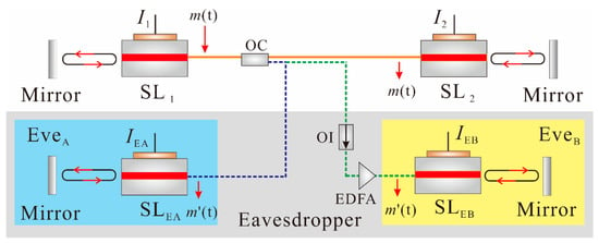
Figure 1.
Schematic diagram of two kinds of eavesdroppers: EveA acted a disguiser that was bidirectionally coupled to the transmitter, and EveB tapped and unidirectionally injected the transmitted light to its laser. SL—semiconductor laser; OC—optical coupler; OI—optical isolator; EDFA—erbium-doped optical fiber amplifier; I—bias current. SL1 and SL2 are lasers of legal users.
The ECLs were modeled by the following Lang–Kobayashi equations [19].
where E(t) is the complex amplitude of optical field and N(t) represents the corresponding carrier density. The subscripts ‘1′, ‘A’, and ‘B’, represent the legal user, EveA, and EveB, respectively. I is the bias current. k is the amplitude feedback strength. τ = 5 ns is the feedback delay time. Ith = 12 mA is the laser threshold current. kA,B = 0.447 is the amplitude coupling strength. Note that, we set kA = 0 in the EveB simulation. τc = 19 ns represents the coupling delay time. Δω = ω1 − ωA,B = 0 denote the detuning angular frequency of the legal user’s laser and the eavesdropper’s laser. The other intrinsic parameters are listed as follows—transparency carrier density N0 = 0.5 × 105 μm−3, differential gain g = 2.125 × 10⁻³ μm3ns−1, gain saturation parameter ε = 1 × 10⁻⁵ μm3, carrier lifetime τN = 2.2 ns, photon lifetime τp = 1.6 ps, linewidth enhancement factor α = 6.0, round-trip time in laser cavity τin = 7.3 ps, active layer volume V = 100 μm3, and the elementary charge q = 1.602 × 10⁻¹⁹ C. The fourth-order Runge–Kutta method, with a step of 2.5 ps was used to solve these equations in the simulation.
The relaxation frequency of the solitary laser without external feedback could be calculated according to the following formula [20]
For a bias current I = 1.6Ith, the used laser had a relaxation frequency of 2.35 GHz.
3. Results
3.1. Principles of the Cracking Process
When moderate optical feedback was applied, the laser generated chaotic oscillation. Figure 2a plots the RF spectrum of laser intensity chaos, which was obtained with a fixed bias current I1 = 1.6Ith and an amplitude feedback strength k1 = 0.08. The spectrum obviously had a dominant peak around the relaxation frequency. This meant that the chaotic carrier had a signature of laser relaxation oscillation. More interestingly, the relaxation oscillation frequency or period could be clearly extracted from the autocorrelation function (ACF) of the temporal waveform which was the inverse Fourier transform of the power spectrum. As shown in Figure 2b, the ACF trace had a side peak closest to the main peak. The location of this side peak was 0.367 ns, corresponding to a frequency of 2.72 GHz, which was the relaxation frequency of the laser with feedback. Note that the slight increase of the relaxation frequency was caused by the optical feedback [20]. Therefore, the signature of relaxation oscillation was quantitatively characterized by the side peak of ACF—the location read the relaxation oscillation period (τRO) and the height indicated the visibility of the ROS.
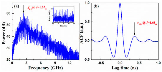
Figure 2.
(a) Power spectrum and (b) the autocorrelation function (ACF) trace of the external-cavity semiconductor laser (ECL) output with a bias current I1 = 1.6Ith and an amplitude feedback strength of 0.08. Arrows denote the fRO and τRO, respectively. The inset plots the temporary waveform of the ECL output.
Figure 3 plots the signature of relaxation oscillation, as a function of the bias current, which was separately obtained at different feedback strengths k1 = 0.08 (circles), 0.1 (triangles), and 0.12 (squares). Figure 3a plots the location of the ACF side peak and also plots the solitary laser’s relaxation period, in black line, which was calculated from Equation (4). Compared to the solitary laser, the external feedback light reduced the relaxation period. The stronger was the amplitude feedback strength, the greater was the decrease of τRO. However, the reduction was quite small. Figure 3b depicts the height of relaxation oscillation as a function of the bias current. The greater the bias current or lower the amplitude feedback strength, the more pronounced were the observed relaxation oscillation characteristics. This indicated that one could easily identify the ROS from the ACF of laser intensity chaos.
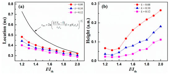
Figure 3.
Relaxation oscillation signature (ROS) as a function of the bias current of ECL: (a) location τRO and (b) height of the ACF side peak. The black curve in (a) the plots τRO of the solitary laser calculated from the formula of the relaxation period.
According to the rule of the aforementioned relaxation oscillation characteristics, the cracking process was implemented with the following formulas (Equations (4)–(6)). It consisted of three main stages: (1) extracting the relaxation oscillation period τRO; (2) calculating the initial bias current IE0, and (3) decreasing IE from IE0. First, τRO was obtained from the power spectrum or the autocorrelation curve of the transmitter chaos carrier, by an eavesdropper; Figure 2. With this τRO, the initial bias current of eavesdropper (IE0) could be calculated using Equation (4)—the formula for relaxation oscillation in the solitary laser without external feedback. Based on the principle of relaxation oscillation in Figure 3a, the bias current of the eavesdroppers was gradually reduced from IE0, until the chaos was synchronized and then the hidden message was deciphered. The advantages of this method were as follows: IE0 could be obtained immediately from the relaxation oscillation period, which narrowed the range of the crack space. On the other hand, the optical feedback light reduced the relaxation oscillation period in the chaotic laser, which indicated the crack direction. As a result, the eavesdropper could crack the secret keys faster than the brute-force attack, using our proposed method.
where P(t) is the intensity time-series of chaotic laser and FT{} denotes Fourier transform.
3.2. Cracking Results
In the simulation, chaos masking was adopted to encrypt the message (binary pseudorandom sequences), for its simple structure. The electrical message was applied on an electro-optical modulator, to modulate a continuous-wave semiconductor laser, with a data rate of 2.5 Gb/s, of which the wavelength and polarization was identical to the transmitter laser, and then the generated optical message was masked into the optical chaos carrier, through an optical coupler. The external modulation index was 0.05. Furthermore, the decoded messages were obtained by a fourth-order low-pass Butterworth filter. We estimated the bit error rate (BER) of the deciphered data, by calculating the Q factor of the eye diagram. The BER threshold of 1.8 × 10⁻³ was used to evaluate the quality of the chaotic communication [21]. That is, the message could be decoded when BER was lower than the BER threshold. Here, we set the bias current of the transmitter as I1 = 1.6Ith. The eavesdropper extracted the τRO of 0.367 ns from the chaos carrier, and the IE0 was considered to be 1.8Ith, according to Equation (4).
Figure 4 gives the eavesdropping results, including the chaotic temporal waveforms and the corresponding eye diagrams of the outputs of SL1 and Eve, with different bias current IE = 1.8Ith and 1.616Ith. For the eavesdropper EveA, when the IEA declined to 1.616Ith, the chaos synchronization was established because of the matched bias current between the SL1 and SLEA. As a result, the opened eye diagram and the BER of 3.12 × 10⁻⁵ meant that EveA had already decoded the message under this scenario, shown in Figure 4(a1,a2). It is worth nothing that the cracking could be achieved by only reducing the bias current of 2.2 mA, with several attempts by EveA.
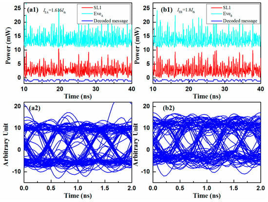
Figure 4.
Examples of eavesdropping with an initial cracked bias current of 1.8Ith. (a1) Temporal waveform of synchronized chaos (red and light blue) and (a2) the decoded signal (blue) of EveA with IEA = 1.616Ith; (b1) temporal waveform of synchronized chaos (red and light blue) and (b2) the decoded message (blue) of EveB with IEB = 1.8Ith. The red line is the transmitted chaos carrier with the encoded message.
For the eavesdropper EveB, as shown in Figure 4b, the message was decoded with a BER of 1.875 × 10⁻⁵ and the system was cracked by utilizing the bias current of IEB = 1.8Ith. The reason was that EveB achieved a high-quality chaos synchronization with SL1, through a unidirectional injection. Compared with EveA, EveB directly cracked the system, with a bias current of 1.8Ith. The results also proved that the security of bidirectionally-coupled synchronization was higher than the unidirectionally-coupled synchronization, in the optical chaos communication [22].
To better qualify the bias current crack range of this communication system, a more careful analysis has been carried out in Figure 5. Figure 5a shows the BER as a function of the bias current mismatches (ΔI = IE − I1). BER threshold is marked with red dash line. It is obvious that cracked ΔI values ranged from −0.25 to 0.25. Additionally, as the IE decreased, the BER gradually decreased to a minimum, and then rose to an unchanged value. The point where BER reached a minimum meant that the IEA was the closest value to I1. Thus, EveA broke this communication system without knowing the bias current and the cracked area resembled the shape of the letter ‘V’, with the bias current mismatches.
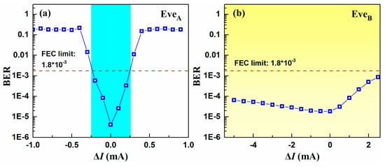
Figure 5.
BER as a function of ΔI between the transmitter and the eavesdropper: (a) EveA and (b) EveB. The blue and yellow shaded areas denote the cracked areas.
As shown in Figure 5b, the BER of SL1 and EveB was always over the BER threshold, which indicated a better eavesdropping, compared with EveA. Unlike the bidirectionally-coupled synchronization in the EveA, a small mismatch induced a dramatic loss, and the unidirectional injection synchronization in EveB scheme showed a better robustness. Unfortunately, this robustness increased the possibility of the optical chaos communication system being cracked [22].
4. Discussion
In our system, the bias current of eavesdropper was determined by the τRO of temporal waveform. However, as can be seen from Figure 3a, with an increasing bias current, the cracked bias current was closer to the real value, which meant that the larger the bias current, the more dangerous the secure optical chaos communication becomes. In addition, a transmitter using the bias current of the ECL as a key, was proposed in the mutually-coupled laser system in our scheme, and the τRO was extracted from the chaos carrier. Thereafter, the bias current was an unsafe key in the optical chaos communication. However, τRO could be eliminated in some chaos generation methods, such as delayed self-interference [23], optical heterodyning of two ECLs [24], and short-cavity VCSEL [25]. In these methods, it was suitable to use the bias current as a key, because an eavesdropper could not achieve the τRO from the chaotic waveform. Hence, eliminating the ROS of ECL could be the direction for future development.
5. Conclusions
In summary, we have analyzed the security of the bias current used as a key in secure optical chaos communication. The τRO and bias current of ECL have been studied in detail. With an increase in bias current, the τRO of ECL always approaches that of a solitary laser. Due to this relationship, two eavesdropping scenarios have been proposed and the results have demonstrated that the bias current used as a key was unsafe in the chaos secure communication, based on the synchronization with the mutually coupled chaotic laser. Results showed that, without the knowledge of the bias current, the eavesdropper could intercept the data from the legal user.
Author Contributions
Conceptualization, D.W., Y.W., and A.W.; Methodology, D.W. and L.W.; Software, P.L., T.Z.; Validation, T.Z.; Formal analysis, L.W. and P.L.; Investigation, D.W.; Resources, Y.W.; Writing—original draft preparation, D.W.; Writing—review and editing, D.W., P.L., Z.J., Z.G., Y.G., and A.W.; Visualization, L.W. and A.W.; Supervision, Y.W.; Funding acquisition, A.W. and Y.W.
Funding
This research was funded by the National Natural Science Foundation of China under grants 61822509, 61671316, 61731014, and 61475111, the National Cryptography Development Foundation under Grant MMJJ20170207, the Program for the Innovative Talents of Higher Learning Institutions of Shanxi, the International Science and Technology Cooperation Program of Shanxi under grant 201603D421008.
Conflicts of Interest
The authors declare no conflict of interest.
References
- Argyris, A.; Syvridis, D.; Larger, L.; Annovazzi-Lodi, V.; Colet, P.; Fischer, I.; García-Ojalvo, J.; Mirasso, C.R.; Pesquera, L.; Shore, K.A. Chaos-based communications at high bit rates using commercial fibre-optic links. Nature 2005, 438, 343–346. [Google Scholar] [CrossRef] [PubMed]
- Argyris, A.; Hamacher, M.; Chlouverakis, K.E.; Bogris, A.; Syvridis, D. Photonic integrated device for chaos applications in communications. Phys. Rev. Lett. 2008, 100, 194101. [Google Scholar] [CrossRef] [PubMed]
- Argyris, A.; Grivas, E.; Hamacher, M.; Bogris, A.; Syvridis, D. Chaos-on-a-chip secures data transmission in optical fiber links. Opt. Express 2010, 18, 5188–5198. [Google Scholar] [CrossRef] [PubMed]
- Sunada, S.; Harayama, T.; Arai, K.; Yoshimura, K.; Davis, P.; Tsuzuki, K.; Uchida, A. Chaos laser chips with delayed optical feedback using a passive ring waveguide. Opt. Express 2011, 19, 5713–5724. [Google Scholar] [CrossRef] [PubMed]
- Tronciu, V.Z.; Mirasso, C.R.; Colet, P.; Hamacher, M.; Benedetti, M.; Vercesi, V.; Annovazzi-Lodi, V. Chaos Generation and Synchronization Using an Integrated Source with an Air Gap. IEEE J. Quantum Electron. 2010, 46, 1840–1846. [Google Scholar] [CrossRef]
- Murakami, A.; Ohtsubo, J. Synchronization of feedback-induced chaos in semiconductor lasers by optical injection. Phys. Rev. A 2002, 65, 184. [Google Scholar] [CrossRef]
- Ohtsubo, J. Chaos synchronization and chaotic signal masking in semiconductor lasers with optical feedback. IEEE J. Quantum Electron. 2002, 38, 1141–1154. [Google Scholar] [CrossRef]
- Chen, H.F.; Liu, J.M. Open-loop chaotic synchronization of injection-locked semiconductor lasers with gigahertz range modulation. IEEE J. Quantum Electron. 2000, 36, 27–34. [Google Scholar] [CrossRef]
- Alvarez, G.; Li, S. Some Basic Cryptographic Requirements for Chaos-Based Cryptosystems. Int. J. Bifurcat. Chaos 2006, 16, 2129–2151. [Google Scholar] [CrossRef]
- Paul, J.; Sivaprakasam, S.; Spencer, P.S.; Shore, K.A. Optically modulated chaotic communication scheme with external-cavity length as a key to security. J. Opt. Soc. Am. B 2003, 20, 497–503. [Google Scholar] [CrossRef]
- Zhao, Q.; Wang, Y.; Wang, A. Eavesdropping in chaotic optical communication using the feedback length of an external-cavity laser as a key. Appl. Opt. 2009, 48, 3515–3520. [Google Scholar] [CrossRef] [PubMed]
- Rontani, D.; Locquet, A.; Sciamanna, M.; Citrin, D.S.; Ortin, S. Time-Delay Identification in a Chaotic Semiconductor Laser with Optical Feedback: A Dynamical Point of View. IEEE J. Quantum Electron. 2009, 45, 879–891. [Google Scholar] [CrossRef]
- Wu, J.; Xia, G.; Wu, Z. Suppression of time delay signatures of chaotic output in a semiconductor laser with double optical feedback. Opt. Express 2009, 17, 20124–20133. [Google Scholar] [CrossRef] [PubMed]
- Oliver, N.; Soriano, M.C.; Sukow, D.W.; Fischer, I. Dynamics of a semiconductor laser with polarization-rotated feedback and its utilization for random bit generation. Opt. Lett. 2011, 36, 4632–4634. [Google Scholar] [CrossRef] [PubMed]
- Li, S.; Chan, S. Chaotic time-delay signature suppression in a semiconductor laser with frequency-detuned grating feedback. IEEE J. Sel. Top. Quantum. 2015, 21, 541–552. [Google Scholar]
- Wang, D.; Wang, L.; Zhao, T.; Gao, H.; Wang, Y.; Chen, X.; Wang, A. Time delay signature elimination of chaos in a semiconductor laser by dispersive feedback from a chirped FBG. Opt. Express 2017, 25, 10911–10924. [Google Scholar] [CrossRef] [PubMed]
- Xu, Y.; Zhang, M.; Zhang, L.; Lu, P.; Mihailov, S.; Bao, X. Time-delay signature suppression in a chaotic semiconductor laser by fiber random grating induced random distributed feedback. Opt. Lett. 2017, 42, 4107–4110. [Google Scholar] [CrossRef]
- Jiang, N.; Wang, C.; Xue, C.; Li, G.; Lin, S.; Qiu, K. Generation of flat wideband chaos with suppressed time delay signature by using optical time lens. Opt. Express 2017, 25, 14359–14367. [Google Scholar] [CrossRef] [PubMed]
- Lang, R.; Kobayashi, K. External optical feedback effects on semiconductor injection laser properties. IEEE J. Quantum Electron. 1980, 16, 347–355. [Google Scholar] [CrossRef]
- Uchida, A. Optical Communication with Chaotic Lasers: Applications of Nonlinear Dynamics and Synchronization; Wiley-VCH: Hoboken, NJ, USA, 2012; pp. 165–166. [Google Scholar]
- Argyris, A.; Grivas, E.; Bogris, A.; Syvridis, D. Transmission Effects in Wavelength Division Multiplexed Chaotic Optical Communication Systems. J. Lightwave Technol. 2010, 28, 3107–3114. [Google Scholar] [CrossRef]
- Klein, E.; Gross, N.; Kopelowitz, E.; Rosenbluh, M.; Khaykovich, L.; Kinzel, W.; Kanter, I. Public-channel cryptography based on mutual chaos pass filters. Phys. Rev. E 2006, 74, 46201. [Google Scholar] [CrossRef] [PubMed]
- Wang, A.; Yang, Y.; Wang, B.; Zhang, B.; Li, L.; Wang, Y. Generation of wideband chaos with suppressed time-delay signature by delayed self-interference. Opt. Express 2013, 21, 8701–8710. [Google Scholar] [CrossRef] [PubMed]
- Wang, A.; Wang, B.; Li, L.; Wang, Y.; Shore, K.A. Optical Heterodyne Generation of High-Dimensional and Broadband White Chaos. IEEE J. Sel. Top. Quantum. 2015, 21, 531–540. [Google Scholar] [CrossRef]
- Muller, M.; Hofmann, W.; Bohm, G.; Amann, M.C. Short-Cavity Long-Wavelength VCSELs with Modulation Bandwidths in Excess of 15 GHz. IEEE Photon. Technol. Lett. 2009, 21, 1615–1617. [Google Scholar] [CrossRef]
© 2019 by the authors. Licensee MDPI, Basel, Switzerland. This article is an open access article distributed under the terms and conditions of the Creative Commons Attribution (CC BY) license (http://creativecommons.org/licenses/by/4.0/).