1. Introduction
In optical backbones, optical packet switching (OPS) has been widely applied due to its reduced overhead and simplified structure of network layers [
1,
2,
3]. With the growing demand for internet protocol (IP) traffic, service providers not only transmit packets through a point-to-point link but also assign to a wide range of network users. OPS, providing a variety services to edge users as well as allowing users to randomly access to the other members, has been seen as a practical solution to metro-area networks (MANs) and local-area networks (LANs). Moreover, to transport data as correctly as possible, error correcting scheme of channel coding is potential for being implemented in these networks. Such coding techniques, including inserting parity bits [
4] and employing iterative decoding to recover bit-interleaved signals [
5,
6], promote the network quality to meet the demanded peak-to-average power ratios and acceptable information loss under given physical constraints. However, optical buffering acts a limitation in OPS, which comes from the immaturity of converting the electrical memory scheme of random access memory (RAM) into the optical domain. This drawback can be partially circumvented by employing optical burst switching (OBS) [
7] supporting bufferless networks or using fiber delay lines (FDLs) as memory units [
8].
The packet switching proposal in OPS, where labels are processed in the optical domain, enables service providers to manage the packet flows more efficiently. As most of the key functions are optically executed, the bottleneck of requiring optical-to-electrical and electrical-to-optical conversions can be alleviated. The conversions performed by the electronic components in routers limit the switching speed and consume considerable power. Therefore, employing OPS to achieve high-quality networks has become a trend in optical communications. OPS maps packet labels into physical layer features such as the time or wavelength of optical signals or optical codes. Core routers recognize the labels to enable a packet to travel along an established link between the edge routers. The link normally includes multiple label switched paths (LSPs). The LSP information represented as optical labels is assigned to a packet before it enters the network.
To identify the overlapping labels in the same optical bandwidth, a multiplexing technique is required at core routers. Optical code-division multiple access (OCDMA), providing high speed and security communications in access networks, has the potential to support all-optical processing [
9,
10,
11]. The obtained label numbers in OCDMA are more flexible than the ones in wavelength-division multiplexing (WDM), and recent literature has demonstrated that OCDMA is compatible with the labeling scheme in OPS [
9,
10,
11,
12]. Converting packet labels into optical codes can be categorized into two methods, the explicit and implicit labels, according to the packet structure [
12]. For explicit labels, edge routers attach the encoded optical signals to a packet’s head. If the core routers fail to recognize the labels correctly, it results in great degradation as the entire packet drops. For implicit labels, each payload bit in a packet is programmed into an OCDMA signal. It reaches a high transmission efficiency as the implicit labels and the payload are located in the same time slots or bandwidth. The incorrectly decoded labels in a specific payload bit can be compensated by the correctly decoded labels carried by other bits in the same packet, and the lost payload bit is reduced. Therefore, the author preferred to employ implicit labels to better fit the labeling mechanisms in OPS.
With the increased stability of fiber channels and the emergence of multimedia services over the Internet, network users expect service providers to support communications with different classes of quality-of-service (QoS). In typical optical communication systems, multi-service transmissions mainly focus on differentiated bit-error probabilities (BEPs) [
13,
14]. BEP values can be varied by performing digital signal processing (DSP) at the decoder [
13] or modifying the optical signals [
14]. In current OPS, except for BEP, different demands of signaling rates are required to exist together in the same network.
In this paper, the author introduced a multi-rate switching strategy in generalized multi-protocol label switching (GMPLS) by employing the multiple-code (MC) technique [
15]. In the proposed scheme, the signal rate of packet flow is varied with the number of OCDMA labels carried by a packet. Spectral-amplitude-coding (SAC), which represents the chips in an OCDMA code as a set of wavelengths, was introduced to remove the multiple-access interference (MAI) from the overlapping among labels. The proposed architecture was capable of providing arbitrary classes of bit-rates rather than a simple two-class scenario. The label assignments to core routers and the packet structure were demonstrated in detail. Furthermore, except for the bit-error probability (BEP), the author derived the network spectral efficiency (SE) to describe the network characteristics more adequately.
The rest of this paper is structured as follows. In
Section 2, typical multi-rate schemes in OCDMA systems are reviewed. In
Section 3, the author covers concepts of multi-rate switching in OPS and demonstrates the packet structure in time and wavelength domain. Hardware implementations of generating and detecting OCDMA labels in multi-rate transmissions are discussed in
Section 4.
Section 5 focuses on the performance analysis of network BEP and SE. The last section brings a conclusion.
2. Related Works
Several schemes of providing multi-rate transmissions in OCDMA have been proposed [
15,
16,
17]. In [
16], users sent data bits as multi-length variable weight (MLVW) sequences based on their requested services. Multi-rate service is achieved by selecting codes with various lengths and weights, where the high-weight and low-length codes are employed for the packets with a higher bit rate. Another multi-rate OCDMA scheme is known as multi-code keying (MCK) [
17]. Instead of the one-on-one mapping of a data bit to a code sequence, several bits are included in a code symbol in MCK where the data rates can be switched by assigning different bit numbers to a symbol. The concept of MC is to express a serial bit stream into
M parallel branches. Each parallel bit is encoded with a specific OCDMA code. Then,
M codes are multiplexed in a shared channel and transmitted simultaneously. Receivers recover the bit sequence by serial-to-parallel conversion after the multiplexed signals are decoded. Users are able to transmit data with
M times of the basic bit rate by setting different numbers of parallel branches and codes.
Compared with the previously mentioned multi-rate schemes MLVW and MCK, MC has several advantages. First, the encoder/decoder structure for generating/recognizing OCDMA labels can be unified, while several codec designations are required for supporting MLVW labels with various code lengths and code weights. Furthermore, MC outperforms MCK in network flexibility. The gains of bit-rate in MC can be scaled to any arbitrary positive integers M, while the gains in MCK are limited to discrete values of 2M. The code utilization in MC is also more efficient. To achieve M times of the basic bit rate, up to 2M codes are required to express a symbol of M bits in MCK, while only M codes are sufficient to transmit M bits in the basic duration for MC.
However, when multiple codes are used for high-rate transmissions, multiple-access interference (MAI) is accumulated from the overlapping label signals. Detection errors will increase significantly if the MAI is over an acceptable threshold at the decoder. Therefore, the author adopted spectral-amplitude-coding (SAC) [
18,
19,
20] to eliminate the MAI effect. Combining the characteristics of SAC codes and an interference cancellation algorithm known as balanced detection, MAI can be blocked at the receiver. In the existing research, the investigations in the multi-rate code-switched network have been limited to phase-coding and time-spreading OCDMA. Therefore, the contribution of this paper is to analyze the performance of multi-rate switching based on SAC labels.
4. Hardware Design of Codec for Multi-Rate Labels
Figure 6 shows the architecture of packet generation for the proposed multi-rate network. For payload bits of class
m, the serial bit stream is divided into
m parallel streams. Here, it is assumed that the network supports up to
M different signal rates and 1 ≤
m ≤
M. An encoder array optically labels each bit in the parallel branch with a set of optical codes. The code set consists of
pm labels, where
pm is the LSP number in the end-to-end path for the packet of class
m. Here, a label is denoted as C(
x,
y,
z), where
x is the user class,
y is the parallel branch number, and
z is the number of LSPs, respectively. For label generation, each packet is sent to a given number of encoder arrays according to its class of signal rate. The labels of the lowest rate packets are formed by a single encoder array. The high-rate packets with
m times of the lowest rate are formed by
m encoder arrays. After labeling, packets of various classes are aggregated and forwarded to the network.
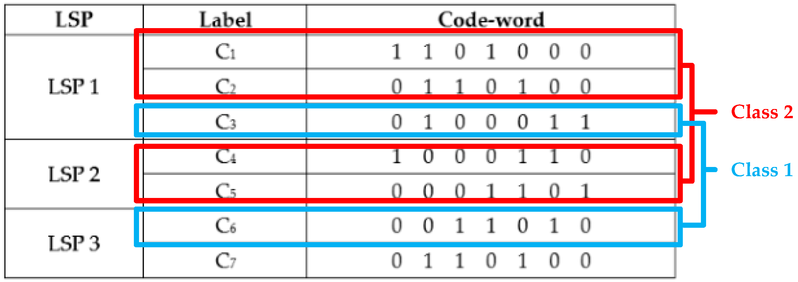
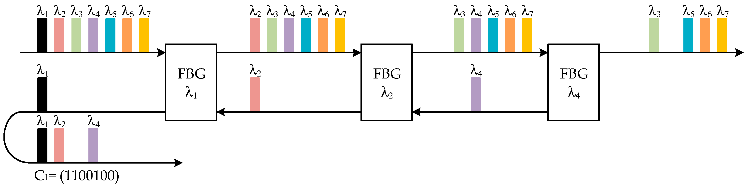
Figure 7 shows a BIBD encoder for creating a SAC label. An encoder array of class
m in
Figure 5 contains
Pm encoders that generate
Pm labels for a payload bit. Each encoder is made up of
w fiber Bragg gratings (FBGs) and an optical combiner. A light source with a bandwidth of
L wavelengths is sent to FBGs of central wavelengths λ
i, where
i is the position of the chip “1s” in a BIBD code vector. For example, the values of
i for C
1 = (1 1 0 1 0 0 0) are 1, 2, and 4. When the optical pulses of the light source enter a FBG, the wavelength component matching the central wavelength is reflected. The wavelength components reflected from three FBGs, λ
1, λ
2, and λ
4, represent the SAC label encoded on the optical spectrum. The unused wavelengths corresponding to chip “0s” are not collected by the encoder as they pass through the FBGs.
Implementing multi-rate transmission with multi-code labels requires the deployment of OCDMA decoders in the router architecture. The key function of label processing is to realize the optical codes carried by packets of various data rates.
Figure 8 shows the architecture of a core router capable of packet switching over the network of multi-rate label assignment. At each core node, the aggregated packet flow is divided and sent to
M decoder arrays for label decoding. While the label identification is processed, the packet stays in the optical domain. When a packet is switched at a core router, the fiber delay line (FDL) in
Figure 8 can be seen as a replacement of an optical buffer. The queue of packet achieving by the FDL is required to compensate the label processing time. Provided with the decoded result, an optical cross-connect (OXC) switches the packet to the destined LSP based on the label information in the stack. The decoder structure for identifying a BIBD label is similar to that of the encoder, as shown in
Figure 9. The primary purpose is to calculate the correlation value of the wavelength train of the label stack with the wavelength-domain function of cascade FBGs. The implementation of FBGs is in the reversed order to compensate for the traveling time of wavelengths in the encoder. An additional attenuator of 1/(
w − 1) is attached so that the decoder operation is the same as Equation (3). The balanced detector ensures that the MAI of the unrelated labels is blocked. The original payload bit is restored from the wavelength signals to the data pulse in the time-domain.
5. Performance Analysis and Discussion
In this section, the author considers the variations of the decoded signal at the core routers due to the phase-induced intensity noise (PIIN) and thermal noise in the optical-electrical conversion of the balanced detector. As all packets of different classes were generated by a standard light source, it was assumed that each label reaching the decoder at core routers had equivalent power. In the following analysis, the author employed an unpolarized light source with the flat power spectral density (PSD) of
Psr/∆
v over ∆
v. Here,
Psr denotes the effective power received by the decoder in dBm and ∆
v is the light source bandwidth in Hz. At the output of a specific decoder, the average photo-current of a decoded BIBD label when the payload bit is “1” is expressed as:
where
R is the responsivity of the photo-diodes in the balanced detector. Given the condition that
K labels simultaneously enter the decoder, the average PIIN power is [
21]:
where
B is the electrical bandwidth. The total label number
K is defined as
when the user sends payload bits “1” and “0” with equal probability in a packet. The BEP for the payload bit encoded with a single label can be obtained by employing the following equation:
where
is the variance of the thermal noise. For the packets of class
m, as
m labels are multiplexed in a basic time duration
Tb, the BEP for the packets is expressed as BEP
m = 1 − (1 − BEP
m).
Figure 10 shows the relationship between BEP and the class of user bit-rates. Parameters used for the simulations were
R = 0.85 A/W,
Psr = −10 dBm,
B = 100 MHz, and ∆
v = 3.75 THz, respectively. For packets of class
m, the bit-rate was set at
mRb, where
Rb was the lowest bit-rate of class 1 and
Rb = 155 Mb/s. Here, five classes of packets using BIBD codes of
w = 9 and
L = 73 as labels were simultaneously transmitted and decoded at the core routers. It was assumed that the switching paths for all classes of packets had the same LSP number,
p1 =
p2 = … =
p. For a given LSP number
p, the BEPs of the five classes are nearly constant, and the variations of performance among classes can be neglected. The result revealed that the proposed scheme provides an OPS network with a stable function of switching multi-rate packets. Moreover, LSP numbers of 2, 3, and 4 were demonstrated in this figure for comparison. The case of
p = 2 reached the smallest BEPs, as a packet carries fewer labels to travel the link with a small LSP number.
The relationship between BEP and the LSP number p for different user distributions is shown in
Figure 11. The author analyzed three cases of a two-user scenario, where the differences among the cases were the user numbers in class 1 and 2. Given a fixed user number (
K = 2), the BEPs of class 2 (
K2 = 2) were higher than those of class 1 (
K1 = 2), where K
m is the user number in class
m, and
m = 1, 2. The BEPs for the hybrid scheme, where users of both classes coexist (
K1 =
K2 = 1), are in the middle of the pure high-rate and the pure low-rate schemes. As high-rate users require more labels to perform packet switching under the same switching path, they suffer more considerable noise power. Furthermore, since PIIN variance is positively related to the LSP number, the performance becomes worse as
p increases.
Shown in
Figure 12 are the curves of the user class
m versus LSP number
p of three cases of BEPs. Based on the previously mentioned analysis, BEP is determined by the total label number
K. When a single-class scenario is considered,
K is the product of
m and
p, so one parameter is inversely proportional to the other. The figure shows that a packet travels a longer LSP at the expense of the reduced signal rate.
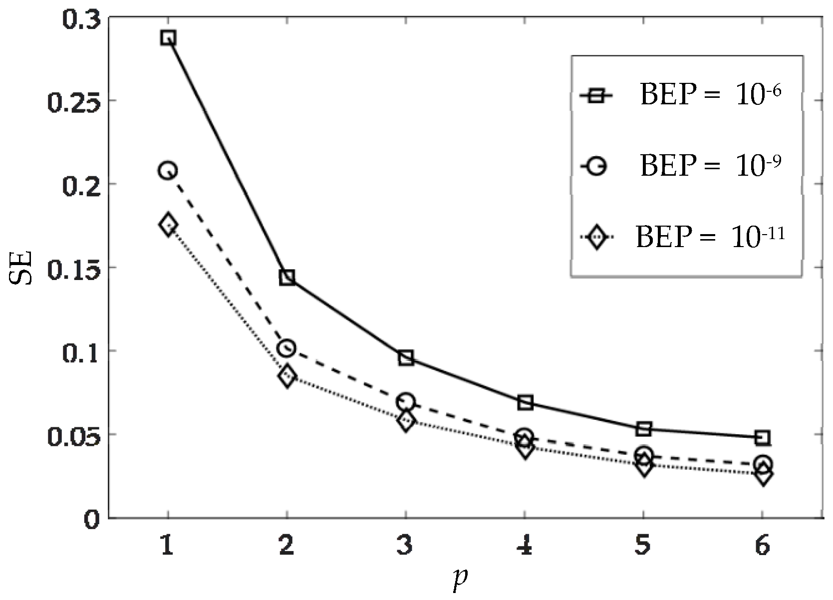
Figure 13 shows the relationship between spectral efficiency (SE) and the LSP number
p, and three cases of BEPs were compared. SE, a performance index to evaluate bit-rates for a given BEP, has the following definition [
22]:
It can be seen in
Figure 13 that SE increased with the required BEP. This is because more users are allowed to transmit data when the network increases the acceptable level of noise power. When the LSP number
p is small, a better SE is yielded at the expense of the reduced switching path. The tradeoff between SE and the distance of packet switching requires careful considerations when the network is designed. Note that SE is independent of class number
m. When a different value
m is assigned, the available user number and the bit-rate become
K/
m and
mRb, respectively. However, the result of SE in Equation (3) remains unchanged as the product of these two parameters is a constant.
6. Conclusions
In this paper, the author investigated a multi-rate OCDMA scheme to meet the requirements of multimedia services in current OPS networks. A packet switching system based on the multi-code technique was proposed where the packets of various bit-rates were combined and transmitted simultaneously. Numerical examples of packet label encoding and decoding were demonstrated to validate the multi-rate models. In addition, the author described the packet structure and the hardware implementation of the routers. Some performance indexes such as the BEP and SE were derived from the mathematical formula modeling the photo-current and the noises of the decoded labels. Based on the simulation results, the network BEP is a constant function of the user class m, which implies that packets of various data rates can be switched with the benefit of stable performance. Moreover, an analysis of the combinations of user numbers among bit-rate classes was conducted. The findings showed that high-rate users were more sensitive to the changes in LSP numbers, as more labels were required to switch the packets along a given link compared with the low-rate ones. A large number of overlapping labels induced a higher noise power at the decoder and BEP was increased. Finally, the SE of the proposed network was analyzed and the tradeoff between SE and the switching path distance was demonstrated.
Designing a hybrid model that integrates two or more multi-rate techniques is an exciting topic. By considering the pros and cons of each scheme, the hybrid network is flexible to meet the various requirements of operating environments. For future works, the author aims to extend the independent MC design in OPS to a collective one. The user assignment to each multi-rate scheme, the structure of optical encoders/decoders, and the multi-rate switching strategies in OPS require further investigations.


