Article

Double-Slot Hybrid Plasmonic Ring Resonator Used for Optical Sensors and Modulators

1
School of Information and Communication Technology, KTH Royal Institute of Technology, 164 40, Kista, Sweden
2
JORCEP, Joint Research Center of Photonics of the Royal Institute of Technology (Sweden) and Zhejiang University (China), Hangzhou, 310058, China
3
Centre for Optical and Electromagnetic research, State Key Laboratory for Modern Optical Instrumentation, Zhejiang University, Zijingang Campus, Hangzhou, 310058, China
4
Department of Theoretical Chemistry and Biology, KTH Royal Institute of Technology, 106 91 Stockholm, Sweden
5
Hewlett-Packard Laboratories, Palo Alto, CA 94304, USA
*
Author to whom correspondence should be addressed.
Photonics 2015, 2(4), 1116-1130; https://doi.org/10.3390/photonics2041116
Submission received: 15 October 2015 / Revised: 11 November 2015 / Accepted: 19 November 2015 / Published: 25 November 2015

Abstract

:
An ultra-high sensitivity double-slot hybrid plasmonic (DSHP) ring resonator, used for optical sensors and modulators, is developed. Due to high index contrast, as well as plasmonic enhancement, a considerable part of the optical energy is concentrated in the narrow slots between Si and plasmonic materials (silver is used in this paper), which leads to high sensitivity to the infiltrating materials. By partial opening of the outer plasmonic circular sheet of the DSHP ring, a conventional side-coupled silicon on insulator (SOI) bus waveguide can be used. Experimental results demonstrate ultra-high sensitivity (687.5 nm/RIU) of the developed DSHP ring resonator, which is about five-times higher than for the conventional Si ring with the same geometry. Further discussions show that a very low detection limit (5.37 × 10⁻⁶ RIU) can be achieved after loaded Q factor modifications. In addition, the plasmonic metal structures offer also the way to process optical and electronic signals along the same hybrid plasmonic circuits with small capacitance (~0.275 fF) and large electric field, which leads to possible applications in compact high-efficiency electro-optic modulators, where no extra electrodes for electronic signals are required.

Graphical Abstract

1. Introduction

The possibilities of miniaturization, mass production, low power consumption and wide bandwidth cause photonic integrated circuits (PICs) [1] to play an increasingly important role in various applications. In particular, for electro-optic (EO) polymer-based optical modulators and refractive index (homogenous) sensors, the waveguide sensitivity to refractive index changes is one of the vital parameters. Many waveguide structures, including dielectric waveguides [2,3,4,5,6,7,8,9,10,11,12], subwavelength grating waveguides [13], hollow core waveguides [14], dielectric slot waveguides [15,16,17,18,19] and plasmonic slot waveguides [20], have been designed and optimized to increase the optical confinement factor of covering or infiltrating materials and, hence, to increase sensitivity. In contrast to dielectric- and subwavelength grating waveguide-based sensors (evanescent optical sensing), slot waveguides or hollow core waveguides can confine optical power in the narrow slots or hollow cores, which leads to large optical sensitivity to materials infiltrating the waveguides. In the following, we have limited our investigations to slot waveguides. The principles of slot-guiding waveguides are different from ordinary index guiding: for a dielectric slot waveguide, the optical confinement is provided by the special high-low-high indices’ structures, where the large index-contrast makes the optical power propagate in the low index slot; for the plasmonic slot waveguide, confinement is achieved by plasmonic optical enhancement, where optical energy is excited and propagated at the surface of metal layers. Generally speaking, plasmonic slot waveguides have better optical confinement than dielectric slot waveguides, due to the ultra-compact size, however, at the expense of larger propagation loss. To combine the advantages of both dielectric and plasmonic slot waveguides, a double-slot hybrid plasmonic (DSHP) waveguide, a novel high optical confinement, low propagation loss waveguide, has been developed [21,22].
The DSHP waveguide structure shows the advantages of low propagation loss, high optical confinement and a fabrication process compatible with conventional silicon on insulator (SOI) technologies. In [22], a DSHP Mach-Zehnder Interferometer (MZI) resonant sensor is experimentally demonstrated. In this paper, we continue our work on the investigation of the DSHP waveguides using here ring resonator structures. In comparison to MZI resonant cavities, the ring resonator has a better quality factor, which will give a smaller detection limit for optical sensor applications and can also decrease the power consumption for electro-optic (EO) modulators.
In this paper, based on detailed simulation investigations, a Si bus waveguide side-coupled DSHP ring is designed, fabricated and characterized, showing the potential of applications in highly-efficient optical homogenous sensors and in EO polymer-based modulators.

2. Double-Slot Hybrid Plasmonic Ring

2.1. Schematic and Simulation Method

As shown in Figure 1a, the DSHP ring resonator consists of a Si ring located between Ag (or other plasmonic material) circular sheets. When the slots between the Ag sheets and Si ring are narrow enough (less than 500 nm), the quasi-transverse electric (TE) hybrid photonics (Si-slot materials) and plasmonic (slot material-Ag) guided mode can be supported. In the ring structure, it is propagating as the known whispering-gallery mode.
Figure 1. (a) Schematic of a double-slot hybrid plasmonic ring resonator; (b) x-z plane cross-section view; (c) power distribution of the x-z plane cross-section simulated by the axisymmetric finite element method. IPA, 2-isopropanol.
Photonics 02 01116 g001
The x-z cross-section view is shown in Figure 1b. SiO2 is used as the buffer layer, and liquids to be tested (or electro-optic polymer) are filling the slots and covering the device (infiltrating the device). The radius of the DSHP ring r is equal to the middle radius of the Si ring, as shown in Figure 1b. The width of the Si ring is denoted by wSi; the heights of the Si and metal layers are identical and denoted by hWG; the widths of the slots are wslot, and w is the total width (w = wSi + 2wslot).
The power distribution of the simulated DSHP ring is shown in Figure 1c using the axisymmetric finite element method (FEM) [23], where the commercial simulation software, COMSOL Multriphysics, is used to solve the partial differential equation in cylindrical coordinates. The geometrical parameters are: hWG = 250 nm, wSi = 300 nm and wslot = 150 nm. The refractive indices of Si and SiO2 are 3.45 and 1.45, respectively, for the operation wavelength of 1550 nm. The infiltrating material is pure 2-isopropanol (IPA), whose refractive index is 1.3739 [24] at 1550 nm.
The properties of Ag are calculated by the Drude model [25]:
ε = ε ω p 2 ω 2 + j ω γ
where ε = 3.1 , ω p = 140 × 10 14 rad/s and γ = 0.31 × 10 14 rad/s .

2.2. Model Investigation

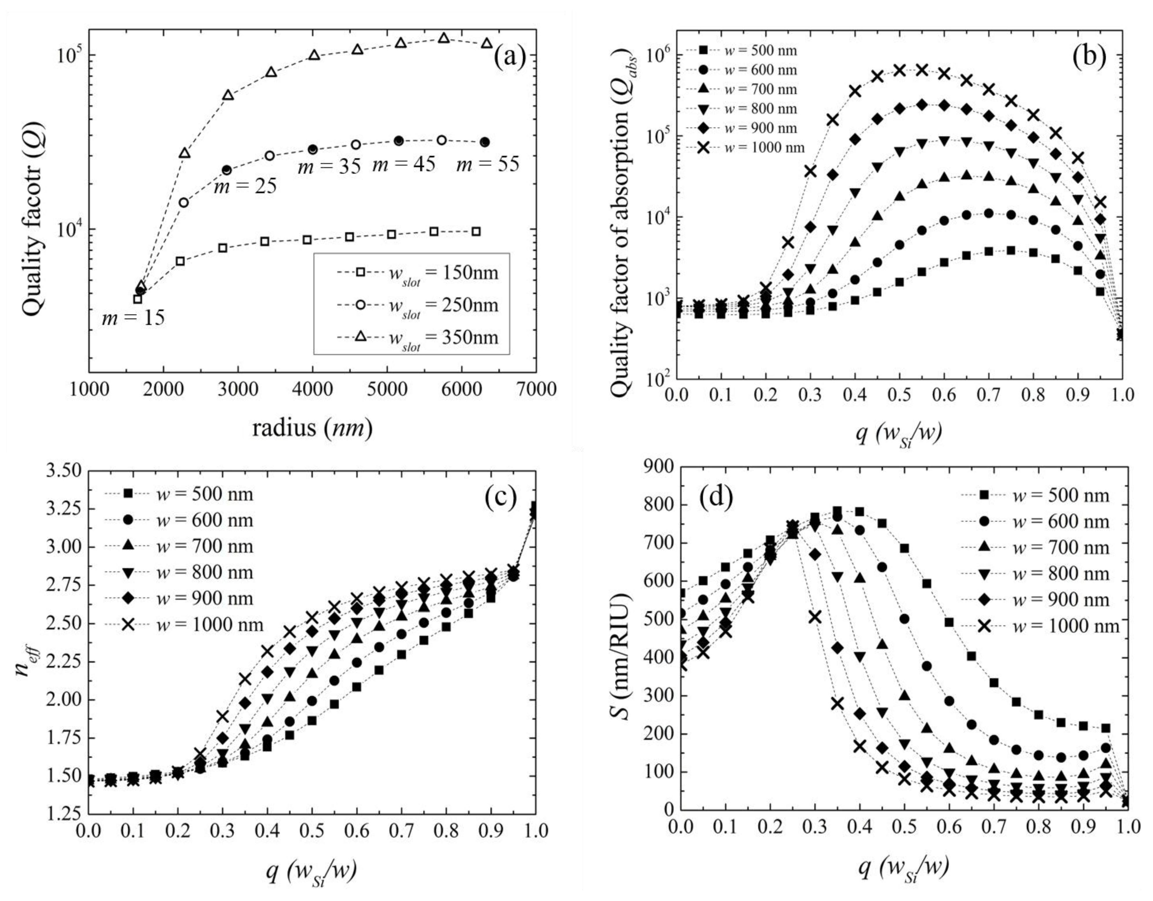
The model investigations start from the generalized analysis of the quality factors (Q factors) of the DSHP ring with various widths of the slots, as shown in Figure 2a. The geometrical parameters of the DSHP ring are: wSi = 350 nm and hWG = 250 nm. In the simulation process, the resonant wavelength is fixed around 1550 nm, and the azimuthal numbers (m) are changed from 15 to 55 with a step of five. The radii of the DSHP ring are adjusted according to the resonant condition of whispering-gallery mode:
2 π r = m λ / n e f f
The Q factor is calculated by:
Q = f e i g ( r e a l ) 2 f e i g ( i m a g )
where feig(real) and feig(imag) are the real and imaginary parts of the eigenvalue of the m-th order whispering-gallery mode, which can be directly readout from the simulation software.
Without considering the coupling loss, the Q factor of the DSHP ring is influenced by absorption and radiation losses [26], which can be written as:
1 Q = 1 Q a b s + 1 Q r a d
Here, Qabs and Qrad are the absorption and radiation quality factors of the ring, respectively.
As shown in the figure, the Q factor increases with the radius due to lower radiation loss; when the radius is large enough (larger than 6 μm), the radiation loss can be ignored, while the initial properties of the DSHP waveguide (absorption loss) play a more significant role in the Q factor, which tends to a constant value for specific geometrical parameters. In addition, the Q factor of the DSHP ring with wider slots is larger, which means that the absorption loss of the DSHP waveguide with wider slots is smaller due to lower plasmonic material influence.
Summarizing the information given above, the absorption loss (or Qabs factor) is the major property of a DSHP ring with a large enough radius. In order to study the Qabs factor of the DSHP ring, one can fix the radius of the DSHP ring at 6 μm (radiation loss can be ignored) and change the geometry of the DSHP waveguide. In this way, the normal FEM simulation method can be used to study the properties of a DSHP waveguide per se. Since the hybrid propagation mode is a mixture between photonic and Surface Plasmon Polariton (SPP) modes, a q-parameter (q = wSi/w), representing the occupancy of a photonic mode, is used to study and optimize the performance of the DSHP ring resonator.
Figure 2b shows the Qabs factor versus the q-parameter, when the total width of the DSHP ring is changed from 500 nm to 1000 nm. The Qabs factor is estimated by:
Q a b s = ω n g c α
where ng is the group index of the confined whispering-gallery mode, which is expressed by:
n g = n e f f ( r e a l ) λ d n e f f ( r e a l ) d λ
neff(real) is the real part of effective refractive index. The dispersion of neff, d n e f f ( r e a l ) / d λ , is computed by re-simulating the DSHP waveguide with a wavelength of λ + Δ λ , and the neff at λ + Δ λ can be obtained, which is denoted as n e f f ( λ + Δ λ ) .
Figure 2. (a) Q factor versus the radius of the double-slot hybrid plasmonic (DSHP) ring resonator with various widths of the slots (150 nm, 250 nm and 350 nm); the other geometrical parameters are: wSi = 350 nm and hWG = 250 nm; (b,c,d) the Qabs factor, effective refractive index and sensitivity changes with the q-parameter for waveguides with a total width w of 500 nm, 600 nm, 700 nm, 800 nm, 900 nm and 1000 nm.
Photonics 02 01116 g002
Then, the dispersion can be estimated by:
d n e f f ( r e a l ) d λ = n e f f ( λ + Δ λ ) n e f f ( λ ) Δ λ
α in Equation (5) is the absorption coefficient, which can be written as:
α = 4 π λ n e f f ( i m a g )
where neff(imag) is the imaginary part of effective refractive index.
After simulating the DSHP waveguide, the Qabs factors versus the q-parameter are calculated according to Equation (5), as shown in Figure 2b, where the total widths of the DSHP waveguide are changed from 500 nm to 1000 nm with a step of 100 nm. One can observe that the Qabs factor of the DSHP ring decreases with a smaller width due to the larger influence of the plasmonic layers in the narrower DSHP waveguide. For the DSHP rings with the same total width, there are optimal values of the q-parameter giving the maximum Qabs factor, which expresses the hybrid propagation modes of the DSHP ring, where the propagation loss is much lower than that of a pure plasmonic slot waveguide (when q is equal to either zero or one).
Values of neff versus the q-parameter for different total widths are shown in Figure 2c. The neff increases with the occupancy of the slot by the Si ring (increase of q), which needs to be explained from two aspects: (1) the high refractive index of Si has greater influence and causes higher neff of the DSHP waveguide; and (2) with the higher q-parameter, wslot of the DSHP ring is small, and so, the optical confinement is larger. The former explanation concerns the photonic mode, and the latter one concerns the plasmonic optical enhancement. The interaction between photonic and plasmonic modes leads to the nonlinear behavior of neff.
In addition to the basic studies of the DSHP ring, we also analyze its sensitivity to infiltrating materials. The sensitivity is given by:
S = λ r e s n cov e r = λ Δ n e f f n g / n cov e r
where ∂λres is the resonant wavelength shift and ∂ncover is the refractive index change of infiltrating materials (∂ncover is set to be 0.003 in the simulation); Δneff is the change of effective indices of the DSHP waveguide infiltrated with different materials.
As shown in Figure 2d, the sensitivity of the narrower waveguide is higher due to the better optical confinement. In addition, optimal q-parameters are also observed for the sensitivities of the DSHP ring, which means that the sensitivity is also enhanced by the hybrid modes compared to pure plasmonic modes (q = 0 or 1). The maximum sensitivity can reach a value as high as 700 nm/RIU when w = 500 nm and q = 0.35, which can be further increased by decreasing the total width, however, at the expense of a lower Qabs factor. The trade-off between the Qabs factor and sensitivity is similar to the one between propagation loss and optical confinement, which is a general behavior in hybrid plasmonic and plasmonic waveguides [21,27]. Based on the different behaviors of the Qabs factor and the sensitivity of the DSHP ring, one needs to carefully design the geometry of the DSHP ring to satisfy the requirements for particular applications.

3. Experimental Realization

3.1. Si Side-Coupled DSHP Ring Resonator Design
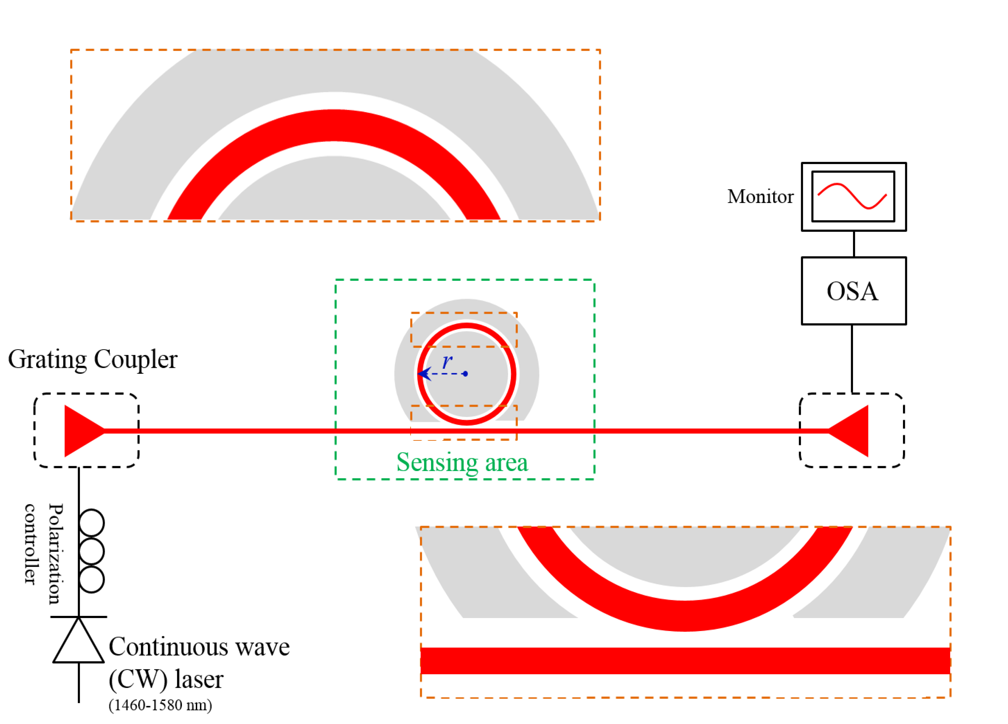
In a conventional SOI technology, a side-coupled Si bus waveguide is commonly used to characterize the performance of ring resonators. However, in our case, due to the presence of the outer Ag ring, almost no optical energy from the bus waveguide would be coupled into the DSHP ring. To solve this problem, one can reconfigure the DSHP ring with a partly open area, as shown in the sub-figure of the coupling area in Figure 3, where a part of the outer Ag ring is taken away. The gap between the Si bus waveguide and the DSHP waveguide is designed to be 100 nm to 200 nm, to find the experimental critical coupling condition. The geometrical parameters of the DSHP ring are: wslot1 = 250 nm, wslot2 = 350 nm, wSi = 350 nm and hWG = 250 nm. Special attention needs to be paid here to the different widths of slots, which is in accordance with the conformal mapping theory of a ring resonator [28]: the power of the outer slot of the whispering-gallery mode is larger than the inner slot, which results in the unbalance between the two slots of the DSHP ring. The unbalance will cause larger propagation loss (or lower Q factor) due to a large part of the light confined at the slot material-Ag interface compared to the DSHP waveguide without bending. In order to compensate such unbalance, the outer slot can be designed to be slightly wider than the inner one. Besides, the wider outer slot will also decrease the neff mismatch between the modes propagating in the open and closed areas of the DSHP ring, hence reducing the propagation loss of the designed, partly open DSHP ring resonator. Grating couplers are applied at each end of the device for the coupling between an optical fiber to on-chip devices.
Figure 3. Schematic of the Si bus waveguide side-coupled double-slot hybrid plasmonic ring sensor. The sub-figures are the detailed structures of the coupling area and the DSHP ring. The measurement setup is also illustrated. OSA, optical spectrum analyzer.
Photonics 02 01116 g003

3.2. Fabrication and Measurement Setup

The fabrication starts from a commercial SOI wafer with 250-nm crystalline Si on top of a 3 μm-thick SiO2 buffer layer. E-beam lithography (EBL) is used to pattern the Si structure. Then, inductively-coupled plasma (ICP) dry etching with 10% over etch is performed, followed by a second EBL and ICP dry etching processes to fabricate the highly-efficient non-uniform grating couplers [29]. Finally, the pattern of the silver pads is introduced by the third E-beam exposure. After patterning, 20-nm Ge and 230-nm Ag layers are evaporated by a metal evaporation tool, where the Ge layer is used to increase the adhesive strength between silver and substrate material (SiO2). Then, a metal lift-off process is used to open the silver structures.
The optical characterization is carried out by the grating coupler setup, as shown in Figure 3: the input/output optical fibers are placed above the grating couplers at each end of the tested device. The tunable continuous wave (CW) laser and polarization controller are connected to the input fiber, while the optical spectrum analyzer (OSA) is connected to the output fiber. The test liquids (100% and 80% concentrations of IPA in water) are directly dropped onto the surface of the tested sample. The transmission response of the tested device is then obtained after adjusting the positions of input and output optical fibers.

3.3. Characterization Results

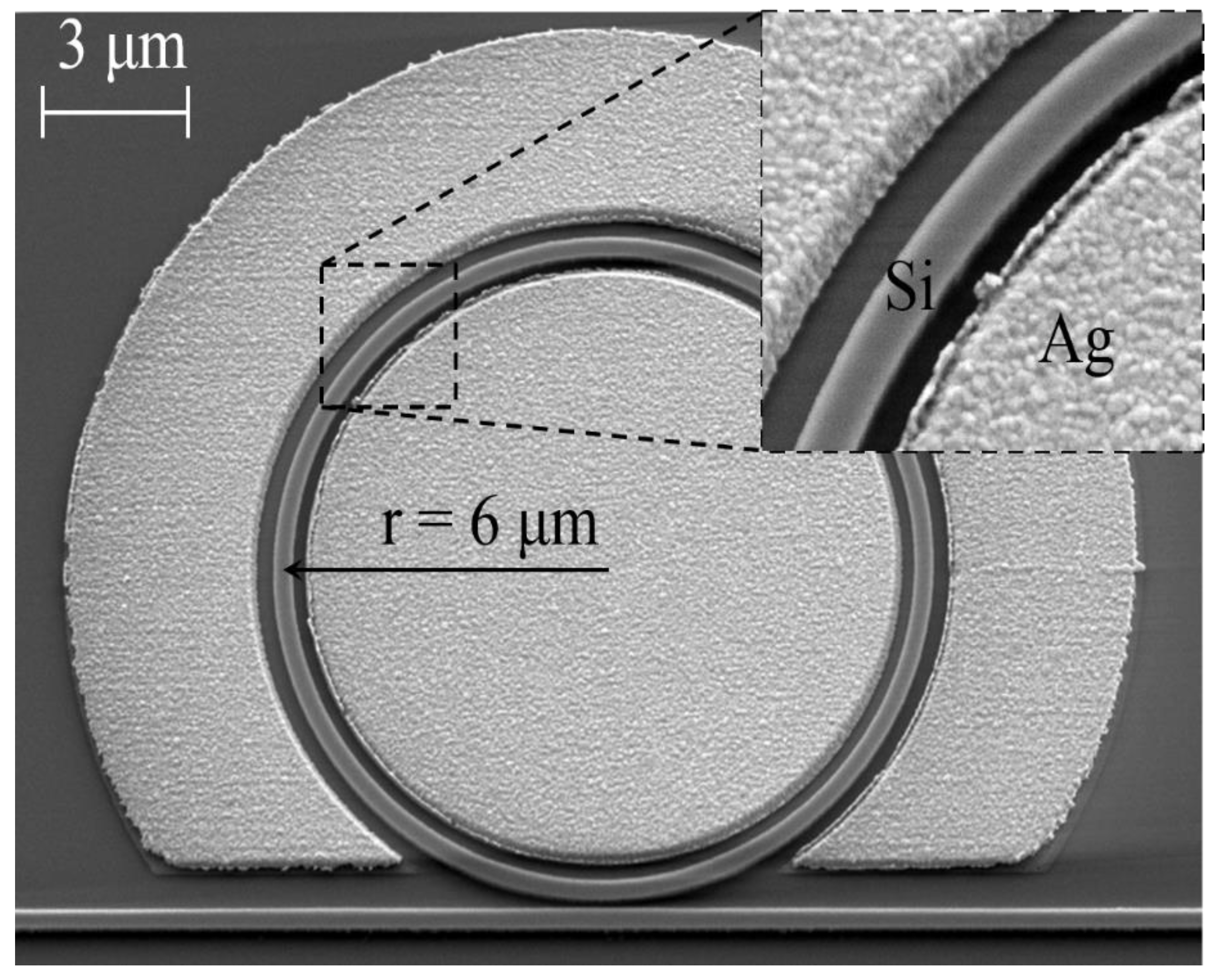
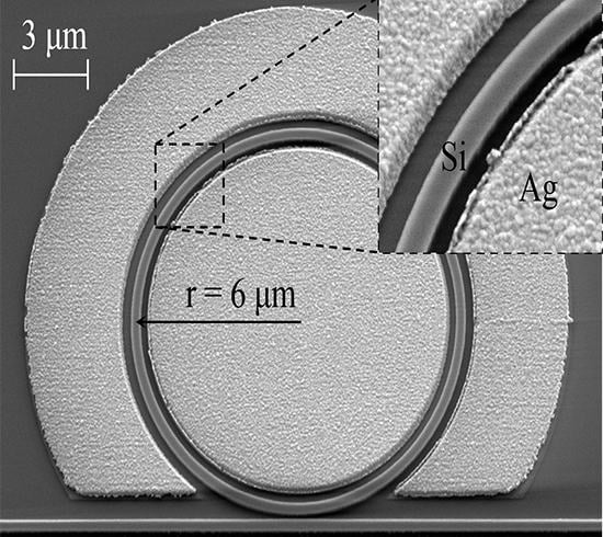
The scanning electron microscope (SEM) view of the fabricated DSHP resonator is shown in Figure 4. The radius of the fabricated DSHP ring is about 6 μm, and the width of the Si ring and bus waveguide is 350 nm. The outer and inner slots have widths around 350 nm and 250 nm, respectively.
Figure 4. Scanning electron microscope picture of the fabricated double-slot hybrid plasmonic ring sensor.
Photonics 02 01116 g004
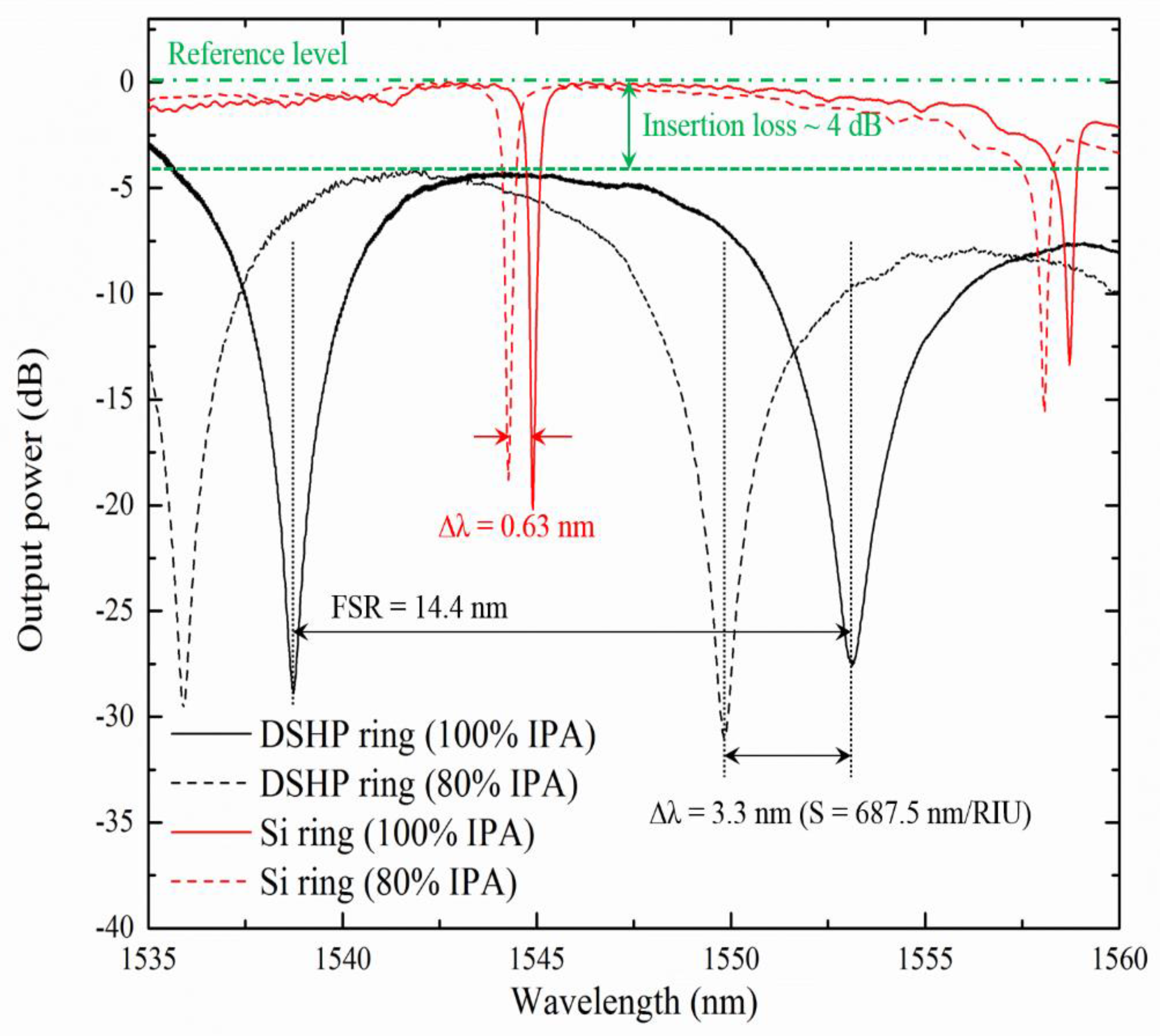
Figure 5 shows the transmission responses of the DSHP ring (black curves) and pure Si ring resonator (red curves) infiltrated with 100% IPA (solid curve) and 80% IPA (dashed curve). The green reference level is the transmission response of a straight Si waveguide with input/output gratings. For the DSHP ring resonator, the insertion loss, excluding grating coupler loss, is around 4 dB. The extinction ratio is larger than −25 dB, and the free-spectral-range (FSR) is about 14 nm. The wavelength shift of the DSHP ring is 3.3 nm, which is about 5-times higher than that of the Si ring (0.63 nm). The refractive index of 80% IPA at a 1550-nm wavelength can be estimated by the reference Si ring transmission responses: according to the simulation results, the Si ring with a 350-nm width has a sensitivity of 132.41 nm/RIU. Calculated from the resonance peak shift (0.63 nm), the refractive index change of the infiltrating material is 0.0048, which gives the refractive index of 80% IPA in water of 1.3691. Based on the data measured with a wavelength of 589 nm in [30], this value is reasonable. The corresponding sensitivity of the fabricated DSHP ring is 687.5 nm/RIU, slightly higher than the simulation result (~600 nm/RIU), which is caused by: (1) the coupling area providing additional sensitivity to the final results; and (2) the fabrication roughness of the Si and Ag elements inducing larger radiation losses compared to the theoretical situation and the radiated optical energy increasing the optical energy located in the infiltrating analytes, hence increasing the sensitivity.
Figure 5. Characterization results of the double-slot hybrid plasmonic ring sensor (black curves) and a silicon ring resonator with the same radius (red curves) infiltrated with 100% and 80% 2-isopropanol. The reference level is the transmission response of the straight waveguide with input/output grating couplers.
Photonics 02 01116 g005
Besides, compared to the theoretical Qabs factor (larger than 10,000), the measured loaded Q factor is much lower (~300). Neglecting the radiation losses from waveguide bends, the coupling loss from the Si bus waveguide to the DSHP ring and fabrication-induced roughness, the phase mismatch between the open and closed areas of the DSHP ring resonator is the major reason that leads to the small loaded Q factor. It can be modified by decreasing the difference of neff between the two propagating modes, which will be shown in the following section.

4. Loaded Q Factor Modification

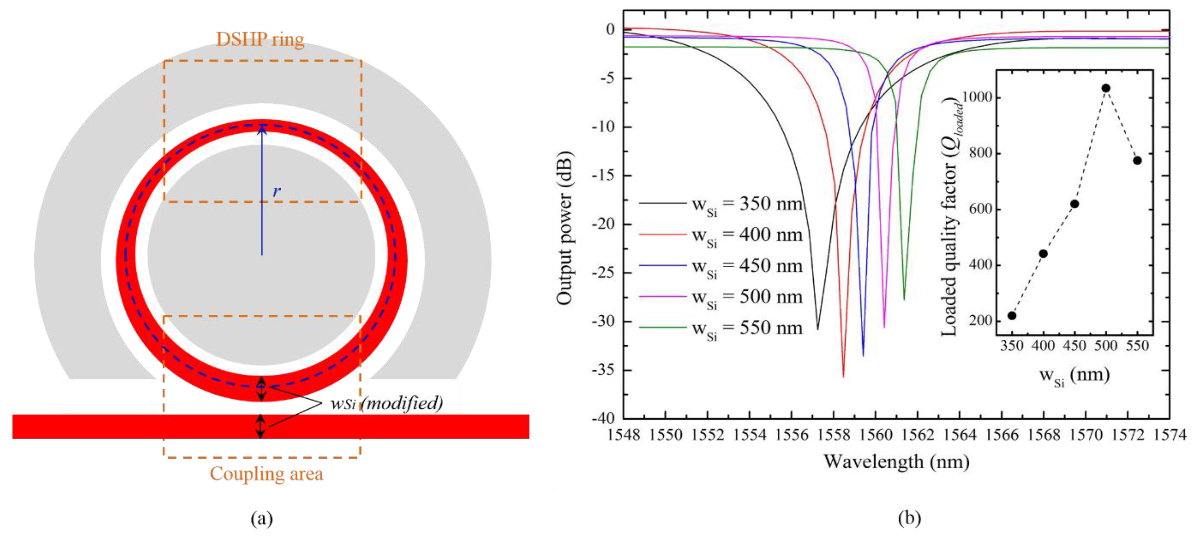
From the characterization results of the fabricated DSHP ring resonator, the loaded Q factor is much lower compared to the initial Qabs factor shown in Figure 2b, which is mainly due to the phase mismatch between the different propagation modes (open and closed areas of the DSHP ring), in other words, the mismatch of neff. In order to compensate for such a mismatch, the difference between the neff of these two areas needs to be reduced. Since the neff of the closed DSHP ring is higher than that of the partly open area with the same wSi due to better optical confinement, one can broaden the Si waveguide in the coupling area to get a higher Q factor, as shown in Figure 6a.
Figure 6. (a) Schematic of the modified double-slot hybrid plasmonic ring sensor. (b) Finite difference time domain (FDTD) simulation results of the modified DSHP ring sensor with different wSi(modified). The sub-figure shows the loaded Q factor as a function of wSi(modified).
Photonics 02 01116 g006
In the coupling area, the widths of the Si bus waveguide and the partly open DSHP ring are modified, denoted by wSi(modified). One needs to notice that the widths of the Si bus waveguide and the Si ridge of the open area of the DSHP ring have to be identical to achieve the phase match condition. The size and other parameters of the modified DSHP ring are similar to the fabricated one (wSi = 350 nm, wslot1 = 250 nm and wslot2 = 350 nm). In order to decrease the coupling loss, Si tapers are used to connect the coupling area to the DSHP ring area.
The simulation is done using the finite difference time domain (FDTD) method, where the geometry of the DSHP ring is fixed, and wSi(modified) increases from 350 nm to 550 nm. The transmission responses are shown in Figure 6b, where the different colors represent different wSi(modified). One can see that when wSi(modified) is around 500 nm, a maximum loaded Q factor is achieved (larger than 1000), which means that the neff of the DSHP ring and the coupling are nearly matched, and the coupling loss comes to the minimum value.

5. Discussion

For optical homogenous sensing applications, to measure the refractive index of liquids, the DSHP ring resonator shows high sensitivity to the infiltrating materials, giving a value as high as 687.5 nm/RIU as obtained experimentally. To further evaluate the performance of the DSHP ring sensor, a figure of merit (FOM) [31], defined by:
F O M = S Δ λ = S λ Q
expressing the number of linewidth shifts for an infiltrating material refractive index change of one unit, can be applied. From the experimental results, the FOM of the DSHP ring sensor is around 97.5, which can be increased to 466 after loaded Q factor modifications. The detection limit (DL), describing the smallest refractive index change that can be detected by the system, can be calculated by:
D L = f F O M
where f is a factor expressing the fraction of the resonance linewidth that can be resolved. The f factor is highly dependent on the performance of the detection system used. From [16], we can estimate this value as 1/400 to evaluate the property of the DSHP ring. The detection limit of the fabricated DSHP ring is around 2.57 × 10⁻⁵ RIU (5.37 × 10⁻⁶ RIU after loaded Q factor modification). Table 1 shows the comparisons between the fabricated DSHP ring sensor and other experimentally-demonstrated label-free ring sensors. Due to the high sensitivity of the DSHP ring, the DL after loaded Q factor modifications is low.
Table 1. Comparison between different kinds of ring-type label-free sensors (* results after loaded Q factor modifications).
Waveguide structureWidth × HeightRadiusQ FactorS (nm/RIU)DL (RIU)Reference
Si waveguide500 nm × 220 nm≈ 5 μm20,000703.75 × 10−6[2]
Si slot waveguide640 nm × 220 nm> 5 μm5002984.2 × 10−5[16]
SiN slot waveguide1150 nm × 250 70 μm1,800212.132.3 × 10−5[15]
DSHP waveguide950 nm × 250 nm6 μm300 (1034) *687.52.57 × 10−5
(5.37 × 10⁻⁶) *
This paper
Another promising application of the DSHP ring resonator is as electro-optic modulator. The high-sensitivity to material filling the slots will result in the high efficiency of modulating optical devices. Moreover, the overlap between optical and electronic signals leads to a less complex fabrication process (no extra electrodes are required), where the electric field can be large due to the narrow gap between two plasmonic sheets. The performance of an EO polymer-based DSHP ring resonator modulator can be calculated by employing a typical high-quality EO polymer with properties as n = 1.5 and r33 = 300 pm/V [32], and assuming 80% of the resonant peak shift is provided by the slot material. Based on the given experimental results, the modulation voltage,
V = 2 Δ n w s l o t n 3 r 33 = 2 w s l o t F O M n 3 r 33
for a 3-dB band shift is around 24 V. After loaded Q factor modification, it can decrease to as low a value as 5 V. The capacitance is estimated to be 0.245 fF, which is calculated from:
C = ε 0 ε E O P 2 π r h W G w
where 2πr·hWG is the average area of the capacitance formed by inner and outer Ag rings and w is the total width of the DSHP ring (w = wSi + wslot1 + wslot2). By taking a reasonable resistance of electronic circuits (below 1500 Ω from [12]), the resistor-capacitor (RC) time constant is above 2 THz. For photon lifetime limitation, estimated from the Q factor, the bandwidth can reach a value larger than 600 GHz. The power consumption, expressing the energy dissipation during the charge-discharge cycles, is given by:
W = 1 2 C V 2 f
According to the results given above, the power consumption is about 13.8 mW for 100-GHz modulation, which can decrease to 0.43 mW after loaded Q factor modification. The corresponding average power consumptions are 138 fJ/bit and 4.3 fJ/bit, respectively.

6. Conclusions

In this paper, we have experimentally demonstrated a DSHP ring resonator with ultra-high sensitivity to infiltrating materials, which shows the potential to be applied in homogeneous sensors and electro-optic polymer-based modulators.
Axisymmetric FEM simulations show that the Q factors of DSHP rings tend to their Qabs factors when the radius is large enough (larger than about 6 μm), where the waveguide absorption loss dominants the performance of the DSHP ring rather than radiation loss. Then, optimizations are made for Qabs factors by defining the q-parameter (q = wSi/w) as the occupancy of the photonics mode. Simulation results show that the Qabs factors for hybrid plasmonic-photonics mode (0 < q < 1) are much larger than that for a pure plasmonic slot waveguide (q = 0 or 1), as shown in Figure 2b, where the optimized Qabs factors can reach as high a value as 300,000 in theory (w = 1000 nm and q = 0.55). Due to the interactions of the hybrid photonic-plasmonic mode, optimal q-parameters for sensitivity are also observed, which can reach 700 nm/RIU (w = 500 nm and q = 0.35), as shown in Figure 2d.
Based on simulation results, a DSHP ring resonator with a Si access waveguide by opening a coupling area (partly without the outer Ag ring) is designed, whose fabrication process is compatible with conventional SOI technology. Experimental results show that the sensitivity to the refractive index change of infiltrating materials (100% and 80% aqueous solution of IPA) of the fabricated DSHP can reach as high a value as 687.5 nm/RIU. The sensitivity is about five-times larger than that of Si ring resonator without plasmonic materials (132.41 nm/RIU). The measured sensitivity is slightly higher than simulation results (~600 nm/RIU), which is due to the sensitive coupling area and fabrication-induced roughness. Besides, the loaded Q factor of the DSHP ring is low (~300), which is mainly caused by the coupling loss between open and closed areas of the ring. In order to compensate for the coupling loss, as shown in Figure 6a, one can broaden the width of the Si ridge at the coupling area to decrease the difference of neff between open and closed areas of the DSHP ring. FDTD simulation results show that the modified Q factor can be over 1000, when phase matching is achieved, as shown in Figure 6b.
Compared to other experimentally-demonstrated types of optical ring sensors (Table 1), the fabricated DSHP ring has higher sensitivity and quite a low detection limit, which can be applied in advanced optical homogeneous sensors. Moreover, the special structure of the DSHP ring resonator is also promising for high-speed electro-optic modulator applications. Two plasmonic sheets can be used as electrodes with very low capacitance (~0.245 fF), and the narrow slot (less than 1 μm) can provide quite a large electric field. Taking the reasonable parameters of the electro-optic polymer, the applied voltage for a 3-dB band shift is about 5 V after loaded Q factor optimization, and the average energy consumption can reach as low value as 4.3 fJ/bit.

Acknowledgments

This work was supported by “the Swedish Research Council (VR) through its Linnæus Center of Excellence ADOPT”. Xu Sun acknowledges China Scholarship Council (CSC) for the financial support.

Author Contributions

Xu Sun has done the design, performed the experiments and wrote the first manuscript; all the authors have discussed the problems and formulated the content.

Conflicts of Interest

The authors declare no conflict of interest.

References

  1. Soref, R.A. Silicon-based optoelectronics. Proc. IEEE 1993, 81, 1687–1706. [Google Scholar] [CrossRef]
  2. De Vos, K.; Bartolozzi, I.; Schacht, E.; Bienstman, P.; Baets, R. Silicon-on-insulator microring resonator for sensitive and label-free biosensing. Opt. Express 2007, 15, 7610–7615. [Google Scholar] [CrossRef] [PubMed]
  3. Densmore, A.; Xu, D.-X.; Waldron, P.; Janz, S.; Cheben, P.; Lapointe, J.; Delâge, A.; Lamontagne, B.; Schmid, J.; Post, E. A silicon-on-insulator photonic wire based evanescent field sensor. IEEE Photon. Technol. Lett. 2006, 18, 2520–2522. [Google Scholar] [CrossRef]
  4. Dong, P.; Liao, S.; Feng, D.; Liang, H.; Zheng, D.; Shafiiha, R.; Kung, C.-C.; Qian, W.; Li, G.; Zheng, X. Low Vpp, ultralow-energy, compact, high-speed silicon electro-optic modulator. Opt. Express 2009, 17, 22484–22490. [Google Scholar] [CrossRef] [PubMed]
  5. Wangüemert-Pérez, G.J.; Cheben, P.; Ortega-Moñux, A.; Alonso-Ramos, C.; Pérez-Galacho, D.; Halir, R.; Molina-Fernández, I.; Xu, D.-X.; Schmid, J.H. Evanescent field waveguide sensing with subwavelength grating structures in silicon-on-insulator. Opt. Lett. 2014, 39, 4442–4445. [Google Scholar] [CrossRef] [PubMed]
  6. Jin, L.; Li, M.; He, J.-J. Highly-sensitive silicon-on-insulator sensor based on two cascaded micro-ring resonators with vernier effect. Opt. Commun. 2011, 284, 156–159. [Google Scholar] [CrossRef]
  7. Li, G.; Zheng, X.; Yao, J.; Thacker, H.; Shubin, I.; Luo, Y.; Raj, K.; Cunningham, J.E.; Krishnamoorthy, A.V. 25 Gb/s 1V-driving CMOS ring modulator with integrated thermal tuning. Opt. Express 2011, 19, 20435–20443. [Google Scholar] [CrossRef] [PubMed]
  8. Li, H.; Fan, X. Characterization of sensing capability of optofluidic ring resonator biosensors. Appl. Phys. Lett. 2010, 97. [Google Scholar] [CrossRef]
  9. Liu, A.; Jones, R.; Liao, L.; Samara-Rubio, D.; Rubin, D.; Cohen, O.; Nicolaescu, R.; Paniccia, M. A high-speed silicon optical modulator based on a metal–oxide–semiconductor capacitor. Nature 2004, 427, 615–618. [Google Scholar] [CrossRef] [PubMed]
  10. Wang, J.; Dai, D. Highly sensitive si nanowire-based optical sensor using a Mach–Zehnder interferometer coupled microring. Opt. Lett. 2010, 35, 4229–4231. [Google Scholar] [PubMed]
  11. Xu, Q.; Manipatruni, S.; Schmidt, B.; Shakya, J.; Lipson, M. 12.5 gbit/s carrier-injection-based silicon micro-ring silicon modulators. Opt. Express 2007, 15, 430–436. [Google Scholar] [CrossRef] [PubMed]
  12. Alloatti, L.; Korn, D.; Palmer, R.; Hillerkuss, D.; Li, J.; Barklund, A.; Dinu, R.; Wieland, J.; Fournier, M.; Fedeli, J. 42.7 gbit/s electro-optic modulator in silicon technology. Opt. Express 2011, 19, 11841–11851. [Google Scholar] [CrossRef] [PubMed]
  13. Yamada, H.; Chu, T.; Ishida, S.; Arakawa, Y. Si photonic wire waveguide devices. IEEE J. Sel. Top. Quantum Electron. 2006, 12, 1371–1379. [Google Scholar] [CrossRef]
  14. Schmidt, H.; Yin, D.; Barber, J.P.; Hawkins, A.R. Hollow-core waveguides and 2-d waveguide arrays for integrated optics of gases and liquids. IEEE J. Sel. Top. Quantum Electron. 2005, 11, 519–527. [Google Scholar] [CrossRef]
  15. Barrios, C.A.; Gylfason, K.B.; Sánchez, B.; Griol, A.; Sohlström, H.; Holgado, M.; Casquel, R. Slot-waveguide biochemical sensor. Opt. Lett. 2007, 32, 3080–3082. [Google Scholar] [CrossRef] [PubMed]
  16. Claes, T.; Molera, J.G.; de Vos, K.; Schacht, E.; Baets, R.; Bienstman, P. Label-free biosensing with a slot-waveguide-based ring resonator in silicon on insulator. IEEE Photon. J. 2009, 1, 197–204. [Google Scholar] [CrossRef]
  17. Liu, Q.; Tu, X.; Kim, K.W.; Kee, J.S.; Shin, Y.; Han, K.; Yoon, Y.-J.; Lo, G.-Q.; Park, M.K. Highly sensitive Mach–Zehnder interferometer biosensor based on silicon nitride slot waveguide. Sens. Actuators B Chem. 2013, 188, 681–688. [Google Scholar] [CrossRef]
  18. Prieto, F.; Sepulveda, B.; Calle, A.; Llobera, A.; Domínguez, C.; Abad, A.; Montoya, A.; Lechuga, L.M. An integrated optical interferometric nanodevice based on silicon technology for biosensor applications. Nanotechnology 2003, 14, 907–912. [Google Scholar] [CrossRef]
  19. Wang, X.; Grist, S.; Flueckiger, J.; Jaeger, N.A.; Chrostowski, L. Silicon photonic slot waveguide Bragg gratings and resonators. Opt. Express 2013, 21, 19029–19039. [Google Scholar] [CrossRef] [PubMed]
  20. Melikyan, A.; Alloatti, L.; Muslija, A.; Hillerkuss, D.; Schindler, P.; Li, J.; Palmer, R.; Korn, D.; Muehlbrandt, S.; van Thourhout, D. High-speed plasmonic phase modulators. Nat. Photon. 2014, 8, 229–233. [Google Scholar] [CrossRef]
  21. Dai, D.; He, S. Low-loss hybrid plasmonic waveguide with double low-index nano-slots. Opt. Express 2010, 18, 17958–17966. [Google Scholar] [CrossRef] [PubMed]
  22. Sun, X.; Dai, D.; Thylén, L.; Wosinski, L. High-sensitivity liquid refractive-index sensor based on a Mach-Zehnder interferometer with a double-slot hybrid plasmonic waveguide. Opt. Express 2015, 23, 25688–25699. [Google Scholar] [CrossRef] [PubMed]
  23. Oxborrow, M. Traceable 2-D finite-element simulation of the whispering-gallery modes of axisymmetric electromagnetic resonators. IEEE Trans. Microw. Theory Tech. 2007, 55, 1209–1218. [Google Scholar] [CrossRef]
  24. Wei, T.; Han, Y.; Li, Y.; Tsai, H.-L.; Xiao, H. Temperature-insensitive miniaturized fiber inline Fabry-Perot interferometer for highly sensitive refractive index measurement. Opt. Express 2008, 16, 5764–5769. [Google Scholar] [CrossRef] [PubMed]
  25. Bohren, C.F.; Huffman, D.R. Absorption and scattering of light by small particles; John Wiley & Sons: Weinheim, Germany, 2008. [Google Scholar]
  26. Sun, X.; Wosinski, L.; Thylen, L. Nanoscale surface plasmon polariton disk resonators, a theoretical analysis. IEEE J. Sel. Top. Quantum Electron. 2016, 22. [Google Scholar] [CrossRef]
  27. Lou, F.; Dai, D.; Thylen, L.; Wosinski, L. Design and analysis of ultra-compact EO polymer modulators based on hybrid plasmonic microring resonators. Opt. Express 2013, 21, 20041–20051. [Google Scholar] [CrossRef] [PubMed]
  28. Saleh, B.E.; Teich, M.C. Resonator Optics in Fundamentals of Photonics; John Wiley & Sons: New York, NY, USA, 1991. [Google Scholar]
  29. Tang, Y.; Wang, Z.; Wosinski, L.; Westergren, U.; He, S. Highly efficient nonuniform grating coupler for silicon-on-insulator nanophotonic circuits. Opt. Lett. 2010, 35, 1290–1292. [Google Scholar] [CrossRef] [PubMed]
  30. Lide, D.R. CRC Handbook of Chemistry and Physics; CRC Press: Boca Raton, FL, USA, 2004. [Google Scholar]
  31. Sherry, L.J.; Jin, R.; Mirkin, C.A.; Schatz, G.C.; van Duyne, R.P. Localized surface plasmon resonance spectroscopy of single silver triangular nanoprisms. Nano Lett. 2006, 6, 2060–2065. [Google Scholar] [CrossRef] [PubMed]
  32. Dalton, L.; Robinson, B.; Jen, A.; Ried, P.; Eichinger, B.; Sullivan, P.; Akelaitis, A.; Bale, D.; Haller, M.; Luo, J. Electro-optic coefficients of 500 pm/v and beyond for organic materials. Proc. SPIE 2005, 5935. [Google Scholar] [CrossRef]