Article

A Bidirectional Controllable Terahertz Multifunctional Device Based on Graphene-Vanadium Dioxide

1
School of Waterford Institute, Nanjing University of Information Science and Technology, Nanjing 210044, China
2
School of Electronics and Information Engineering, Nanjing University of Information Science and Technology, Nanjing 210044, China
3
School of Integrated Circuits, Nanjing University of Information Science and Technology, Nanjing 210044, China
*
Author to whom correspondence should be addressed.
Photonics 2026, 13(9), 852; https://doi.org/10.3390/photonics13090852
Submission received: 28 July 2026 / Revised: 30 August 2026 / Accepted: 3 September 2026 / Published: 9 September 2026
(This article belongs to the Special Issue Metasurfaces for Next‑Generation Nanophotonic Devices)

Abstract

A bidirectional controllable terahertz multifunctional device based on graphene and vanadium dioxide is proposed in this paper. By adjusting the phase transition characteristics of vanadium dioxide and the chemical potential of graphene, the bidirectional transmission of electromagnetic waves is regulated to achieve multiple functions. When vanadium dioxide is in its metallic state, the device exhibits circular dichroism at 5.65 THz for the forward left- and right-circularly polarized waves. For the backward-propagating electromagnetic waves, when the chemical potential of graphene is 1 eV and 0 eV, the device shows broadband absorption and broadband orthogonal polarization conversion, respectively. The relative bandwidths are 101.1% and 126.3%, respectively. When vanadium dioxide is in its insulating state, the device exhibits an obvious asymmetric transmission effect on left- and right-circularly polarized light at 1.66 THz and 3.1 THz. The proposed metasurface is expected to expand the application of terahertz technology and has broad prospects in the fields of 6G mobile communication, high-capacity information processing, environmental and food detection.

1. Introduction

Terahertz waves have significant application potential in terahertz communication, security screening, atmospheric and environmental monitoring, biomedical detection and imaging, radar detection, and other fields because of their technical characteristics of low energy, broad bandwidth and strong penetration [1]. However, natural materials respond weakly to terahertz waves, which seriously hinders the development of terahertz technology [2]. In recent years, metamaterials have received wide attention for their unique optical properties [3], such as perfect absorption [4,5], bound states in the continuum [6,7,8] and an efficient optocoupler [9,10,11]. The emergence of metamaterials has overcome the limitation of terahertz waves lacking corresponding responsive materials, creating broad opportunities for the development of terahertz devices [12,13]. Terahertz devices based on metamaterials have been widely studied in the fields of absorption [14,15,16], polarization [17], coding [18], waveform modulation [19], and so on.
With the development of metamaterial devices, the research of integrating multiple functions such as absorption and polarization conversion into the same device has more application prospects [20]. At the same time, introducing dynamic control into integrated devices further enhances their performance [21,22]. In 2021, Li et al. [23] proposed a reflective multifunctional metasurface based on graphene and photosensitive silicon. By adjusting the pump-light intensity and the chemical potential of graphene, three functions of broadband absorption and broadband orthogonal line- and circular-polarization conversion in terahertz bands can be achieved. In 2022, Qiu et al. [24] proposed a multifunctional device based on hexagonal VO2 and metal gratings. Broadband absorption, orthogonal linear-polarization conversion, line-to-circular polarization conversion and total reflection can be realized by using the phase transition characteristics of VO2. In 2025, Zhao et al. [25] proposed a hybrid metasurface composed of vanadium dioxide and graphene, which uses the phase transition of VO2 and the Fermi level of graphene to achieve broadband absorption orthogonal linear-polarization conversion and line-to-circular polarization conversion.
On the other hand, studies of terahertz wave polarization also involve singular phenomena caused by selective transmission, the reflection and absorption of polarization states, such as circular dichroism (CD) [26], asymmetric transmission (AT) [27], and so on. In 2021, Ren et al. [28] proposed a multifunctional terahertz metamaterial device based on VO2. Perfect absorption and broadband AT were achieved before and after VO2 phase transition. In 2024, Qureshi et al. [29] used VO2 as a phase-change medium in a mixed metasurface. By adjusting the conductivity of different vanadium dioxide layers, the metasurface can realize a variety of terahertz device functions, including single-band perfect terahertz absorption, circular dichroism (CD) effects in the reflection and transmission fields, and an electromagnetically induced transparency (EIT) effect. In 2025, Wu et al. [30] designed a flexible and reversible tunable terahertz broadband polarization converter that switches between transmission mode and reflection mode based on the temperature-controlled phase-transition characteristics of vanadium dioxide. When vanadium dioxide is in the insulating state, transmission polarization conversion (TPC) can be realized, and ideal broadband linear-to-linear (LTL) polarization conversion can be obtained. When vanadium dioxide is in its metallic state, reflection polarization conversion (RPC) can be achieved, and relatively perfect linear-to-right-handed circular polarization (LTRHCP) and linear-to-left-handed circular polarization (LTLHCP) conversion can be realized in different frequency bands.
Above all, although much of the graphene VO2 hybrid terahertz metasurface has been studied, most reported configurations are limited to dual-mode switches, the bandwidth of absorption or polarization conversion is limited, and only unidirectional incidence is supported.
In this work, we propose a reconfigurable multifunctional metasurface. The device has bidirectional incidence, four functions and ultra-wide absorption and polarization conversion bands. By adjusting the phase transition characteristics of vanadium dioxide and the chemical potential of graphene, four functions can be realized in the terahertz band: circular dichroism, linearly polarized light broadband absorption, ultra-wideband orthogonal polarization conversion, and asymmetric transmission. Among these, the broadband absorption rate exceeds 0.9 over a 2.68–8.16 THz range, while the orthogonal linear polarization conversion rate is greater than 0.9 over a 1.6–7.08 THz range. The relative bandwidth is as high as 126.3%.

2. Structural Model Design

The structure of the terahertz multifunctional device based on graphene and VO2 is shown in Figure 1. The structural unit is composed of a Au-VO2 composite layer, polytetrafluoroethylene (PTFE), VO2 film, PTFE, VO2 film, a metal wire grid, PTFE, graphene film, PTFE, a Au-VO2 composite layer, PTFE, and graphene film from top to bottom. The open square ring and metal wire grid are made of gold (Au), and the conductivity is 4.561 × 10⁷ S/m. The dielectric layer is made of PTFE, with a relative dielectric constant of 2.1 and a loss tangent of 0.0002 [31]. The surface conductivity of graphene is composed of in-band conductivity and inter-band conductivity. It can be expressed in the form of the Kubo equation [32]:
σ ( ω , Γ , μ c , T ) = σ intra ( ω , Γ , μ c , T ) + σ inter ( ω , Γ , μ c , T ) = - i e 2 π 2 ( ω + i 2 Γ ) 0 ε f d ( ε ) ε - f d ( - ε ) ε d ε + i e 2 ( ω + i 2 Γ ) π 2 0 f d ( - ε ) - f d ( ε ) ( ω + i 2 Γ ) 2 - 4 ε / 2 d ε
Among these, f d ( ε ) = 1 / ( e x p ( ( ε μ C ) / k B T ) + 1 ) , ω is the angular frequency of electromagnetic waves, kB is the Boltzmann constant, is the reduced Planck constant, T is the Kelvin temperature, and e, Γ, and μ C are the electronic charge, scattering rate, and chemical potential of graphene, respectively. Among these, the scattering rate is Γ = ћ/(2τ) and τ is the relaxation time of graphene. In the terahertz band, ω μ C , μ C k B T , σ i n t r a σ i n t e r , and the conductivity of graphene is approximately equal to the in-band conductivity [33]:
σ ( ω , Γ , μ c , T ) σ intra ( ω , Γ , μ c , T ) = i e 2 k B T π 2 ( ω + i 2 Γ ) ln ( 2 cos h ( μ c 2 k B T ) )
In Formula (2), the scattering rate of graphene is set to 8 meV, and the chemical potential is set to 1 eV.
In the terahertz band, the optical dielectric constant of VO2 can be described by the Drude model [34]:
ε V O 2 ω = ε ω p 2 σ ω 2 + i γ ω
Among these, ε , ω p ( σ 0 ) and γ represent the high-frequency dielectric constant, plasma frequency and collision frequency, respectively. In addition, ω p ( σ ) , σ are proportional to the free carrier density and ω p 2 ( σ ) = ( σ / σ 0 ) ω p 2 ( σ 0 ) is used to indicate the plasma frequency. Among these, ε = 12 , σ 0 = 3 × 10 5 S / m , ω p ( σ 0 ) = 1.4 × 10 5 r a d / s , γ = 5.75 × 10 15 r a d / s . The conductivity of VO2 in its insulating and metallic states is 20 S/m and 2 × 10⁵ S/m, respectively [35].
In order to analyze the related functions of the metamaterial device designed in this paper, the finite-difference time-domain (FDTD) method is used to simulate the structure in the 0.10 THz frequency band. In the calculations, the spatial mesh cell is set to x = y = z = s = 100 n m and the time step is taken as t = s / 2 c = 3.33 × 10 17 s . The x-axis and y-axis directions are set as periodic boundary conditions, and the z-axis is set as an open boundary condition. The plane light is transmitted along the +z or −z axis in the entire structure. The electromagnetic waves transmitted along the +z and −z axes are defined as reverse transmission and forward transmission, respectively. The specific structural parameters are shown in Table 1.
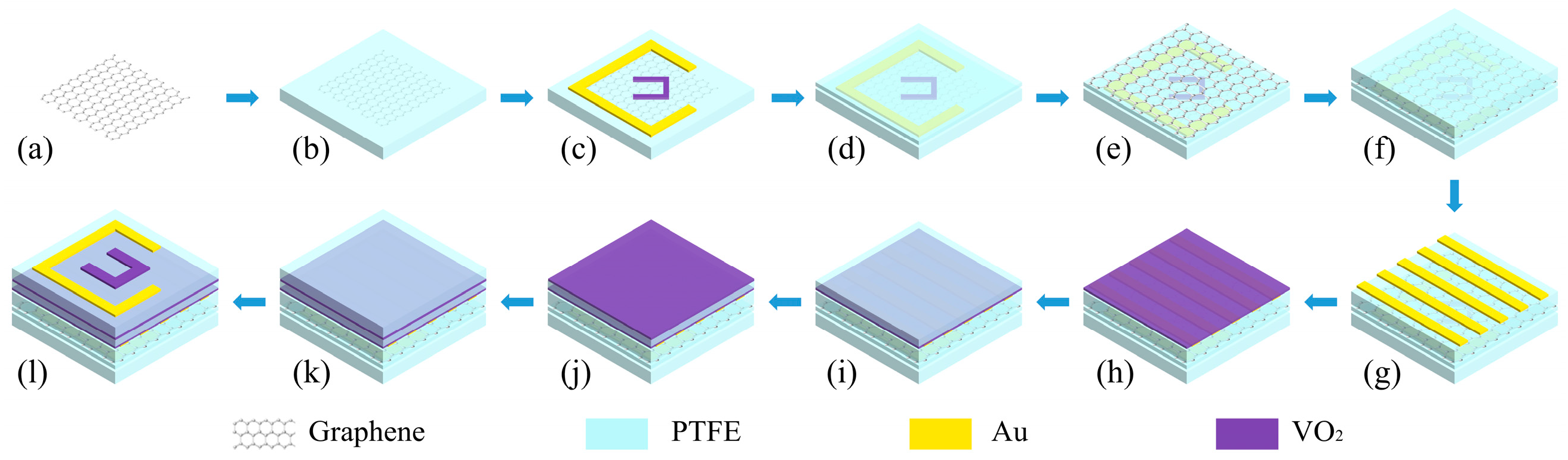
A possible setup for constructing the optimized multifunctional metasurface is presented in Figure 2: (a) CVD grown graphene was pre-patterned on a Cu substrate via electron beam lithography, O2 plasma reactive ion etching, and resist stripping. (b) After Cu foil etching, the pre-patterned graphene was dry transferred onto PTFE spacers with a PDMS stamp. (c) The structure of the nested Au VO2 can be prepared by a two-step aligned EBL lift-off process. (d) Deposition of PTFE can be achieved by a plasma-enhanced chemical vapor deposition (PECVD) process. (e) The graphene layer can be grown by chemical vapor deposition (CVD) followed by transfer to the PTFE layer. (f) Deposition of PTFE is achieved by a plasma-enhanced chemical vapor deposition (PECVD) process. (g) The gold wire grid is obtained by lithography and metallization. (h) The VO2 pattern is formed by a stripping and annealing process. (i) Deposition of PTFE is achieved by a plasma-enhanced chemical vapor deposition (PECVD) process. (j) The VO2 pattern is formed by a stripping and annealing process. (k) Deposition of PTFE is achieved by a plasma-enhanced chemical vapor deposition (PECVD) process. (l) The structure of the nested Au VO2 can be prepared by a two-step aligned EBL lift-off process. To modulate the tunable response of the multifunctional metasurface, its temperature can be elevated by a non-contact heating device [36].

3. Functional Analysis of Bidirectional Controllable Terahertz Multifunctional Devices

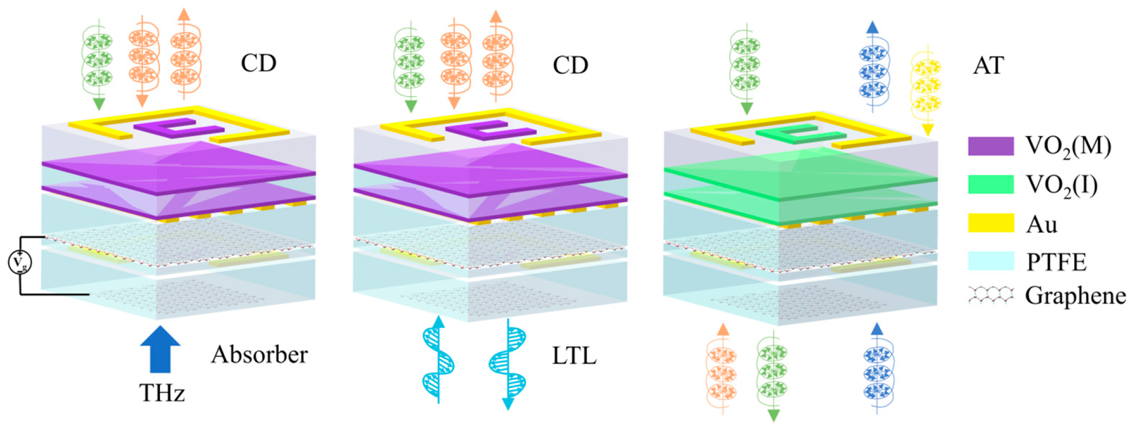
Figure 3 shows the function of the multifunctional device during forward and reverse transmission of electromagnetic waves under different states of graphene and VO2. It can be observed that, when VO2 is in its metallic state and graphene is set to a chemical potential of 1 eV, the device exhibits differential absorption of forward-propagating circularly polarized light and broadband absorption of reverse-propagating plane waves. When VO2 is in its metallic state and the chemical potential of graphene is 0 eV, the device exhibits differential absorption of forward-propagating circularly polarized light, and the reverse-propagating linearly polarized wave is converted into its orthogonal polarization component over a broadband range. When VO2 is in the insulating state and the chemical potential of graphene is 0 eV, the device produces an AT effect for circularly polarized light in the forward and reverse directions.

3.1. Circular Dichroism

When VO2 is in its metallic state, the first layer of the VO2 film blocks the transmission of electromagnetic waves propagating in the negative z-direction (−z). Therefore, when the electromagnetic wave propagates in the positive direction, the absorption rate can be expressed as A = 1 − R. For forward-propagating left-circularly polarized (LCP) and right-circularly polarized (RCP) waves, the absorptivity can be expressed as [37]:
A L C P = 1 R L C P
A R C P = 1 R R C P
Circular dichroism (CD) refers to the difference in the absorption of left-circularly polarized (LCP) and right-circularly polarized (RCP) light, which can be expressed as follows:
C D = A L C P A R C P
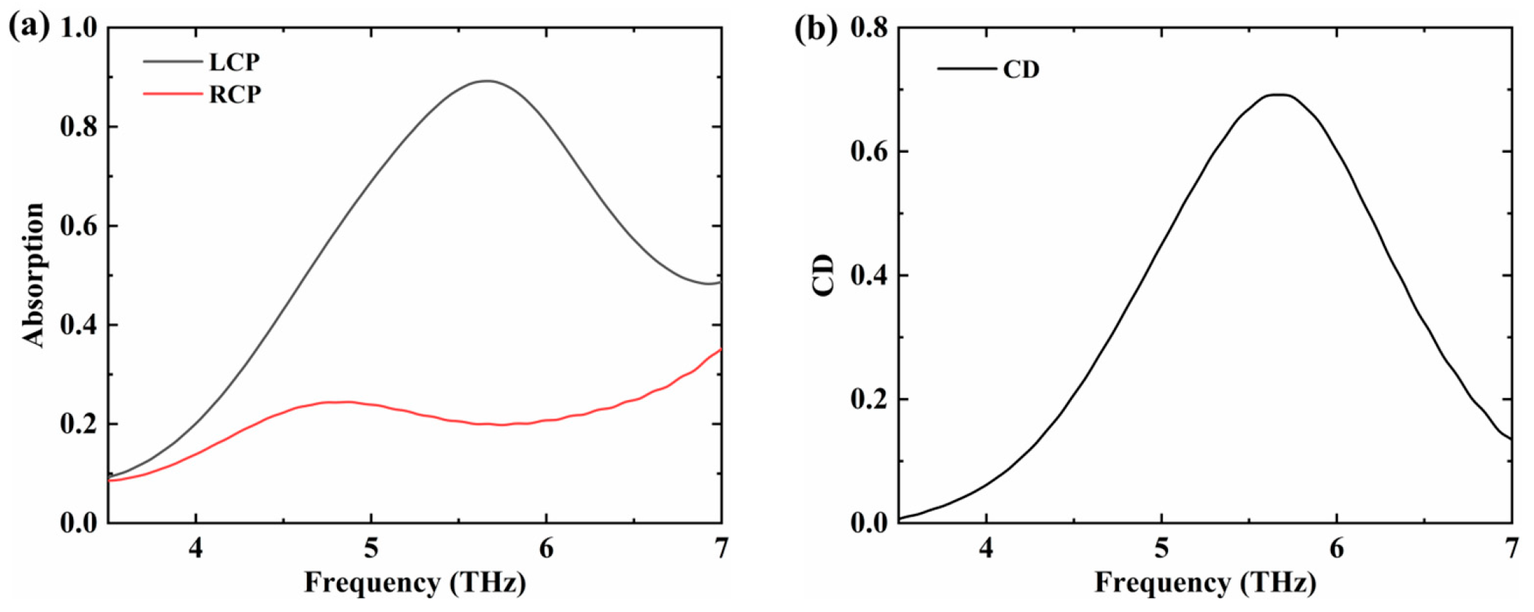
Figure 4 shows the absorption spectrum and CD values of LCP and RCP under forward transmission. It can be found that at 5.65 THz, the metamaterial device has a strong absorption of LCP, reaching 89%, and the absorption rate of RCP is only 20%. Therefore, an obvious CD response is generated, and the CD value is 0.69.
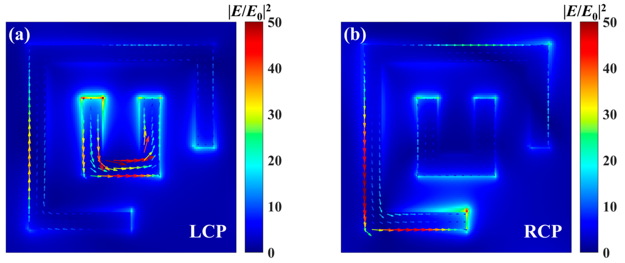
Figure 5 shows the surface electric field intensity and current vector distribution of the upper Au-VO2 composite structure at 5.65 THz when LCP and RCP are transmitted forward. As shown in Figure 5a, when the LCP is incident, a pronounced electric dipole resonance occurs at the openings on both sides of the inner split ring, and the surface current is significantly enhanced, resulting in a higher absorption rate. In contrast, Figure 5b shows that, when RCP is incident, only one side of the outer split ring exhibits unipolar resonance, and the surface current is weak; therefore, the absorption rate is low [38].

3.2. Broadband Absorption

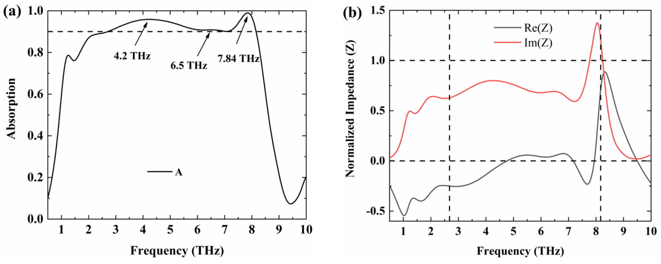
When VO2 is in its metallic state and the chemical potential of graphene is 1 eV, the device exhibits broadband absorption for a reversely transmitted plane wave. Figure 6a shows the absorption of x-polarized light in the 0.5–10 THz range. In the 2.68–8.16 THz range, the absorption rate exceeds 90%, and the relative bandwidth reaches 101.1%. Figure 6b shows the equivalent impedance of the device during reverse transmission. In the 2.68–8.16 THz range, the real part of the equivalent impedance Zeff fluctuates around 1, while the imaginary part of Zeff fluctuates around 0. According to the impedance matching theory [39], the equivalent impedance is matched to free-space impedance in the range of 2.68–8.16 THz, thereby achieving broadband absorption.
The VO2 film acts as a reflector when it is in a metallic state, so the transmittance is zero during the reverse transmission of light. The analysis of the broadband absorption of the device mainly focuses on the region below the second VO2 layer.
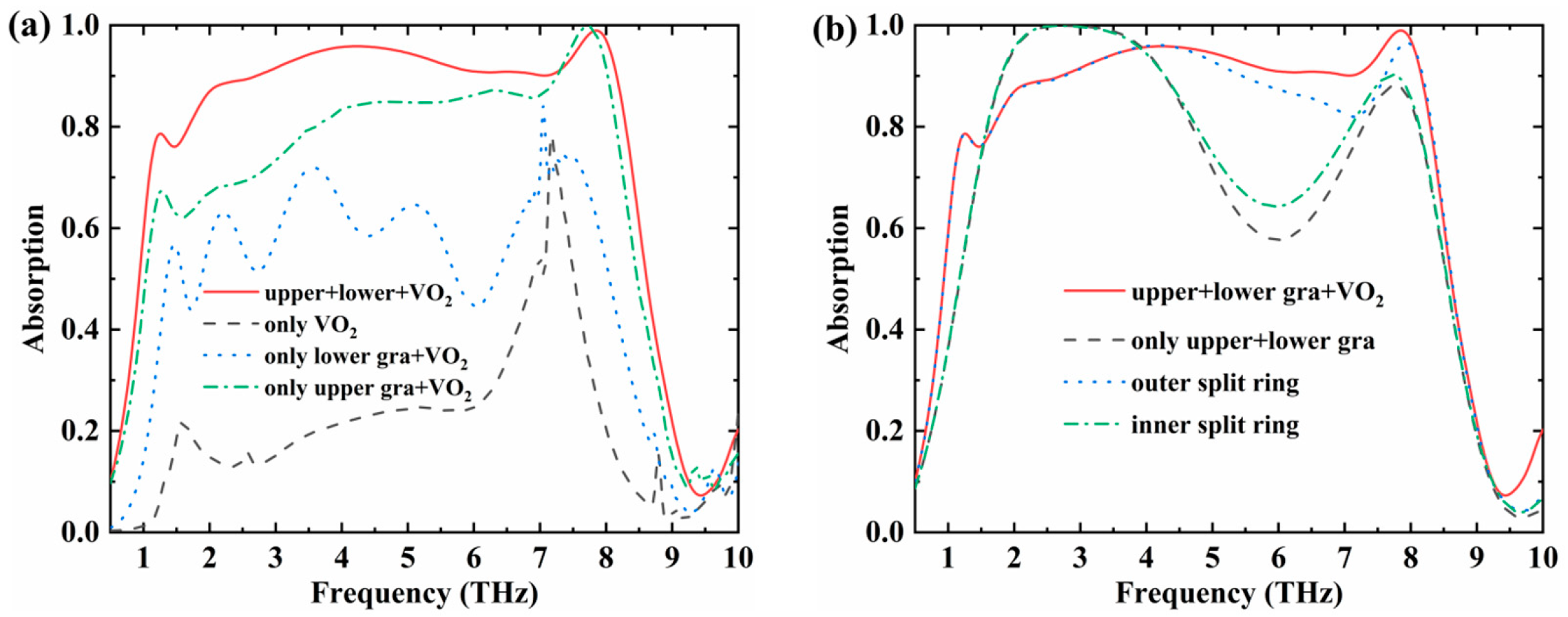
Figure 7a shows the effect of the graphene layer on the absorption spectrum. For a single-layer Au-VO2 composite structure, the structure is symmetrical along the 45° axis. Therefore, for x-polarized waves, the layer structure mainly acts as a polarization converter, producing only one absorption peak near 7.2 THz with an absorption rate of 78%. Adding either the upper or lower graphene layer significantly increases the absorption rate in the 1–7 THz range. When both graphene layers are present, the absorption rate in the 1–7 THz range improves further, and an absorption rate of more than 90% is achieved over the 2.68–8.16 THz range. These results indicate that the graphene layers play an important role in broadband absorption.
Figure 7b shows the influence of the inner and outer open rings in the Au–VO2 composite structure on the absorption spectrum, considering three cases: only the inner open ring, only the outer open ring, and both open rings. The absorption spectra for the outer split ring alone and for the double split ring are broadly consistent. Only in the high-frequency range of 7–8 THz does the double split ring show a further improvement in absorption, mainly because of its smaller size. The inner split ring is coupled to the outer split ring to a certain extent, which enhances absorption at high frequencies. In the case of only the inner split ring, the absorption is higher in the range of 1.5–4 THz and lower in the range of 4–8 THz than in the case of both split rings. This is mainly because, when only the inner open ring exists, its small size leads to very low electromagnetic resonance energy during the propagation of the electromagnetic wave. As a result, the absorption in this case is mainly determined by the two layers of graphene.
Figure 7b also shows the absorption spectrum of the Au-VO2 composite structure when the inner and outer split rings are not considered, which is roughly consistent with the spectrum obtained when only the inner split rings are considered. In the case where both the inner and outer split rings are absent, the absorption is mainly determined by the two graphene layers. The different side lengths of the graphene layers correspond to different resonant frequencies. Therefore, high absorption over a broad bandwidth can be achieved in the 2–4 THz range. The strong absorption near 8 THz is mainly caused by the coupling resonance between the two graphene layers. When the outer split ring is added, its 45° symmetry gives it polarization-conversion properties, and the increased number of layers changes the interlayer coupling, which affects the transmission and reflection of the incident light. As a result, low-frequency absorption is suppressed to some extent.
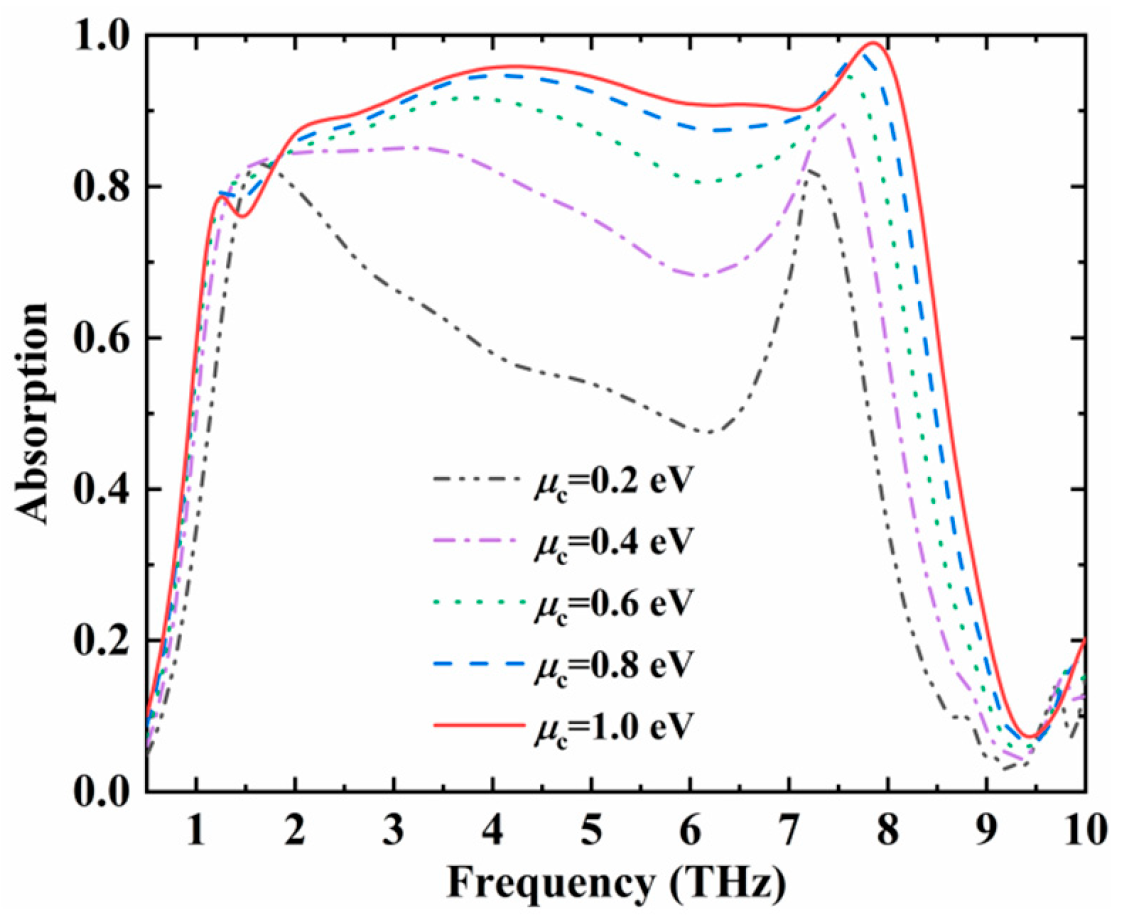
Figure 8 shows the influence of the chemical potential of graphene on the absorption spectra. As the chemical potential of graphene gradually increases from 0.2 eV to 1 eV, the increase of the absorption rate gradually slows down, and the high-frequency absorption resonance shows a relatively obvious blue shift. The phenomenon of blue shift can be explained by the relationship between the resonance frequency and the chemical potential of graphene. The resonant frequency of the absorber has the following relationship with the chemical potential of graphene [40]:
f α 0 μ c 2 π 2 c 1 / 2
Among these, α 0 is the structural constant of graphene. Therefore, as the chemical potential μ C increases, the resonant frequency gradually blue-shifts, and the trend of the resonant frequency at high frequencies satisfies this rule. Meanwhile, the low-frequency absorption is dominated by the broadband Fabry–Pérot (F–P) cavity formed by the multilayer composite structure composed of metal, VO2 and graphene [41]. Although the main plasmon mode blue-shifts, the real-part conductivity of graphene—and thus ohmic loss—rises markedly at low frequencies. This loss, superposed on the F–P cavity tail, significantly enhances non-resonant absorption and extends the low-frequency boundary, thereby broadening the overall absorption band.
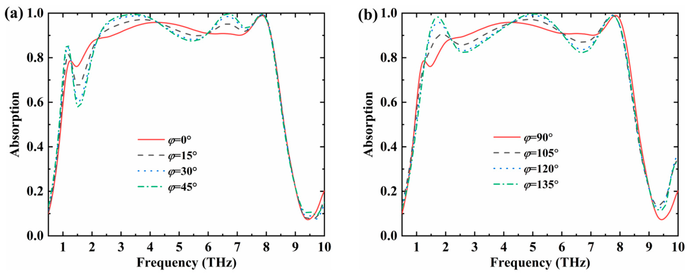
Since the Au-VO2 composite layer does not satisfy the C4 symmetry characteristic, the change of the polarization angle will have a certain effect on the absorption line. Figure 9 shows the change of the absorption line when the polarization angle of the incident polarized light increases from 0° to 45° and from 90° to 180°. Here, the polarization angle is defined as the angle between the polarization direction and the x-axis. As the polarization angle changes, the frequency range covered by the absorption spectrum remains almost unchanged. When the polarization angle changes from 0° to 45° or from 90° to 135°, the absorption trends in the intermediate frequency band are opposite; however, the structure still maintains high absorption over a stable bandwidth overall. When the polarization angle is 135°, the absorption rate remains above 80% over the range of 1.3–8.23 THz, with a relative bandwidth of 145.4%.

3.3. Broadband Orthogonal Polarization Conversion

When VO2 is in its metallic state and the chemical potential of graphene is 0 eV, the device exhibits broadband orthogonal polarization conversion for backward propagating linearly polarized or circularly polarized waves. In a metallic state, the VO2 thin film acts as a reflector, so the transmittance is zero during reverse light transmission. The device’s broadband orthogonal polarization conversion mainly occurs below the second VO2 thin-film layer.
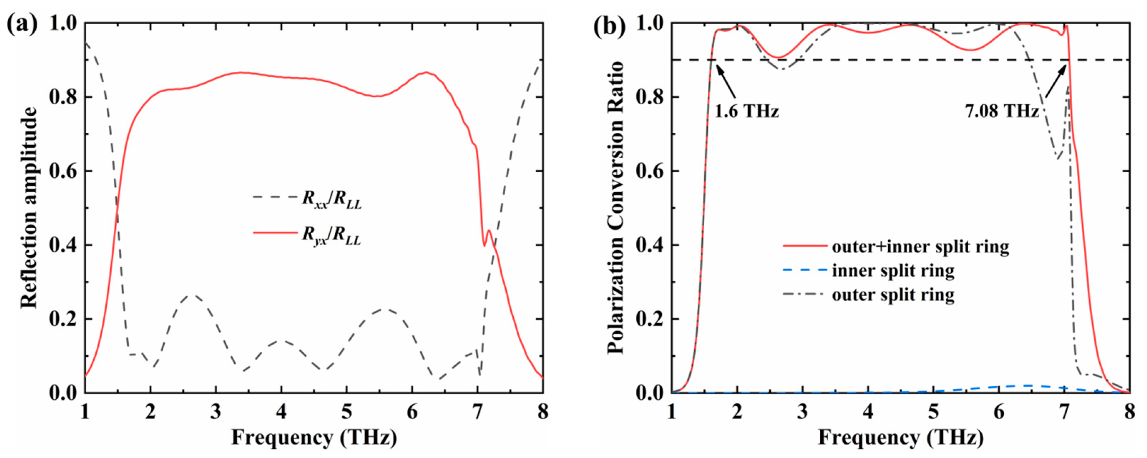
When the electric field of the incident light is aligned with the x-polarization direction, the co-polarization reflection coefficients Rxx (co-planar polarization reflection coefficient), the cross-polarization reflection coefficients Ryx (cross-polarization reflection coefficient), and the polarization conversion ratio (PCR) [42] are shown in Figure 10a. In the 2–6.6 THz range, Ryx is greater than 0.8. In the range of 1.57–7.12 THz, Rxx is less than 0.26. In the 1.6–7.08 THz range, the PCR exceeds 90% with a bandwidth of 5.48 THz and a relative bandwidth of 126.3%. Especially at 2.04 THz, 3.41 THz, 4.64 THz and 6.39 THz, Rxx reaches its minimum value, and Ryx is higher. At these frequencies, the PCR is approximately 100%. In addition, Figure 10b also shows the influence of the inner and outer split rings on polarization conversion. It is shown that broadband polarization conversion is mainly achieved by the outer split ring, whereas the inner split ring alone produces almost no orthogonal polarization component. However, combining the inner and outer split rings further enhances the polarization conversion efficiency at high frequencies and expands the operating bandwidth.
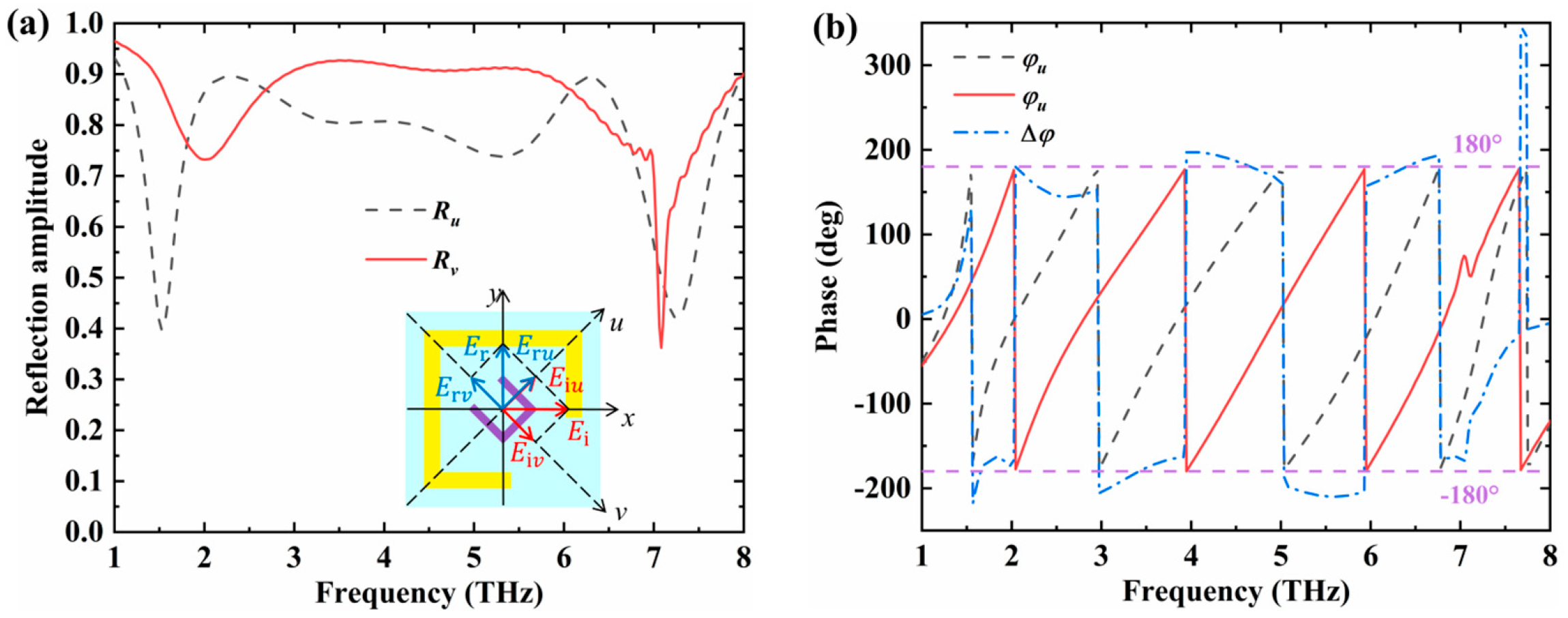
The realization of polarization conversion can be analyzed from the perspective of vector decomposition of electromagnetic waves. Based on the equivalent medium theory of metasurfaces, the device can be regarded as an anisotropic material [43]. Through the amplitude and phase distributions of the two orthogonal components of electromagnetic waves, the mechanism of polarization conversion can be further explained. An x-polarized wave can be decomposed into components with equal amplitude and phase along the u and v directions. If the reflected wave has the same amplitude in these two directions and the phase difference is ± π , a linear polarization conversion of 90° can be achieved.
As shown in the illustration in Figure 11a, the x-polarized wave can be decomposed into Eiu and Eiv along the u and v directions, respectively, and the amplitudes and phases of electric field components along these two directions are equal. When the electromagnetic wave is reflected from the device surface, the reflected wave along the two orthogonal directions of u and v can be expressed as E r = E r u + E r v = R u e i φ u + R V e i φ v . When R u R v and φ = φ u φ v = ± π , orthogonal linear-polarization conversion can be achieved. Figure 11b shows the amplitude and phase distribution of the reflected wave in the u and v directions when the incident wave is x polarized. It can be observed that the reflection amplitudes satisfy R u R v in the frequency range of 1.6–7.08 THz, and the phase difference is close to ± π , indicating that the device can achieve orthogonal linear-polarization conversion in this frequency range. The polarization converter exhibits extremely high polarization conversion efficiency at four resonant frequencies of 2.04 THz, 3.41 THz, 4.64 THz and 6.39 THz.
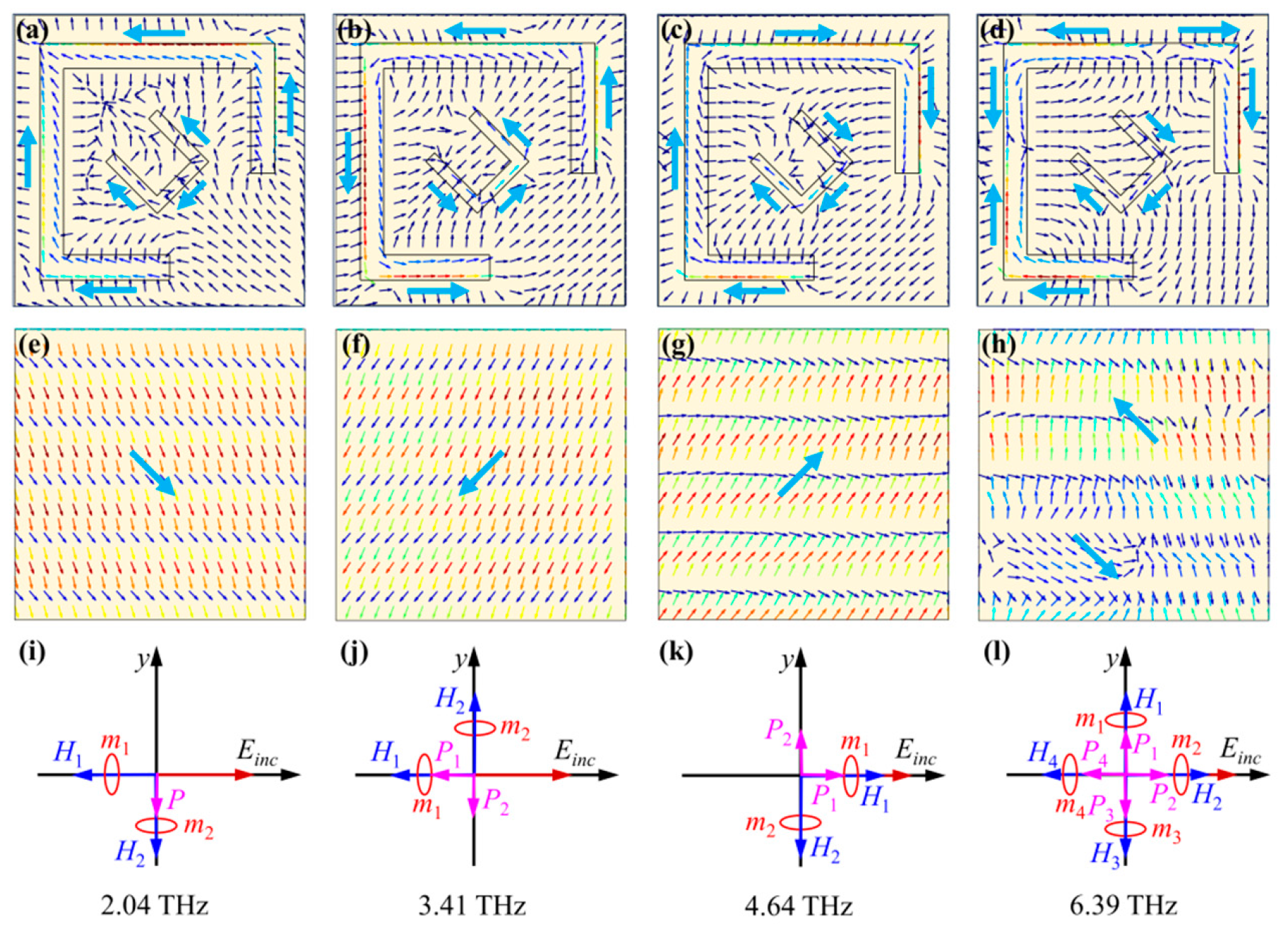
To better understand the physical mechanism of orthogonal linear-polarization conversion, the current distribution on the Au-VO2 composite layer and metal substrate was studied, as shown in Figure 12. At 2.04 THz, the current distribution on the Au-VO2 composite layer and metal substrate is shown in Figure 12a, e. According to the current flow direction on the upper and lower surfaces, a magnetic component H1 can be generated on the x-axis, and an electric resonance component P and a magnetic component H2 can be generated on the y-axis, as shown in Figure 12i. Among these, P is perpendicular to the direction of the incident electric field, which can generate an electric component perpendicular to the direction of the incident electric field. H1 is collinear with the direction of the electric field, which can generate cross-coupling. Therefore, P and H1 are the key to achieving orthogonal polarization conversion at 2.04 THz.
The current at 3.41 THz, 4.64 THz, and 6.39 THz can also be analyzed according to the above approach. At 3.41 THz and 4.64 THz, as shown in Figure 12j, k, the electric component P2 orthogonal to the x-axis and the magnetic component H1 collinear with the x-axis can generate an electric field perpendicular to the x-direction, achieving orthogonal linear-polarization conversion. At 6.39 THz, as shown in Figure 12l, the electric components P1 and P3 orthogonal to the x-axis, as well as the magnetic components H2 and H4 collinear with the x-axis, can generate an electric field perpendicular to the x-direction, achieving orthogonal linear polarization conversion.

3.4. Asymmetrical Transmission

When VO2 is in its insulating state and the chemical potential of graphene is 0 eV, the device exhibits the AT characteristics of circularly polarized waves. Electromagnetic waves whose electric field vector rotates counterclockwise or clockwise as the wave propagates are called left-handed circularly polarized waves (LHCP) and right-handed circularly polarized waves (RHCP), respectively. For LHCP, AT is the total transmission difference between forward and reverse LHCP incidence. Similarly, the AT of RHCP is the total transmission difference between forward and reverse RHCP incidence. Therefore, the AT of circularly polarized light can be expressed as [37]:
L H C P = T L H C P ( F ) T L H C P ( B )
R H C P = T R H C P ( F ) T R H C P ( B )
Here, Δ is the AT parameter, and F and B denote the forward (−z) and backward (+z) propagation of electromagnetic waves, respectively.
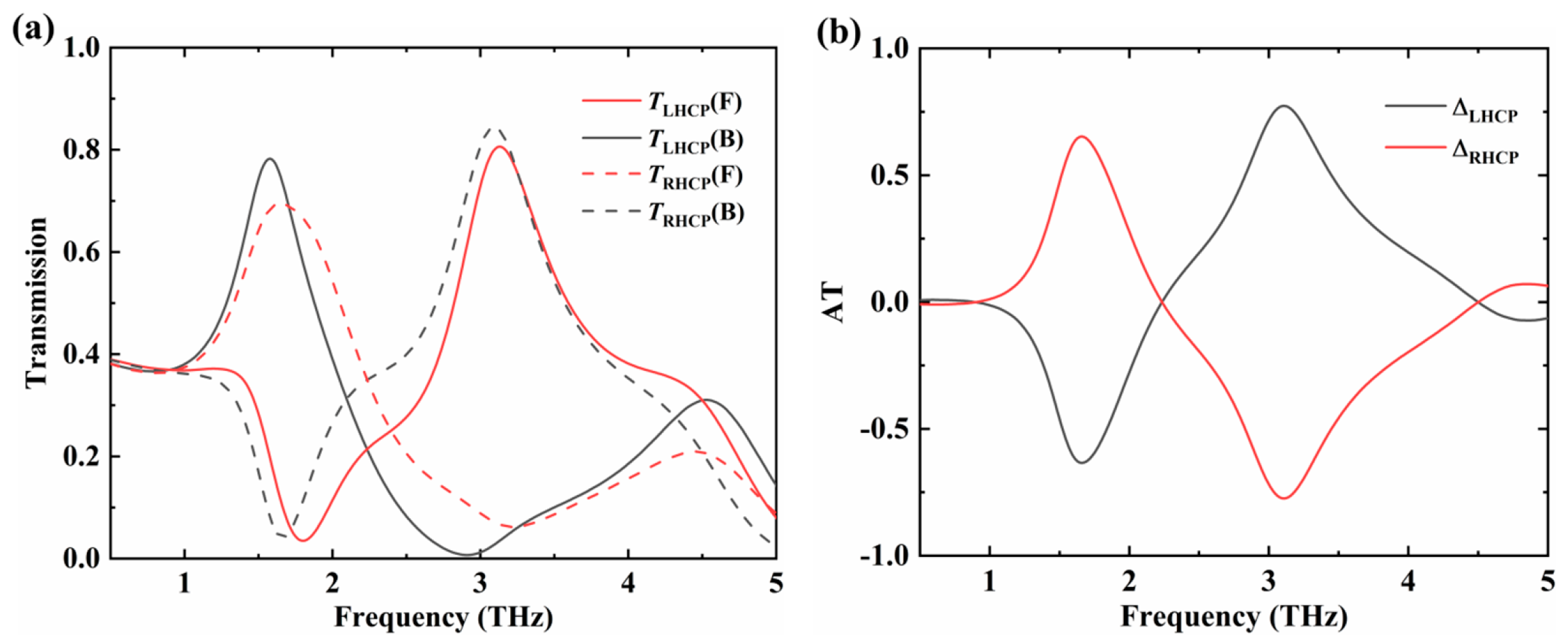
When VO2 transitions from a metallic state to an insulating state and the chemical potential of graphene is 0 eV, the inner split ring of the Au-VO2 composite structure is nearly inactive. The outer split rings in the upper and lower layers are symmetric at about 45° and appear anisotropic. They form a chiral metamaterial structure with the intermediate metal grating layer. Figure 13a shows the total transmittance of the device when LHCP and RHCP are incident in the forward and reverse directions, respectively. The transmission difference between LHCP and RHCP is obvious at 1.66 THz and 3.1 THz in both propagation directions. According to Equations (8) and (9), the asymmetric transmission values ΔLHCP and ΔRHCP reach −0.633, 0.774 and 0.653, −0.773, respectively, as shown in Figure 13b.
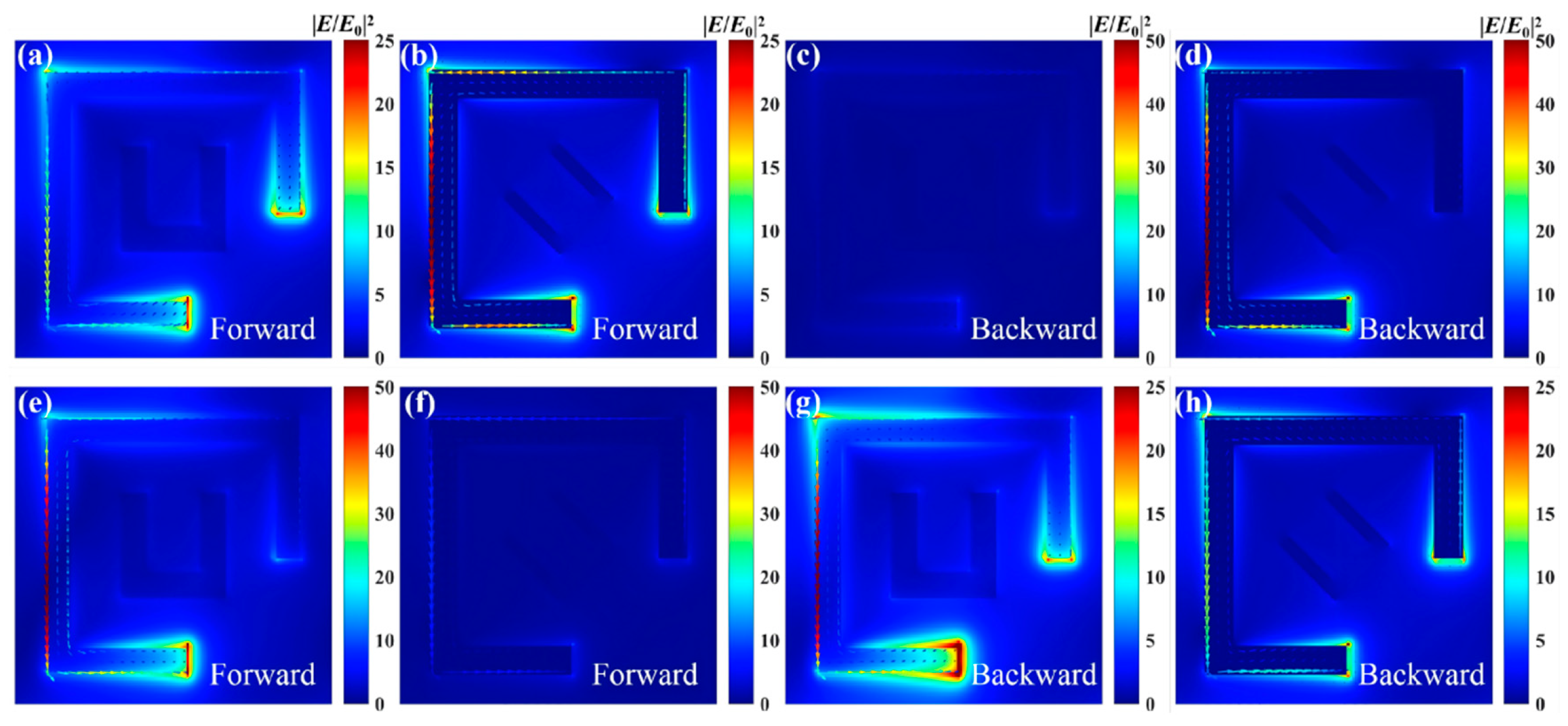
In order to further understand the AT mechanism of the device, Figure 14 shows the electric field intensity and current vector distributions of forward- and reverse-propagating LHCP and RHCP on the surface of the upper and lower Au-VO2 composite layers at 3.1 THz, where the transmission difference is most pronounced [44].
Figure 14a shows that, during forward transmission of LHCP, the electric field at the opening of the upper gold split ring is strongly excited and the electric dipole resonance is formed at the openings on both sides, exhibiting obvious local surface plasmon resonance characteristics. Electromagnetic waves are then emitted into the dielectric layer due to this strong resonance. As shown in Figure 14b, strong current and electric field distributions appear on the surface of the lower gold split ring, indicating that when the electromagnetic wave reaches the surface of the lower metal split ring, the electric field is further excited at the opening. After that, it is emitted into the dielectric layer and then propagates into the air, resulting in high transmittance. Figure 14d shows the electric field and current distributions on the surface of the lower gold split ring when the LHCP is transmitted in the reverse direction. Only the electric field at the lower opening is excited, while the electric field component at the right opening is almost zero. As a result, no electric dipole resonance is formed at the openings on both sides. Combined with Figure 14c, there is almost no current and electric field distribution on the surface of the upper gold split ring. Therefore, most of the reverse incident LHCP is reflected by the lower split ring, thus realizing the AT effect for LHCP. For the forward and reverse transmission of RHCP at 3.1 THz, the distributions of the electric field and current on the surfaces of the upper and lower gold split rings are like those for LHCP transmission, as shown in Figure 14e–h. The forward-transmitted RHCP is largely reflected by the upper gold split ring, while the reverse-transmitted RHCP forms an electric dipole resonance at the openings on both sides of the lower gold split ring. This resonance is transferred to the lower gold split ring, where it generates strong current and a strong electric field on its surface. It is then further excited and transmitted into the air, thus realizing the AT effect for RHCP.

4. Device Performance Comparison

Table 2 shows the research status of terahertz metamaterial devices based on tunable materials, which are related to broadband absorption, polarization modulation and other functions. The results show that although most devices can achieve multiple polarization conversion functions, these devices cannot guarantee a high relative bandwidth under each function. In contrast, the polarization converter proposed in this section has a relatively high relative bandwidth under various polarization conversion modes. The relative bandwidths under the four polarization conversion modes of LTL, LTC, RCTL and LCTL are 99.5%, 73.7%, 70.9%, and 75.6%, respectively, which is of great significance for switchable and tunable broadband terahertz polarization conversion and its related applications. The fractional bandwidth (FBW) is defined as the ratio of the signal bandwidth to the center frequency. The positive italics in the table are used to distinguish the implemented functions and the specific work efficiency. R and T in the brackets represent the reflection and transmission modes, respectively.

5. Conclusions

In this paper, a bidirectional multifunctional terahertz metamaterial device based on VO2 and graphene is proposed and studied. By controlling the phase transition state of VO2 and the chemical potential of graphene, a broadband absorption with a relative bandwidth of 101.1% and an absorption rate of more than 90% can be achieved in the terahertz band. Moreover, an orthogonal linear-polarization conversion with a relative bandwidth of 126.3% and a PCR of more than 90%, and asymmetric transmission with an AT value of 0.774, and a circular dichroism effect with a CD value of 0.69 were achieved.
The specific function is as follows: when VO2 is in its metal state and the chemical potential of graphene is 1 eV, the circularly polarized light is transmitted in the positive direction, and the device exhibits CD characteristics; planar light is transmitted in reverse, and the device is a broadband absorber. When VO2 is in its metal state and the chemical potential of graphene is 0 eV, the circularly polarized light is transmitted in a positive direction, and the device exhibits CD characteristics. Linearly polarized light is transmitted in reverse, and the device is characterized as a broadband orthogonal polarization converter. When the chemical potential of graphene is 0 eV and VO2 is in an insulating state, the device exhibits the AT effect of circularly polarized light. The multifunctional metamaterial device proposed in this paper has a good application prospect in the field of terahertz integrated devices because of its rich and adjustable functions. Future work will focus on the experimental realization of the proposed multilayer metasurface. Experimental characterization via terahertz time-domain spectroscopy will be carried out to verify the simulated performance when experimental infrastructures are accessible.

Author Contributions

Conceptualization, B.N. and G.H.; methodology, G.H.; software, B.N.; validation, X.H.; formal analysis, X.H.; investigation, X.H.; resources, B.N.; data curation, X.H.; writing—original draft preparation, X.H.; writing—review and editing, B.N.; visualization, G.H.; supervision, G.H.; project administration, G.H.; funding acquisition, G.H. All authors have read and agreed to the published version of the manuscript.

Funding

This research was funded by the National Natural Science Foundation of China (No. 12074192).

Institutional Review Board Statement

Not applicable.

Informed Consent Statement

Not applicable.

Data Availability Statement

All data that support the findings of the study have been included in the manuscript.

Conflicts of Interest

The authors declare no conflicts of interest.

References

  1. Zang, X.; Yao, B.; Chen, L.; Xie, J.; Guo, X.; Balakin, A.V.; Shkurinov, A.P.; Zhuang, S. Metasurfaces for manipulating terahertz waves. Light Adv. Manuf. 2021, 2, 148–172. [Google Scholar] [CrossRef] [Scilit]
  2. Wallace, V.P.; MacPherson, E.; Zeitler, J.A.; Reid, C. Three-dimensional imaging of optically opaque materials using nonionizing terahertz radiation. J. Opt. Soc. Am. A 2008, 25, 3120–3133. [Google Scholar] [CrossRef] [Scilit] [PubMed]
  3. Yu, N.F.; Genevet, P.; Kats, M.A.; Aieta, F.; Tetienne, J.P.; Capasso, F.; Gaburro, Z. Light propagation with phase discontinuities: Generalized laws of reflection and refraction. Science 2011, 334, 333–337. [Google Scholar] [CrossRef] [Scilit] [PubMed]
  4. Zha, Y.F.; Cheng, S.B. Tunable high-sensitivity mid-infrared perfect absorber with five resonance peaks based on nested circular and elliptical ring graphene surface plasmons. Phys. B Condens. Matter 2026, 739, 418929. [Google Scholar] [CrossRef] [Scilit]
  5. Wang, Y.T.; Cheng, S.B.; Li, B.X.; Tang, C.J.; Gao, F.; Yi, Y.G. Mid-Infrared High-Sensitivity Four-Peak Graphene Absorber Based on Circular Ring-Nested Ellipses: Polarization-Independent Characteristics and Dynamic Tunability. Phys. E Low-Dimens. Syst. Nanostruct. 2026, 181, 116523. [Google Scholar] [CrossRef] [Scilit]
  6. Huang, L.; Xu, L.; Powell, D.A.; Padilla, W.J.; Miroshnichenko, A.E. Resonant leaky modes in all-dielectric metasystems: Fundamentals and applications. Phys. Rep. 2023, 1008, 1–66. [Google Scholar] [CrossRef] [Scilit]
  7. Zhou, C.; Huang, L.; Jin, R.; Xu, L.; Li, G.; Rahmani, M.; Chen, X.; Lu, W.; Miroshnichenko, A.E. Bound states in the continuum in asymmetric dielectric metasurfaces. Laser Photonics Rev. 2023, 17, 2200564. [Google Scholar] [CrossRef] [Scilit]
  8. Huang, L.; Li, S.; Zhou, C.; Zhong, H.; You, S.; Li, L.; Cheng, Y.; Miroshnichenko, A.E. Realizing ultrahigh-Q resonances through harnessing symmetry-protected bound states in the continuum. Adv. Funct. Mater. 2024, 34, 2309982. [Google Scholar] [CrossRef] [Scilit]
  9. Zha, Y.F.; Shubo Cheng, S.B. TiN/SiO2 Multilayer Ultra-Broadband Solar Absorber with High-Temperature Stability and Multi-Resonance Synergy. Phys. Lett. A 2026, 590, 131859. [Google Scholar] [CrossRef] [Scilit]
  10. Li, Z.T.; Yi, Y.T.; Liu, M.S.; Yi, Y.G.; Tang, C.J.; Deng, J.; Li, B.X. Ultra-broadband solar absorber based on a Ti-SiO2-Ti multilayer structure with high efficiency and angular insensitivity. Opt. Commun. 2026, 616, 133369. [Google Scholar] [CrossRef] [Scilit]
  11. Yang, X.Y.; Guo, Y.; Cheng, S.S. Ultrabroadband Absorber Based on Titanium Nitride Concentric Dual-Ring Array for High-Efficiency Solar Energy Harvesting. Phys. B Condens. Matter 2026, 733, 418581. [Google Scholar] [CrossRef] [Scilit]
  12. Zhu, R.; Qiu, T.; Wang, J.; Sui, S.; Hao, C.; Liu, T.; Li, Y.; Feng, M.; Zhang, A.; Qiu, C.-W.; et al. Phase-to-pattern inverse design paradigm for fast realization of functional metasurfaces via transfer learning. Nat. Commun. 2021, 12, 2974. [Google Scholar] [CrossRef] [Scilit] [PubMed]
  13. Zhu, R.; Wang, J.; Qiu, T.; Han, Y.; Fu, X.; Shi, Y.; Liu, X.; Liu, T.; Zhang, Z.; Chu, Z.; et al. Remotely mind-controlled metasurface via brainwaves. eLight 2022, 2, 10. [Google Scholar] [CrossRef] [Scilit]
  14. Wang, D.X.; Xu, K.D.; Luo, S.Y.; Cui, Y.; Zhang, L.; Liao, Z.; Cui, J. Dual-band terahertz absorber based on square ring metamaterial structure. Opt. Express 2023, 31, 5940–5950. [Google Scholar] [CrossRef] [Scilit] [PubMed]
  15. Mao, X.R.; Li, H.Y.; Gao, W.; Liu, M.S.; Li, B.X. Terahertz absorber with high sensitivity in triple bands based on AlCuFe. Photonics Nanostruct. Fundam. Appl. 2026, 71, 101566. [Google Scholar] [CrossRef] [Scilit]
  16. Fu, S.M.; Yang, X.Y. A terahertz four-band high-sensitivity perfect absorber based on Dirac semimetal. Phys. Lett. A 2026, 587, 131760. [Google Scholar] [CrossRef] [Scilit]
  17. Chen, M.; Wang, Y.X.; Zhao, Z.R. Monolithic metamaterial-integrated graphene terahertz photodetector with wavelength and polarization selectivity. ACS Nano 2022, 16, 17263–17273. [Google Scholar] [CrossRef] [Scilit] [PubMed]
  18. Cui, T.J.; Qi, M.Q.; Wan, X.; Zhao, J.; Cheng, Q. Coding metamaterials, digital metamaterials and programmable metamaterials. Light Sci. Appl. 2014, 3, e218. [Google Scholar] [CrossRef] [Scilit]
  19. Sun, D.D.; Qi, L.M.; Liu, Z.Y. Terahertz broadband filter and electromagnetically induced transparency structure with complementary metasurface. Results Phys. 2020, 16, 102887. [Google Scholar] [CrossRef] [Scilit]
  20. Chen, S.Q.; Liu, W.W.; Li, Z.C.; Cheng, H.; Tian, J.G. Metasurface-Empowered Op-tical Multiplexing and Multifunction. Adv. Mater. 2020, 32, 1805912. [Google Scholar] [CrossRef] [Scilit] [PubMed]
  21. Liu, M.; Plum, E.; Li, H.; Li, S.; Xu, Q.; Zhang, X.; Zhang, C.; Zou, C.; Jin, B.; Han, J.; et al. Temperature-controlled optical activity and negative refractive index. Adv. Funct. Mater. 2021, 31, 2010249. [Google Scholar] [CrossRef] [Scilit]
  22. Liang, Z.; Wu, J.; Cui, Y.; Sun, H.; Ning, C.-Z. Self-optimized single-nanowire photoluminescence thermometry. Light Sci. Appl. 2023, 12, 36. [Google Scholar] [CrossRef] [Scilit] [PubMed]
  23. Li, Z.H.; Yang, R.C.; Wang, J.Y.; Zhao, Y.; Tian, J.; Zhang, W. Multifunctional metasurface for broadband absorption, linear and circular polarization conversions. Opt. Mater. Express 2021, 11, 3507–3519. [Google Scholar] [CrossRef] [Scilit]
  24. Qiu, Y.; Yan, D.X.; Feng, Q.Y.; Li, X.-J.; Zhang, L.; Qiu, G.-H.; Li, J.-N. Vanadium dioxide-assisted switchable multifunctional metamaterial structure. Opt. Express 2022, 30, 26544–26556. [Google Scholar] [CrossRef] [Scilit] [PubMed]
  25. Zhao, R.; Su, L.; Wang, T.; Cong, D.; Wang, S.; Gao, Y. Multifunctional metasurface for absorption and polarization conversion based on VO2 and graphene in terahertz band. Phys. Scr. 2025, 100, 085554. [Google Scholar] [CrossRef] [Scilit]
  26. Wang, Z.J.; Jia, H.; Yao, K.; Cai, W.; Chen, H.; Liu, Y. Circular dichroism metamirrors with near-perfect extinction. ACS Photonics 2016, 3, 2096–2101. [Google Scholar] [CrossRef] [Scilit]
  27. Singh, R.; Plum, E.; Menzel, C.; Rockstuhl, C.; Azad, A.K.; Cheville, R.A.; Lederer, F.; Zhang, W.; Zheludev, N.I. Terahertz metamaterial with asymmetric transmission. Phys. Rev. B 2009, 80, 153104. [Google Scholar] [CrossRef] [Scilit]
  28. Ren, Y.; Tang, B. Switchable multi-functional VO2-integrated metamaterial devices in the terahertz region. J. Light. Technol. 2021, 39, 5864–5868. [Google Scholar] [CrossRef] [Scilit]
  29. Qureshi, U.R.; Hu, B.; Khan, M.I.; Ahmad, M. Multifunctional active terahertz metasurface with electromagnetically induced transparency, perfect absorption, and circular dichroism. Opt. Commun. 2024, 550, 129989. [Google Scholar] [CrossRef] [Scilit]
  30. Wu, Z.Y.; Hou, C.J.; Meng, Z.K.; Han, B.Y.; Li, X.H. VO2-based multifunctional switchable polarization conversion metasurface. Phys. Scr. 2025, 100, 085571. [Google Scholar] [CrossRef] [Scilit]
  31. Cao, T.N.; Nguyen, M.T.; Nguyen, N.H.; Truong, C.L.; Nguyen, T.Q.H. Numerical design of a high efficiency and ultra-broadband terahertz cross-polarization converter. Mater. Res. Express 2021, 8, 065801. [Google Scholar] [CrossRef] [Scilit]
  32. Chen, P.Y.; Alù, A. Atomically thin surface cloak using graphene monolayers. ACS Nano 2011, 5, 5855–5863. [Google Scholar] [CrossRef] [Scilit] [PubMed]
  33. Chen, P.Y.; Alù, A. Terahertz metamaterial devices based on graphene nanostructures. IEEE Trans. Terahertz Sci. Technol. 2013, 3, 748–756. [Google Scholar] [CrossRef] [Scilit]
  34. Huang, J.; Li, J.N.; Yang, Y.; Li, J.; Li, J.; Zhang, Y.; Yao, J. Active controllable dual broadband terahertz absorber based on hybrid metamaterials with vanadium dioxide. Opt. Express 2020, 28, 7018–7027. [Google Scholar] [CrossRef] [Scilit] [PubMed]
  35. Wu, G.Z.; Jiao, X.F.; Wang, Y.D.; Zhao, Z.; Wang, Y.; Liu, J. Ultra-wideband tunable metamaterial perfect absorber based on vanadium dioxide. Opt. Express 2021, 29, 2703–2711. [Google Scholar] [CrossRef] [Scilit] [PubMed]
  36. Liu, Y.X.; Gu, M.N.; Tian, Y.; Liu, J.; Zhu, M.M.; Zhou, H.M.; Li, C.X.; Fang, B.; Hong, Z.; Jing, X.F. 3D Printed Metamaterial Absorber Based on Vanadium Dioxide Phase Transition Control Prepared at Room Temperature. Laser Photonics Rev. 2025, 19, 2401673. [Google Scholar] [CrossRef] [Scilit]
  37. Ren, Y.; Zhou, T.L.; Jiang, C.; Tang, B. Thermally switching between perfect absorber and asymmetric transmission in vanadium dioxide-assisted metamaterials. Opt. Express 2021, 29, 7666–7679. [Google Scholar] [CrossRef] [Scilit] [PubMed]
  38. Wu, R.L.; Li, J.S. Terahertz metasurfaces with both linearly polarized and circularly polarized wave absorption. Acta Phys. Sin. 2023, 72, 057802. [Google Scholar] [CrossRef] [Scilit]
  39. Smith, D.R.; Schultz, S.; Markos, P.; Soukoulis, C.M. Determination of effective permittivity and permeability of metamaterials from reflection and transmission coefficients. Phys. Rev. B 2001, 65, 195104. [Google Scholar] [CrossRef] [Scilit]
  40. Bao, Z.Y.; Tang, Y.; Hu, Z.D.; Zhang, C.; Balmakou, A.; Khakhomov, S.; Semchenko, I.; Wang, J. Inversion method characterization of graphene-based coordination absorbers incorporating periodically patterned metal ring metasurfaces. Nanomaterials 2020, 10, 1102. [Google Scholar] [CrossRef] [Scilit] [PubMed]
  41. Zhang, S.Z.; Qi, Y.P.; Zhou, Z.H.; Shi, Q.; Wang, L.; Luo, B. Versatile terahertz metasurface: Dynamic switching between electromagnetically induced transparency and perfect absorption. J. Opt. Soc. Am. B 2024, 41, 863–872. [Google Scholar] [CrossRef] [Scilit]
  42. Ako, R.T.; Lee, W.S.L.; Bhaskaran, M.; Sriram, S.; Withayachumnankul, W. Broadband and wide-angle reflective linear polarization converter for terahertz waves. APL Photonics 2019, 4, 096104. [Google Scholar] [CrossRef] [Scilit]
  43. Slovick, B.A.; Yu, Z.G.; Krishnamurthy, S. Generalized effective-medium theory for metamaterials. Phys. Rev. B 2014, 89, 155118. [Google Scholar] [CrossRef] [Scilit]
  44. Cheng, Y.Z.; Fan, J.P.; Luo, H.; Chen, F.; Feng, N.; Mao, X.; Gong, R. Dual-band and high-efficiency circular polarization conversion via asymmetric transmission with anisotropic metamaterial in the terahertz region. Opt. Mater. Express 2019, 9, 1365–1376. [Google Scholar] [CrossRef] [Scilit]
  45. Zhang, H.; He, X.C.; Zhang, D.; Zhang, H. Multitasking device with switchable and tailored functions of ultra-broadband absorption and polarization conversion. Opt. Express 2022, 30, 23341–23358. [Google Scholar] [CrossRef] [Scilit] [PubMed]
  46. Zhao, Y.J.; Yang, R.C.; Wang, Y.X.; Zhang, W.; Tian, J. VO2-assisted multifunctional metamaterial for polarization conversion and asymmetric transmission. Opt. Express 2022, 30, 27407–27417. [Google Scholar] [CrossRef] [Scilit] [PubMed]
  47. Yin, Z.F.; Tian, Y.; Yang, S.Q.; Zhang, X.; Guo, L.; Kong, W.; Zhang, K. Broadband terahertz metasurface with three switchable functions based on complementary structure. Diam. Relat. Mater. 2023, 140, 110449. [Google Scholar] [CrossRef] [Scilit]
  48. Wang, J.Y.; Niu, Y.Y.; Kang, J.F.; Qu, Z.; Duan, J.; Zhang, B. Multipath-controlled bidirectional metasurface for multitasking polarization regulation and absorption. Opt. Express 2024, 32, 6391–6408. [Google Scholar] [CrossRef] [Scilit] [PubMed]
  49. Long, Z.; Xu, Z. Multifunctional metasurface based on vanadium dioxide in the terahertz frequency. Appl. Opt. 2025, 64, 4692–4700. [Google Scholar] [CrossRef] [Scilit] [PubMed]
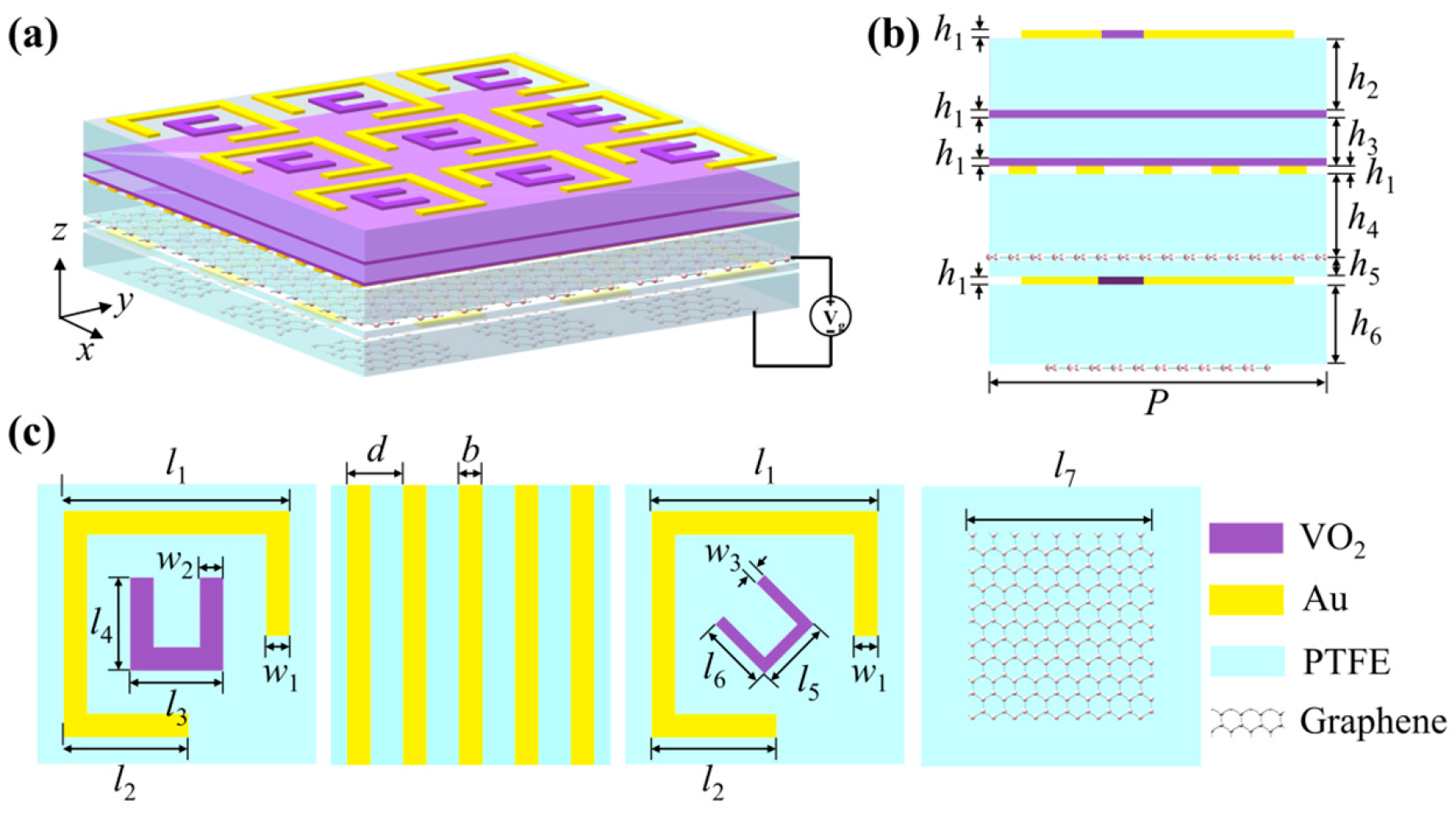
Figure 1. Overall view of multifunctional metamaterial structure. (a) Three-dimensional view; (b) side view; (c) top view of each layer.
Photonics 13 00852 g001
Figure 2. Fabrication process of the proposed multifunctional metasurface.
Photonics 13 00852 g002
Figure 3. The function of the device when the forward and reverse electromagnetic waves are incident while graphene and VO2 are in different states.
Photonics 13 00852 g003
Figure 4. LCP and RCP forward transmission under (a) absorption spectrum (b) CD value.
Photonics 13 00852 g004
Figure 5. Surface current and electric field distribution of the top Au-VO2 composite layer under forward propagation of different circularly polarized waves: (a) LCP, (b) RCP.
Photonics 13 00852 g005
Figure 6. Broadband absorption, (a) absorption rate, (b) equivalent impedance. The absorption rate of 90% is marked with a dotted line in the figure.
Photonics 13 00852 g006
Figure 7. The effect of structure composition on absorption when the device is a broadband absorber: (a) graphene layer, (b) Au-VO2 composite structure.
Photonics 13 00852 g007
Figure 8. The change of absorption rate under the change of graphene chemical potential when the device is a broadband absorber.
Photonics 13 00852 g008
Figure 9. The absorptivity: (a) 0–45°, (b) 90–135° at different polarization angles when the device is a broadband absorber.
Photonics 13 00852 g009
Figure 10. Polarization conversion rate of (a) reflection amplitude Rxx/RLL and Ryx/RRL, and (b) under the incidence of an x-polarized wave/left-circularly polarized wave. The 90% polarization conversion rate is marked by a dotted line in the figure.
Photonics 13 00852 g010
Figure 11. Reflection wave distribution along the u and v directions under orthogonal linear-polarization conversion. (a) Reflection amplitude Ru and Rv. (b) Phase distribution.
Photonics 13 00852 g011
Figure 12. Under orthogonal linear-polarization conversion: (a,e,i) 2.04 THz, (b,f,j) 3.41 THz, (c,g,k) 4.64 THz, and (d,h,l) 6.39 THz. Au-VO2 surface, metal substrate surface current distribution, equivalent electric moment and magnetic moment. Blue arrows mark the current flow direction in the outer split ring (Au), inner split ring (VO2), and metal substrate.
Photonics 13 00852 g012
Figure 13. Forward and backward transmission of left-handed circularly polarized light and right-handed circularly polarized light: (a) transmittance, (b) AT value.
Photonics 13 00852 g013
Figure 14. Current and electric field distribution on the surface of the Au-VO2 composite layer: (a,b) left-handed circularly polarized light forward transmission; (c,d) left-handed circularly polarized light backward transmission; (e,f) right-handed circularly polarized light forward transmission; (g,h) right-handed circularly polarized light backward transmission.
Photonics 13 00852 g014
Table 1. Structural parameters of multifunctional metamaterials.
ParameterValue (μm)ParameterValue (μm)ParameterValue (μm)ParameterValue (μm)
h10.5h29h35h410
h51h610l119.4l210.7
l38l48l56l66
l716w12w22w31
b2d4.8P24
Table 2. Performance comparison of terahertz multifunctional devices.
Refs.Adjustable MaterialsRealizing FunctionWorking Range (THz)Operating EfficiencyFBW
[45]Photosensitive silicon VO2A
LTL (R)
0.68–1.6
0.82–1.6
A > 0.9
PCR > 0.9
80%
64%
[46]VO2A
AT
0.61–1.63
0.64
A > 0.9
AT = 0.7
91.1%
/
[47]Graphene
VO2
A
LTL
LTC
0.63–1.32
0.64–1.37
0.65–1.27
A > 0.9
PCR > 0.9
|η| > 0.9
70.8%
72.6%
70.8%
[48]Graphene
VO2
A
LTL (R)
LTL (T)
LTC (R)
total reflection
0.54–1.18
0.45–1.1
0.48–0.58/0.56–0.75
0.42/1.21/1.61
0.1–2
A > 0.9
PCR > 0.9
PCR > 0.8
|η| » 1
R > 0.9
74.4%
83.9%
18.9%/29%
/
181%
[29]VO2A
CD
EIT
1.1
1.1
1.291–1.749
A > 0.98
CD = 0.42
/
/
/
30.1%
[49]VO2VBG
A
LTC
1.0
1.55/2.95
0.5–0.9/1.2–1.5
/
A > 0.98
|η| > 0.9
/
/
57.1%/22.2%
In this workGraphene
VO2
A
LTL (R)
AT
CD
2.68–8.16
1.6–7.08
1.66/3.1
5.65
A > 0.9
PCR > 0.9
AT = 0.653/0.774
CD = 0.69
101.1%
126.3%
/
/
Disclaimer/Publisher’s Note: The statements, opinions and data contained in all publications are solely those of the individual author(s) and contributor(s) and not of MDPI and/or the editor(s). MDPI and/or the editor(s) disclaim responsibility for any injury to people or property resulting from any ideas, methods, instructions or products referred to in the content.