Article

Narrow-Linewidth and High Side-Mode-Suppression-Ratio 1064 nm Distributed Feedback Semiconductor Laser Enabled by Fiber Bragg Grating External Feedback


Department of Physics, Capital Normal University, Beijing 100048, China
*
Author to whom correspondence should be addressed.
Photonics 2026, 13(7), 677; https://doi.org/10.3390/photonics13070677
Submission received: 14 June 2026 / Revised: 5 July 2026 / Accepted: 14 July 2026 / Published: 15 July 2026
(This article belongs to the Special Issue Advanced Lasers and Their Applications, 3rd Edition)

Abstract

To narrow spectral linewidth, stabilize longitudinal mode and improve output performance of a 1064 nm distributed feedback (DFB) semiconductor laser, we design and fabricate a laser module adopting fiber Bragg grating (FBG) external-cavity feedback and a butterfly packaging structure. The butterfly package effectively enhances heat dissipation and optical coupling reliability. Based on the classic Schawlow–Townes theory, we elaborate on how the narrowband filtering of FBG and the extended external cavity suppress mode hopping and reduce laser linewidth. A delayed self-heterodyne testing system is built to evaluate the photoelectric characteristics, spectral features and linewidth performance under varying driving currents and ambient temperatures. Experimental results show that the laser has a threshold current of 22.54 mA and a slope efficiency of 0.18 W/A, and its maximum output power reaches 80.8 mW at 480 mA. The side-mode suppression ratio (SMSR) reaches 58.2 dB at a temperature of 25 °C and driving current of 150 mA. Benefiting from FBG feedback, the laser linewidth is compressed from 485 kHz to 115 kHz, with lower noise and excellent wavelength stability. This compact all-fiber laser is well-suited for fiber sensing, coherent detection and LiDAR systems.

1. Introduction

Narrow-linewidth lasers at 1064 nm [1] are core components in laser technology and widely used as seed lasers for all-solid-state lasers and fiber lasers, as well as in coherent detection, nonlinear frequency conversion, precision measurement and LIDAR [2]. The narrow-linewidth characteristic determines the coherence of the whole laser system, further affects detection accuracy and frequency stability, and serves as the crucial technical support for practical applications in relevant research fields.
Compared with thin-disk oscillators, bulk solid-state lasers, and fiber lasers, the proposed DFB–FBG laser offers distinct advantages in compactness, system integration, and alignment-free operation. Unlike thin-disk [3] and bulk solid-state lasers [4] that rely on free-space cavities, the all-fiber FBG external cavity does not require additional optical alignment and it provides wavelength-selective optical feedback, which contributes to stable single-frequency operation and can suppress phase noise under appropriate feedback conditions. Compared with fiber lasers [5,6], the DFB–FBG laser features a much smaller cavity and supports direct electrical modulation while maintaining a narrow linewidth and high wavelength stability. Although its output power is lower than that of high-power laser systems, these characteristics make it particularly suitable for compact seed sources in coherent communications, precision sensing, coherent beam combining, and fiber amplifier systems.
Overall, the proposed 1064 nm DFB-FBG laser provides a favorable balance among linewidth, side-mode suppression ratio, output power, compactness, and fabrication simplicity, making it a promising candidate for practical applications [7].
As shown in Table 1, through the combined wavelength-selective effects of the DFB grating and the FBG external cavity, the fabricated laser achieves a narrowed linewidth together with a high side-mode suppression ratio (SMSR). Compared with linewidth-narrowing approaches relying on complex surface microstructures or photonic crystal fabrication, the proposed FBG external-feedback scheme adopts a simpler device configuration, thereby reducing fabrication complexity, simplifying the fabrication process and potentially reducing fabrication cost. Moreover, the optical fiber simultaneously serves as both the feedback path and the output waveguide, avoiding the additional coupling losses associated with separately constructed external cavities and helping maintain a relatively high output power. Consequently, the proposed device provides a favorable combination of narrow linewidth, high SMSR, and relatively high output power, making it attractive for practical engineering applications.
At present, the distributed feedback (DFB) cavity is the dominant structure for single-frequency 1064 nm lasers. Restricted by the short inherent cavity length of commercial 1064 nm DFB laser diodes, the typical linewidth of conventional DFB semiconductor lasers is on the order of several megahertz, leaving considerable room for linewidth reduction. According to the laser linewidth formula, a longer resonant cavity yields a narrower spectral linewidth. Provided that the bandwidth of the filter or gain medium is narrow enough to guarantee single-longitudinal-mode operation, extending the equivalent cavity length enables the fabrication of single-frequency narrow-linewidth 1064 nm lasers. Although lasers integrated with silicon nitride-based external cavities [17] can greatly narrow laser linewidth, their insufficient output power restricts their practical applicability for many scenarios. By contrast, enhanced fiber Bragg grating (FBG) external-cavity feedback can lower laser threshold and reduce spectral linewidth while maintaining relatively high output power. Within a certain range, extending external-cavity length contributes to effective linewidth compression. In accordance with the Schawlow–Townes linewidth formula [18], laser linewidth is inversely proportional to equivalent cavity length; accordingly, a longer cavity corresponds to a narrower linewidth. Moreover, lasers with conventional packaging suffer from deteriorated frequency noise and modal stability caused by stray reflection, variable coupling conditions and thermal effects. In comparison, butterfly packaging [19] possesses superior structural stability, high coupling efficiency and excellent heat dissipation performance, which is commonly adopted for DFB lasers and long-haul optical communication devices.To date, published studies concerning narrow-linewidth lasers at 1064 nm are far fewer than those for 1310 nm and 1550 nm bands, and limited works focus on DFB lasers with external FBG feedback.
In this work, a 1064 nm DFB semiconductor laser module is designed and packaged via butterfly packaging. The fiber Bragg grating is adopted as both an output and feedback element to realize significant linewidth narrowing. The output spectra under various driving currents and P-I-V characteristics are measured experimentally, and quantitative linewidth evaluation is carried out with the delayed self-heterodyne method [20]. The fabricated device achieves a maximum output power of 80.8 mW, a side-mode suppression ratio (SMSR) exceeding 58.2 dB, and a linewidth of 115 kHz.

2. Device Structure and Design Principle

2.1. Structure of Chip and Packaging

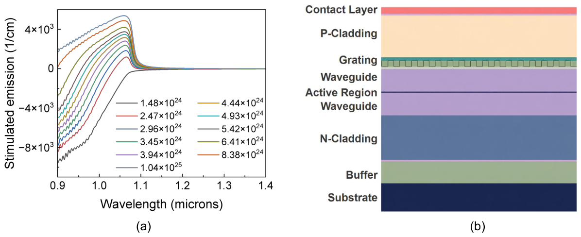
A strained quantum well structure is commonly adopted as the active region for 1064 nm DFB lasers. The waveguide is designed as a buried heterostructure, and the embedded active region is fabricated via a two-step epitaxial growth process. For the DFB laser developed in this work, InGaP is selected as the grating layer material for the integrated Bragg grating. Periodic corrugations are etched on the InGaP layer to form periodic modulation of refractive index and realize the grating function. An anti-reflection (AR) coating with designed reflectivity of 1–3% is deposited on the front facet of the laser chip, while a high-reflection (HR) coating with reflectivity exceeding 95% is coated on the rear facet. The laser chip is based on the InGaAs/GaAs material system. Precise bandgap tuning is achieved by regulating indium composition to center the material gain spectrum at 1064 nm, as illustrated in Figure 1a. The finalized epitaxial layer configuration is shown in Figure 1b.
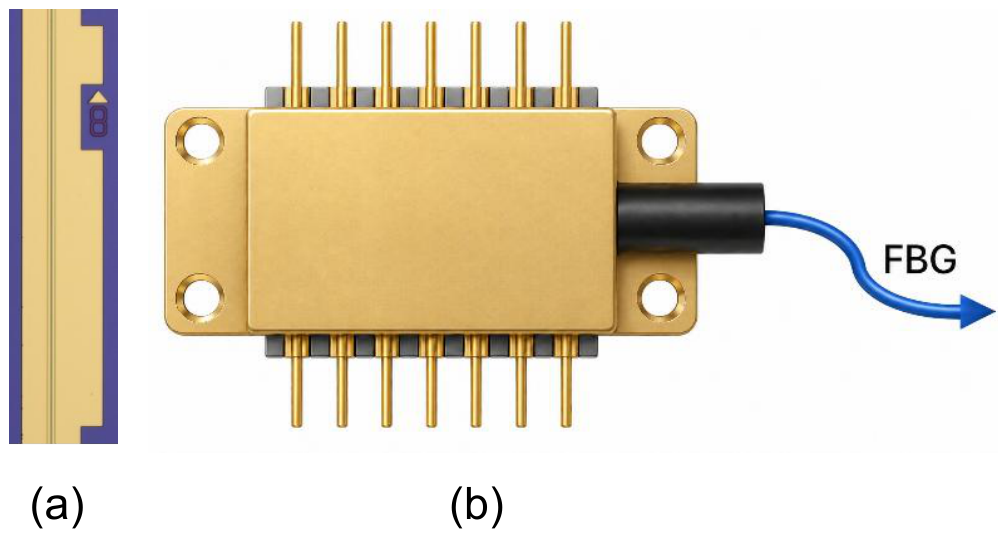
Owing to the Bragg condition of the DFB grating, only light with a specific wavelength can be fed back, realizing an excellent side-mode suppression ratio (SMSR). The bare chip itself possesses fundamental mode-selection capability, and the fabricated chip is shown in Figure 2a. After laser emission from the chip, a fiber Bragg grating is introduced to further improve frequency selectivity and compress spectral linewidth, and the schematic of the packaged module is given in Figure 2b.

2.2. Mechanism of Linewidth Narrowing Based on Fiber Bragg Grating Feedback

Fiber Bragg gratings feature an extremely narrow reflection bandwidth, and the maximum reflectivity is achieved only when the incident wavelength satisfies the Bragg condition. The Bragg wavelength of fiber grating is defined as λ = 2 n e f f Λ , where n e f f denotes the effective refractive index of fiber at the Bragg wavelength, and Λ is the grating period. The fiber Bragg grating realizes external-cavity mode selection by modulating the loss difference among different longitudinal modes. Benefiting from the narrow reflection spectrum of fiber grating, optical reflection occurs merely around the Bragg wavelength, delivering preferential optical feedback to the targeted mode. Consequently, modes deviating from the Bragg wavelength suffer drastically increased loss and are effectively suppressed.
The effective reflectivity at the external-cavity facet of the laser is wavelength-dependent, which further results in wavelength-sensitive resonant cavity loss. The resonant cavity mode satisfies m · λ 2 = n ¯ L , in which m stands for mode order, n ¯ is the effective refractive index, and L represents cavity length. The longitudinal mode closest to the gain peak with the minimum resonant cavity loss is defined as the dominant mode. From the formula Δ λ = λ 2 2 n ¯ L , the mode spacing Δ λ of the fiber-grating external-cavity semiconductor laser can be expressed as
Δ λ = λ 2 / 2 n 1 L CHIP + 2 n 2 L FBG
where L CHIP denotes the cavity length of the laser chip, L FBG is the external cavity length, and n 1 and n 2 represent the effective refractive indices of the laser chip and fiber Bragg grating respectively. Benefiting from the introduction of fiber Bragg grating, the mode spacing of external-cavity modes becomes smaller than the intrinsic longitudinal-mode spacing of the laser without external feedback. The reduced external-cavity mode spacing, together with the narrow reflection bandwidth of the FBG, modifies the modal loss distribution and enhances wavelength-selective feedback, thereby favoring single-longitudinal-mode operation.
Meanwhile, external feedback from FBG constructs an equivalent extended external cavity, which greatly increases the overall cavity length and photon lifetime. It suppresses the influence of phase fluctuation on instantaneous frequency and substantially narrows the laser emission linewidth.
In addition, the interference between the feedback optical field and intracavity optical field generates a standing-wave field, which counteracts spontaneous emission noise via self-injection locking. Part of the output light from the DFB laser is reflected by the FBG and recoupled back into the laser active region. When the reflected feedback light is phase-matched with the intracavity field, it participates in stimulated emission and provides a stable phase reference for the laser. Instantaneous fluctuations of laser frequency are restrained by the external-feedback field, reducing the phase diffusion rate. Optical reflection prolongs the photon lifetime of the target dominant mode and decreases its threshold gain, enabling the dominant mode to gain absolute predominance. Appropriate optical feedback can reduce the spectral density of frequency noise, improve the stability of the main mode and lower the probability of mode hopping. Laser linewidth is dominated by quantum phase noise originating from spontaneous emission, and the conventional Schawlow–Townes linewidth formula is expressed as [18]
Δ ν ST = h ν 0 α total 2 4 π P out
where h is Planck’s constant, ν 0 stands for the central frequency, α total is the total intracavity loss, and P out represents the output power. The laser linewidth is proportional to the square of cavity loss and inversely proportional to the intracavity photon lifetime as well as the intracavity photon number. Random perturbation of the optical field phase induced by spontaneous emission results in Lorentzian spectral broadening; meanwhile, multi-longitudinal-mode competition and mode hopping further degrade linewidth and frequency stability.
In accordance with the Schawlow–Townes equation, laser linewidth is associated with intracavity photon quantity, cavity loss and phase noise. External narrowband feedback improves mode selectivity and modifies the phase condition of complex amplitude. The external FBG constructs a composite resonant system to adjust the round-trip phase condition inside the cavity and produce a phase-locking effect. Moderate optical feedback suppresses the spectral density of frequency noise, equivalently extends photon lifetime and increases the effective intracavity photon population, which results in linewidths significantly narrower than those of the free-running DFB laser. The FBG reduces the equivalent total cavity loss and raises the quality factor Q of the resonant cavity. Combined with the long external-cavity configuration, it reduces longitudinal-mode spacing, further restrains phase fluctuation and frequency drift, and finally achieves linewidth reduction by orders of magnitude.

3. Experimental Methods and Results

3.1. Delayed Self-Heterodyne Method

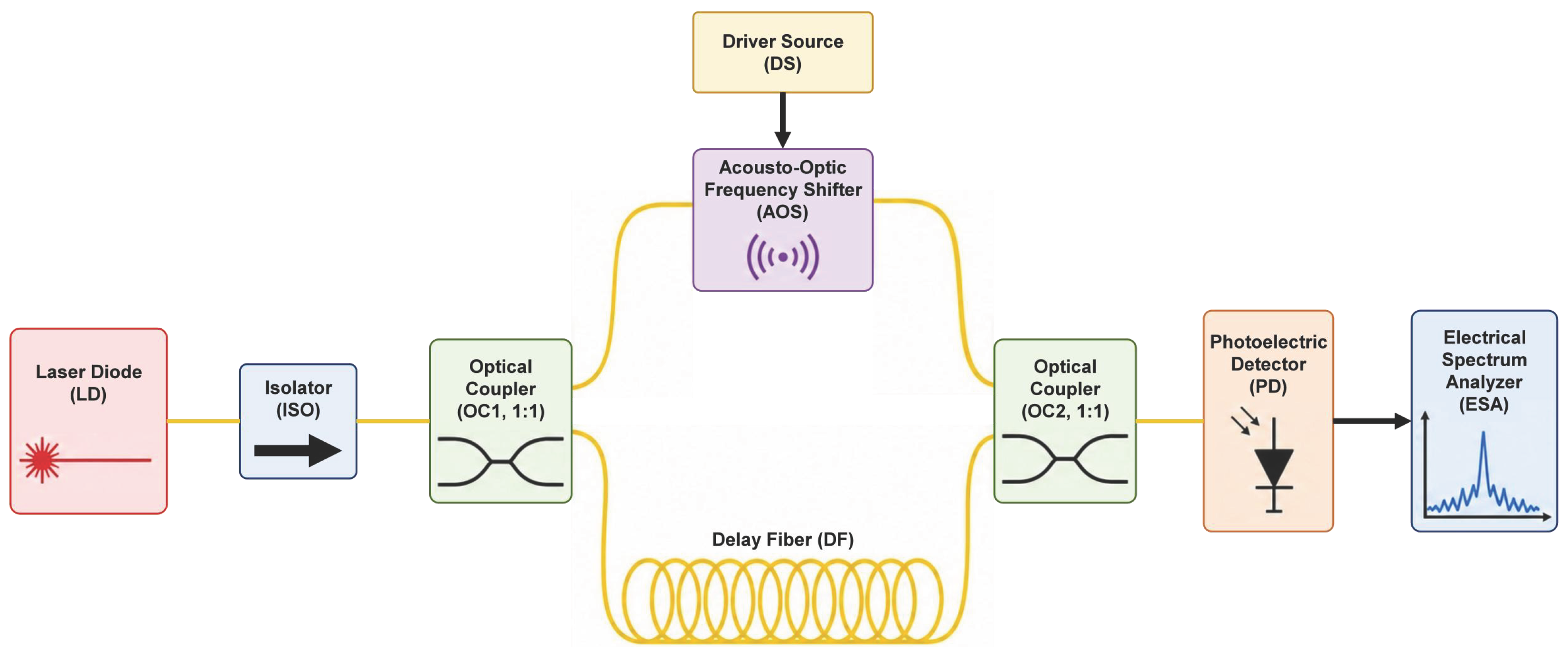
The measurement system based on the delayed self-heterodyne method [21] consists of a beam splitter, long delay optical fiber, acousto-optic modulator (AOM), optical coupler, photodetector and electrical spectrum analyzer. Figure 3 illustrates the test configuration adopted for characterizing the 1064 nm DFB laser.
The fundamental principle of the fiber-delayed self-heterodyne technique originates from an all-fiber Mach–Zehnder interferometer. An unequal-arm layout is adopted to construct the measurement setup, which converts laser frequency noise into intensity noise. The output beam from the DFB laser is split into two branches by an optical isolator and fiber beam splitter. One path serves as the signal light coupled into an optical fiber delay line, while the other acts as the reference light passing through an acousto-optic frequency shifter. Afterwards, the reference light interferes with the delayed signal light inside a fiber combiner to generate a beat-frequency signal, which is converted into an electrical signal via a photodetector. The corresponding power spectrum is displayed on a frequency spectrum analyzer to calculate the linewidth of the DFB laser. For reliable linewidth measurement using the delayed self-heterodyne method, the fiber delay time needs to exceed the coherence time of the tested laser. Normally the delay time is set to more than six times the laser coherence time to satisfy the approximate decorrelation condition and guarantee stable operation of the measurement system.
Ideally, a single-longitudinal-mode laser behaves as a quasi-monochromatic electromagnetic field with stable amplitude and stochastic phase perturbation, expressed as
E ( t ) = E 0 exp j ω 0 t + φ ( t )
where E 0 denotes the optical field amplitude, ω 0 is the central angular frequency of the electromagnetic field, and φ ( t ) represents random fluctuation of the optical phase responsible for spectral line broadening. The composite field intensity is characterized by the fiber-delayed self-heterodyne method [22], which is written as
E r ( t ) = E ( t ) + a E ( t + τ 0 )
where a is the amplitude splitting ratio of the two optical beams, τ 0 stands for the delay time introduced by the fiber delay line, and the subscript r represents the distance from the charge to the observation point. Benefiting from the square-law response characteristic of photodetectors, the resultant intensity noise is transformed from random phase fluctuations, and such variation manifests itself as spectral broadening of the photocurrent. Herein, the photocurrent autocorrelation function R 1 ( τ ) is introduced to correlate the linewidth of a single-longitudinal-mode laser with the photocurrent spectrum. The photocurrent autocorrelation function is determined by the intensity correlation function of the total composite optical field described in Equation (4), which is expressed as
R 1 ( τ ) = e σ G E T ( 2 ) ( 0 ) δ ( τ ) + σ 2 G E T ( 2 ) ( τ )
where e denotes the elementary electron charge, σ is the responsivity of the photodetector, δ stands for the Dirac delta function, G E T ( 2 ) ( τ ) represents the first-order photocurrent intensity function, the superscript ( 2 ) refers to the second-order derivative of the primitive function, E T is the electric field intensity, and the subscript T corresponds to magnetic flux density. The correlation function of this parameter is defined as
G E T ( 2 ) ( τ ) = E T ( t ) E T * ( t ) E T ( t + τ ) E T * ( t + τ )
According to the well-known Wiener–Khintchine theorem, the Fourier transform is performed on the photocurrent autocorrelation function. Substituting the transformed result into Equation (6) and adopting the same simplification as mentioned above yields
S 1 ( ω ) σ 2 E 0 4 = 1 + a 2 2 δ ( ω ¯ ) + a 2 exp τ ¯ 0 δ ( ω ¯ Ω ¯ ) + a 2 exp τ ¯ 0 π 1 + ω ¯ Ω ¯ 2 { exp ( τ ¯ 0 ) sin ω ¯ Ω ¯ τ ¯ 0 ω ¯ Ω ¯ cos ω ¯ Ω ¯ τ ¯ 0 }
In the formula, Ω denotes the fixed frequency shift introduced by the acousto-optic frequency shifter, Ω ¯ represents the frequency offset deviation of the acousto-optic frequency shifter, and a is the amplitude splitting ratio between the two optical beams. Half of the full width at half maximum (FWHM) extracted from the photocurrent power spectral density curve equals the measured laser linewidth. Accordingly, the actual laser linewidth can be experimentally determined by acquiring the FWHM of the beat-note spectrum in this work [23].
The laser linewidth was characterized using the delayed self-heterodyne method. A spool of 20 km single-mode fiber was employed as the delay arm, corresponding to a delay time of approximately 98 μs. Considering the measured linewidth of 115 kHz, the corresponding coherence time is
τ c = 1 π Δ v 2.77 μ s
Therefore, the delay time is approximately 35 times larger than the coherence time, ensuring that the optical fields in the two interferometer arms are effectively decorrelated. Under this condition, the measured 3 dB beat-note linewidth is approximately twice the laser linewidth, and the laser linewidth is obtained by dividing the measured 3 dB bandwidth by two.

3.2. Basic Optoelectronic Characteristics

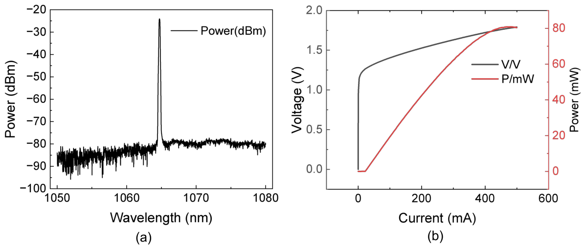
Figure 4 summarizes the basic optoelectronic characteristics of the fabricated device. As shown in Figure 4a, the laser operates at a center wavelength of 1064.74 nm. The measured PIV characteristics are presented in Figure 4b. It can be seen that the PIV curve is smooth and has no kinks, suggesting that no significant mode hopping occurs within the measured operating range.
As illustrated in Figure 4b, the output power P is nearly zero with only faint spontaneous emission when the injection current is below 22.54 mA. Once the current exceeds 22.54 mA, the P-I curve increases linearly accompanied by the onset of stimulated emission without additional nonlinear inflection points, which is a typical feature of single-mode lasing for DFB lasers. The measured threshold current of the fabricated device is 22.54 mA. The output power increases with the injection current and begins to saturate at approximately 480 mA, reaching a maximum value of 80.8 mW. According to the formula η s = Δ P / Δ I , the slope efficiency before saturation is calculated to be 0.18 W/A, demonstrating high optoelectronic conversion efficiency and low loss. The operating voltage characterizes the forward electrical property of the device. The forward voltage is 1.25 V at the threshold current of 22.54 mA and increases to 1.78 V at the maximum test current of 500 mA; hence, the normal operating voltage range of the device is 1.25–1.78 V. When the injection current is less than 5 mA, the voltage rapidly rises to 1.00 V, conforming to the forward V-I characteristic of PN junction conduction. With a low threshold current of 22.54 mA, laser output can be realized under relatively low driving current, reducing power consumption requirements for the driving circuit. The output power remains extremely low below the threshold and grows linearly above the threshold without an obvious soft-threshold phenomenon, indicating stable lasing mode. At the maximum test current of 480 mA, the maximum output power reaches 80.8 mW, satisfying most common optoelectronic applications with stable output power and good linearity.

3.3. Spectral Characteristics Under Different Operating Conditions

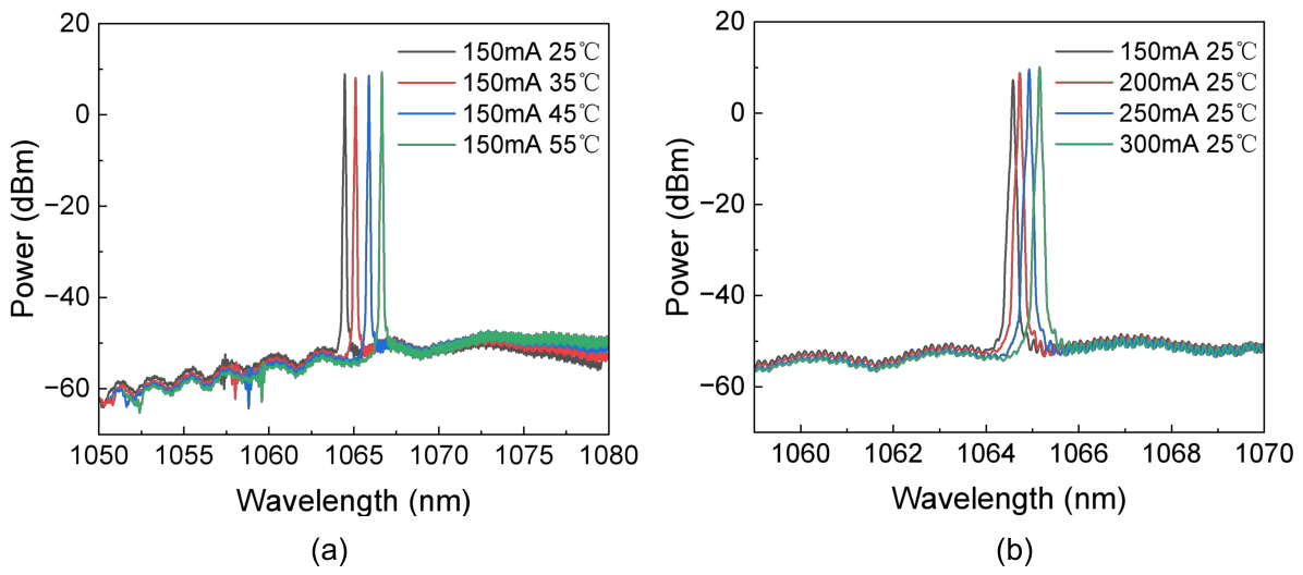
As shown in Figure 5a, rising temperature increases the refractive index of semiconductor materials and elongates the cavity length via thermal expansion. The two combined effects shift the resonant wavelength toward longer wavelengths. As the temperature rises from 25 °C to 55 °C, the central laser wavelength exhibits red-shift toward longer wavelengths. At an injection current of 150 mA, a total wavelength tuning range of 2.18 nm is achieved within 25–55 °C with favorable linear tuning performance. All measured spectra feature sharp single peaks, with background noise approximately ranging from −50 to −60 dBm and a distinct power gap between the main peak and noise floor. The main peak power is far higher than that of side modes. For instance, at 150 mA and 25 °C, the laser operates at a center wavelength of 1064.74 nm and the main peak power is 8.938 dBm while the side-mode power reaches −49.307 dBm, corresponding to a side-mode suppression ratio (SMSR) of 58.2 dB. Consistent results are obtained at other tested temperatures where all SMSR values stay above 58 dB, verifying favorable single-longitudinal-mode performance. Although the main peak intensity slightly decreases and background noise marginally increases with growing temperature, the SMSR remains at a high level without multi-peak splitting or mode hopping, which demonstrates stable single-longitudinal-mode operation of the device across 25–55 °C.
As illustrated in Figure 5b, the central laser wavelength red-shifts toward longer wavelengths as the driving current increases from 150 mA to 300 mA. Increased injection current elevates junction temperature, triggering variations in material refractive index and cavity length to induce wavelength red-shift; meanwhile, altered carrier concentration modulates the bandgap and refractive index and further contributes to red-shift. At 25 °C, a wavelength tuning span of roughly 1 nm is obtained over 150–300 mA. The wavelength varies smoothly with current without any mode hopping during tuning. Spectra measured at all current points maintain single-peak profiles with steady background noise between −50 and −60 dBm. The main peak possesses an extremely narrow linewidth with no spectral broadening, multi-peak generation or mode splitting. Taking the condition of 150 mA and 25 °C as an example, the main peak power is 7.265 dBm and the side-mode power is −49.872 dBm, yielding an SMSR of 57.1 dB. All other tested currents also deliver an SMSR above 57 dB with excellent single-longitudinal-mode characteristics. The main peak power rises prominently with increasing current, yet the spectrum retains a sharp single-peak shape without obvious SMSR degradation. Within 150–300 mA, the device continuously outputs a stable single-longitudinal-mode laser free from mode hopping or multi-longitudinal-mode lasing.

3.4. Linewidth Characterization

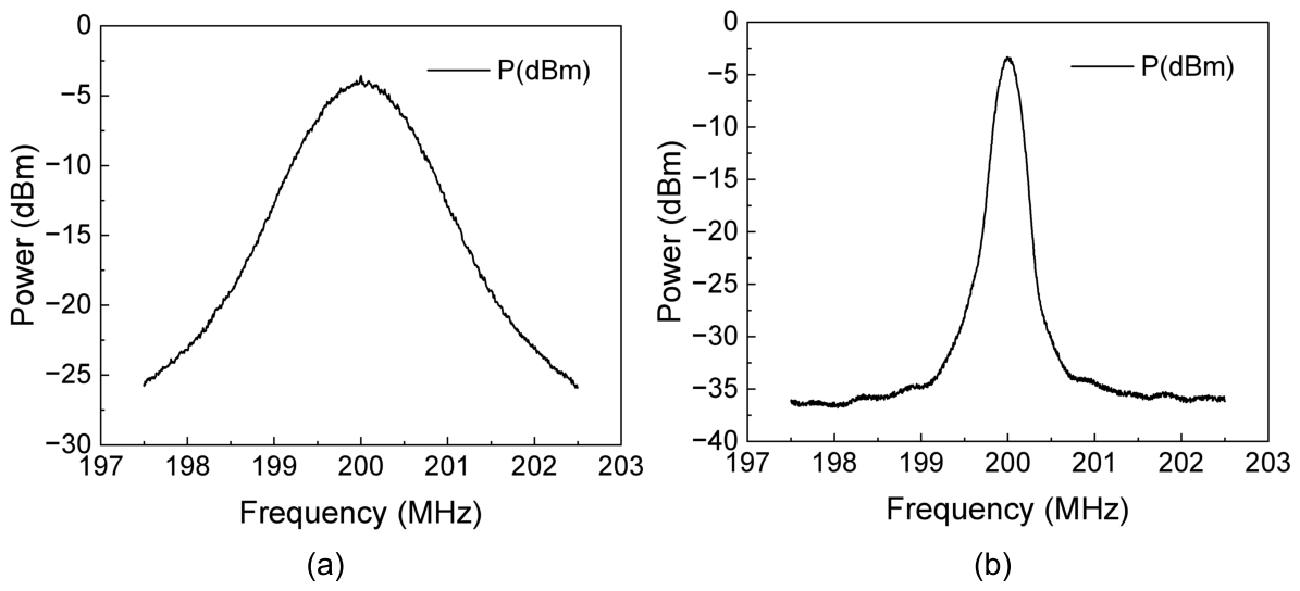
Figure 6a shows the measured linewidth spectrum of the DFB laser packaged with conventional polarization-maintaining fiber. The central frequency is located at 200.00 MHz with a broad Lorentzian spectral profile and a noise floor of −25.90 dBm. The peak power is −3.60 dBm, and the corresponding −3 dB power is −6.60 dBm spanning from 199.56 MHz to 200.53 MHz, giving a −3 dB bandwidth of 0.97 MHz and a laser linewidth of 485 kHz.
Figure 6b presents the linewidth spectrum of the FBG-packaged DFB laser at the central frequency of 200.00 MHz, exhibiting a sharp Lorentzian shape with the noise floor remarkably reduced to −36.70 dBm. The peak power is −3.33 dBm and the corresponding −3 dB power is approximately −6.33 dBm within the frequency range of 199.89 MHz–200.12 MHz, corresponding to a 3 dB bandwidth of 0.23 MHz and a laser linewidth of 115 kHz. Benefiting from FBG optical feedback, the laser linewidth is narrowed from 485 kHz down to 115 kHz with prominent linewidth compression performance.
Via wavelength-selective filtering, suppression of intracavity mode competition and compression of phase noise, FBG feedback optimizes dominant-mode selection. The Bragg reflection wavelength of the fiber grating precisely matches the lasing wavelength of the DFB laser, providing high-reflection feedback exclusively for the dominant mode to filter out the main mode and suppress the gain of spurious side modes. Conventional DFB lasers rely only on internal chip grating for optical feedback, while external FBG feedback boosts the intracavity gain of the dominant mode and enlarges the gain difference between main and side modes. The noise floor in Figure 6b decreases by 10.8 dB accompanied by a notable improvement in side-mode suppression ratio (SMSR). Distributed feedback from the fiber grating locks the laser phase and restrains phase fluctuations induced by carrier noise and thermal noise, thereby compressing spectral linewidth, sharpening spectral peaks and greatly improving laser coherence.
Compared with traditional linewidth reduction technologies such as external cavity frequency locking and ring cavity compression, the FBG packaging scheme possesses irreplaceable engineering merits. Standard fiber packaging only employs chip-inherent feedback, whereas other external-cavity configurations require complicated cavity–fiber coupling which introduces excessive optical loss, poor environmental tolerance and inferior long-term stability. In contrast, the FBG design adopts all-fiber integrated packaging without mechanically adjustable components, featuring high reliability, excellent anti-vibration capability and strong immunity against temperature drift. Furthermore, the fiber grating is directly integrated into the laser pigtail, enabling a compact footprint and easy integration into optical modules and sensing systems. Conventional grating and external-cavity solutions suffer from poor cost competitiveness and limited commercial scalability; by contrast, the FBG-based packaging boasts a mature manufacturing process, low fabrication cost and suitability for mass production. Apart from linewidth narrowing, this scheme improves wavelength stability while inheriting the inherent advantages of DFB lasers including high output power and a low threshold, making it well-suited for commercial applications with stringent requirements on linewidth and wavelength stability such as fiber-optic sensing, coherent optical communication and LIDAR.
The FBG-packaged DFB laser realizes linewidth compression from 485 kHz to 115 kHz at a compression ratio of 4.2:1, which quadruples laser coherence. At a 150 mA injection current and 25 °C ambient temperature, the central wavelength is measured at 1064.58 nm, and no extra frequency drift is introduced by FBG feedback to degrade central wavelength stability. In conclusion, fiber Bragg grating feedback achieves effective laser linewidth reduction.

4. Conclusions

In this paper, the structural design of a 1064 nm DFB semiconductor laser chip, a theoretical analysis on the external-cavity feedback mechanism of fiber Bragg grating (FBG), and development of a butterfly-packaged laser module are accomplished. The influences of operating temperature and driving current on output spectrum, wavelength tuning performance and single-longitudinal-mode characteristics of the device are systematically investigated. Experimental results verify that the fabricated laser features superior optoelectronic performances including a low threshold current of 22.54 mA and favorable linearity of output power, which reaches 80.8 mW at 480 mA. By extending the equivalent cavity length, optimizing mode competition and suppressing phase noise, external FBG feedback enables remarkable laser linewidth narrowing from 485 kHz to 115 kHz while maintaining excellent side-mode suppression ratio as well as stable wavelength tuning against varying temperatures and injection currents. Compared with conventional sole inner-grating DFB configurations and alternative external-cavity architectures, the proposed all-in-one FBG packaged laser integrates merits of narrow linewidth, moderate output power, outstanding operational stability, compact dimension and feasible mass production, alleviating some limitations of conventional narrow-linewidth semiconductor lasers such as insufficient output power and environmental adaptability.
For future research, further optimization of the laser epitaxial structure and grating coupling process can be implemented to reduce intracavity loss and promote output power together with optoelectronic conversion efficiency. Integrated design of a temperature control circuit and driving circuit would facilitate miniaturization, integration and intellectualization of laser modules. In addition, advanced high-precision linewidth tuning approaches can be explored to further reduce the intrinsic laser linewidth. Long-term high–low temperature aging and vibration reliability tests will also be carried out to lay a solid technical foundation for large-scale commercialization in high-end applications including high-precision coherent measurement, long-distance LIDAR and nonlinear frequency conversion.

Author Contributions

Conceptualization, R.G.; methodology, R.G.; validation, R.G. and K.L.; formal analysis, R.G.; investigation, R.G.; data curation, R.G. and K.L.; writing—original draft preparation, R.G.; writing—review and editing, K.L. All authors have read and agreed to the published version of the manuscript.

Funding

This research received no external funding.

Data Availability Statement

Data underlying the results presented in this paper are available and can be obtained from the authors upon reasonable request.

Acknowledgments

The authors are grateful to the Department of Physics, Capital Normal University, for providing experimental platforms. We sincerely acknowledge Wenfeng Sun for his guidance on journal selection and standardization of manuscript format.

Conflicts of Interest

The authors declare no conflicts of interest.

Abbreviations

The following abbreviations are used in this manuscript:
DFBDistributed Feedback
FBGFiber Bragg Grating
SMSRSide-Mode Suppression Ratio

References

  1. Jia, B.S.; Wang, H.; Li, A.M. Narrow-Linewidth 1064 nm Distributed Bragg Reflector Semiconductor Lasers. Chin. J. Lasers 2018, 45, 0501006. [Google Scholar] [CrossRef]
  2. Chen, J.Q.; Liu, Z.H.; Qin, L. Linewidth Measurement of a Narrow-Linewidth Laser: Principles, Methods, and Systems. Sensors 2024, 24, 3656. [Google Scholar] [CrossRef] [PubMed]
  3. Poetzlberger, M.; Zhang, J.W.; Gröbmeyer, S.; Bauer, D.; Sutter, D.; Brons, J.; Pronin, O. Kerr-lens mode-locked thin-disk oscillator with 50% output coupling rate. Optica 2019, 44, 4227–4230. [Google Scholar] [CrossRef]
  4. Zhang, J.W.; Wang, Q.; Hao, J.J.; Liu, H.Y.; Yao, J.Y.; Li, Z.; Liu, J.; Mak, K.F. Broadband, few-cycle mid-infrared continuum based on the intra-pulse difference frequency generation with BGSe crystals. Opt. Express 2020, 28, 37903. [Google Scholar] [CrossRef] [PubMed]
  5. Shang, X.X.; Xu, N.N.; Zong, M.Y.; Yu, W.Y.; Guo, L.G.; Gao, G.G.; Zhang, Z.Q.; Zhang, H.N.; Su, L.Z. ZrGeTe4 Nanoparticles as a Saturable Absorber for Mode-Locked Operations at 1 and 1.55 μm. Photonics 2026, 13, 305. [Google Scholar] [CrossRef]
  6. Xu, N.N.; Zong, M.Y.; Su, L.Z.; Wang, Z.; Yu, W.Y.; Fan, W.Y.; Guo, L.G.; Fu, S.; Shang, X.X.; Zhang, H.N. Nonlinear Optical Properties of Tellurene Nanosheets for Harmonic Soliton Operations in an Er-Doped Fiber Laser. Photonics 2026, 13, 584. [Google Scholar] [CrossRef] [PubMed]
  7. Bai, Z.X.; Zhao, Z.A.; Qi, Y.Y.; Ding, J.; Li, S.S.; Yan, X.S.; Wang, Y.L.; Lu, Z.W. Narrow-Linewidth Laser Linewidth Measurement Technology. Front. Phys. 2021, 9, 768165. [Google Scholar] [CrossRef]
  8. Song, K.M.; Huang, Z.; Zou, Y.G.; Shi, L.L.; Fan, J.; Fu, X.; Sun, T.Y.; Wang, X.Z.; Cheng, B.Y.; Yue, Y.X.; et al. Waveguide array improves a high-power 1550 nm single-mode semiconductor laser. Opt. Laser Technol. 2026, 200, 115202. [Google Scholar] [CrossRef]
  9. Xu, Y.B.; Fu, T.; Fan, J.; Liu, W.Z.; Qu, H.W.; Wang, M.J.; Zheng, W.H. High-Power Supersymmetric Semiconductor Laser with a Narrow Linewidth. Photonics 2023, 10, 238. [Google Scholar] [CrossRef] [PubMed]
  10. Qiu, P.P.; Zhou, H.J.; Wang, Q.H.; Kan, Q. Single-mode narrow-linewidth semiconductor laser based on oxidized aperture and shallowly etched slots. Opt. Laser Technol. 2026, 200, 115143. [Google Scholar] [CrossRef]
  11. Dai, Y.Q.; Fu, T.; Chen, J.X.; Tang, C.Y.; Wang, X.Y.; Wang, Y.F.; Zheng, W.H. Topological robustness of a high-power narrow linewidth semiconductor laser based on the Su–Schrieffer–Heeger model. Appl. Opt. 2025, 64, 4678–4684. [Google Scholar] [CrossRef] [PubMed]
  12. Wang, S.; Lv, Z.R.; Wang, S.L.; Chai, H.Y.; Liu, W.L.; Jiang, K.H.; Yang, X.G.; Yang, T. High power lateral coupled InAs/GaAs quantum dot distributed feedback lasers grown on Si(001) substrates. Opt. Express 2024, 32, 34444. [Google Scholar] [CrossRef] [PubMed]
  13. Aoyama, K.; Kobayashi, S.; Wada, M.; Yokota, N.; Kita, T.; Yasaka, H. Compact narrow-linewidth optical negative feedback laser with Si optical filter. Appl. Phys. Express 2018, 11, 112703. [Google Scholar] [CrossRef]
  14. Gu, Z.Q.; Hu, J.H.; Jia, H.L.; Yang, Z.; Chen, C.X.; Zhang, H.Y.; Li, Z.X.; Zha, L.L.; Du, F.N.; Hu, F.C.; et al. GaN-based lateral-coupled distributed feedback laser diode with large bandwidth and narrow linewidth. Photonics Res. 2026, 14, 666. [Google Scholar] [CrossRef]
  15. Abdullaev, A.; Lu, Q.; Guo, W.; Wallace, M.J.; Nawrocka, M.; Bello, F.; Benson, A.; O’Callaghan, J.R.; Donegan, J.F. Improved performance of tunable single-mode laser array based on high-order slotted surface grating. Opt. Express 2015, 23, 12072–12078. [Google Scholar] [CrossRef] [PubMed]
  16. Li, J.; Wang, X.; Xu, Y.B.; Du, F.L.; Wang, M.; Wang, H.L. Single-Mode Laser with Chirped Photonic Crystal Structure Based on Standard Photolithography. IEEE Photonics Technol. Lett. 2022, 34, 1608–1611. [Google Scholar] [CrossRef]
  17. Chen, Y.M.; Cong, Q.Y.; Jia, L.X. Wavelength-Tunable Silicon Nitride External-Cavity Semiconductor Laser. Chin. J. Lasers 2024, 51, 1301009. [Google Scholar]
  18. Schawlow, A.L.; Townes, C.H. Infrared and Optical Masers. Phys. Rev. 1958, 112, 1940–1949. [Google Scholar] [CrossRef]
  19. Bagheri, M.; Spiers, G.D.; Frez, C.; Forouhar, S.; Aflatouni, F. Linewidth Measurement of Distributed-Feedback Semiconductor Lasers Operating Near 2.05 μm. IEEE Photonics Technol. Lett. 2015, 27, 1934–1937. [Google Scholar] [CrossRef]
  20. Zhao, Z.; Bai, Z.; Jin, D. The Influence of Noise Floor on the Measurement of Laser Linewidth Using Short-Delay-Length Self-Heterodyne and Homodyne Techniques. Micromachines 2022, 13, 1311. [Google Scholar] [CrossRef] [PubMed]
  21. Wang, K.N.; Liu, Y.L.; Chen, H.B. Linewidth Measurement of Distributed-Feedback Lasers by Frequency-Shifted Delayed Self-Heterodyne Method. Laser Technol. 2018, 42, 633–637. [Google Scholar]
  22. Yu, B.L.; Yang, J.R.; Yang, Y.H. Zero-Beat Measurement of Narrow-Linewidth Lasers. Chin. J. Lasers 2001, 28, 351–354. [Google Scholar]
  23. Xiao, H.J.; Wang, X.; Ma, Y. Linewidth Measurement of Narrow-Linewidth Fiber Laser Based on Delayed Self-Heterodyne Interferometry. Opto-Electron. Eng. 2010, 37, 57–61. [Google Scholar]
Figure 1. (a) Gain spectrum of quantum wells; (b) epitaxial structure of the laser chip.
Photonics 13 00677 g001
Figure 2. (a) Photograph of the 1064 nm DFB laser chip; (b) schematic diagram of the packaged device.
Photonics 13 00677 g002
Figure 3. Schematic diagram of measurement setup based on delayed self-heterodyne method.
Photonics 13 00677 g003
Figure 4. (a) Output spectrum of the device; (b) PIV characteristic curve of the device.
Photonics 13 00677 g004
Figure 5. (a) Spectra of FBG-packaged DFB laser at different temperatures; (b) spectra of FBG-packaged DFB laser under different injection currents.
Photonics 13 00677 g005
Figure 6. (a) Linewidth measurement results of DFB laser packaged with conventional polarization-maintaining fiber; (b) linewidth measurement results of DFB laser packaged with fiber Bragg grating.
Photonics 13 00677 g006
Table 1. Recently reported narrow-linewidth semiconductor lasers.
ReferencesNarrowing MethodLinewidthOutput PowerSMSR
[8]Waveguide array with grating1.8 MHz60 mW40 dB
[9]Supersymmetric slots230 kHz113 mW48.5 dB
[10]Surface slots638 kHz20 mW42 dB
[11]Three-defect Su–Schrieffer–Heeger structure2 MHz54.6 mW40.4 dB
[12]Lateral coupled grating243 kHz25 mW56.5 dB
[13]Si optical filter160 kHz//
[14]Lateral coupled grating2.6 MHz90 mW22 dB
[15]Slotted surface grating groups500 kHz6.7 mW50 dB
[16]Chirped photonic crystal1 MHz33 mW45 dB
This workDFB-FBG115 kHz80.8 mW58.2 dB
Our proposed method is highlighted in bold font.
Disclaimer/Publisher’s Note: The statements, opinions and data contained in all publications are solely those of the individual author(s) and contributor(s) and not of MDPI and/or the editor(s). MDPI and/or the editor(s) disclaim responsibility for any injury to people or property resulting from any ideas, methods, instructions or products referred to in the content.