Design of a Dual-Band Infrared Continuous Zoom Optical System with Chromatic Aberration Compensation for Room-Temperature Infrared Photoelectric Applications

Abstract
1. Introduction
2. Chromatic Aberration Compensation Method for Dual-Band Infrared Continuous Zoom Optical System
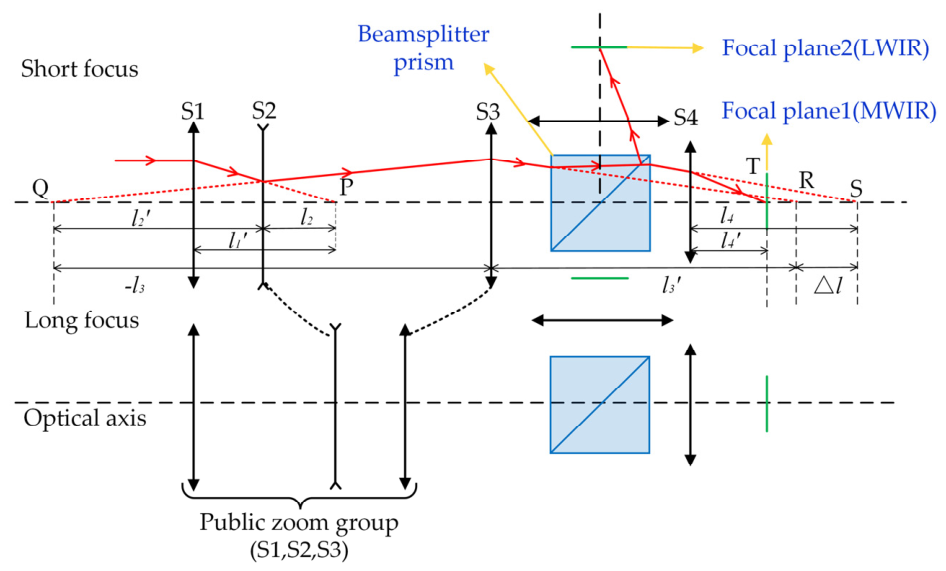
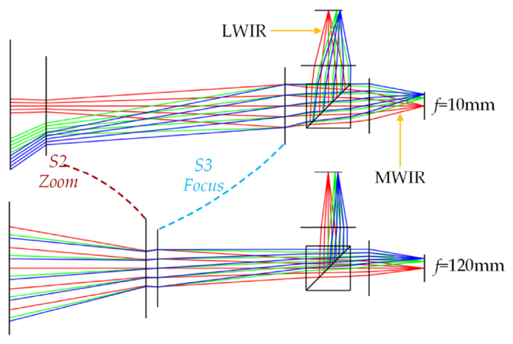
2.1. Zoom Principle of Dual-Band Infrared Continuous Zoom Optical System
2.2. Chromatic Aberration Compensation Method for Dual-Band Infrared Continuous Zoom Optical System
2.3. Calculation Method for Initial Structural Parameters with Chromatic Aberration Compensation
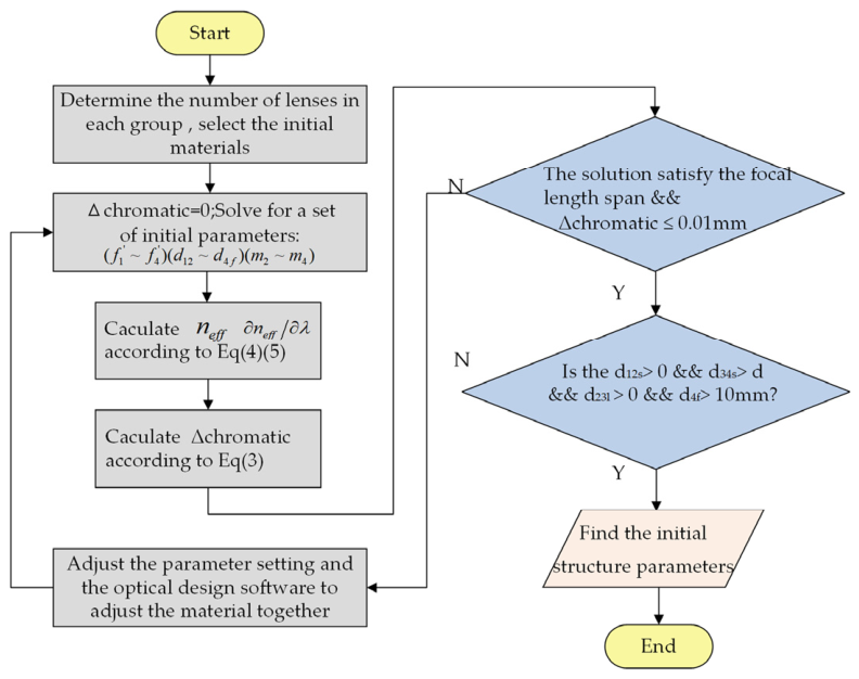
- First, set and solve for a set of initial structural parameters. The solutions include , and .
- Based on the first-round solution obtained in step (1), the lens count and initial material of each group are assigned according to group function. Then, and are calculated from the properties of the selected materials. By substituting the initial structural parameters from step (1) into Equation (3), the first-round value of is obtained.
- The updated is substituted back into the zoom equation to form a coupled equation set. An infrared glass library satisfying the dual-band requirements is then established, and a material substitution search is performed in Zemax 2022R2.01. The assumed focal powers, magnifications, and material combinations are then adjusted jointly. The iteration continues until < 0.01 mm, yielding an initial low chromatic aberration structure. Finally, the constraints are checked to ensure , , , > 15 mm, and they confirm that no mechanical interference occurs during zooming.
3. Design Example of an Achromatic Dual-Band Infrared Continuous Zoom Optical System
3.1. Design Index
3.2. Calculating the Initial Structure of the Optical System
- The short focal length = 10 mm, long focal length = 120 mm, and total length = 150 mm are known parameters. The focal lengths of four groups; the intervals at the short and long focal lengths, namely and ; and the magnification , are the unknown parameters to be solved. The design must avoid mechanical interference at the extreme zoom positions and reserve sufficient back focal length for the detector. Accordingly, a system of equations is established to solve the initial structural parameters.Including and in the set of equations both prevents mechanical interference during zooming and simplifies the calculation. The beam splitter prism is modeled using ZNS_BROAD as the substrate material, with a refractive index of 2.25 and a thickness of 16 mm. ZNS_BROAD was selected because it covers both the MWIR and LWIR bands and is suitable for use in infrared beam-splitting components.
- Solve for the short-focus parameters. Equation (14) comprises four equations with seven variables, with constraints > 10 mm and > 15 mm. Set the focal length of S1 and the magnification of S4, assuming . Set to approximately 15% of the total length and initially set . Based on the first-round solution, is evaluated and substituted back into the equations to iteratively update the initial structural parameters until the stopping criterion is met. The resulting short-focus structural parameters are then substituted into Equation (13) to calculate the corresponding group spacings, and . The solutions may vary with different parameter settings, which are only used as one set of trial solutions.
- After the short-focus parameters and are obtained, the long-focus parameters can be calculated. Substitute the unknown long-focus parameters into Equation (14) to express the total length L and the long focal length . Together with Equation (11), solve for . Then, substitute these results into Equation (13) to obtain the interval at long focus.
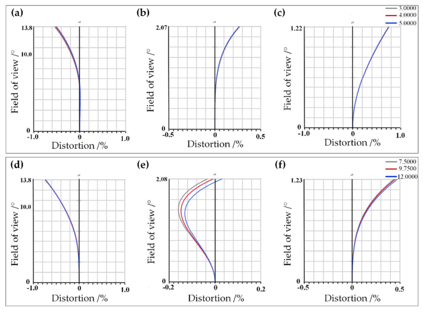
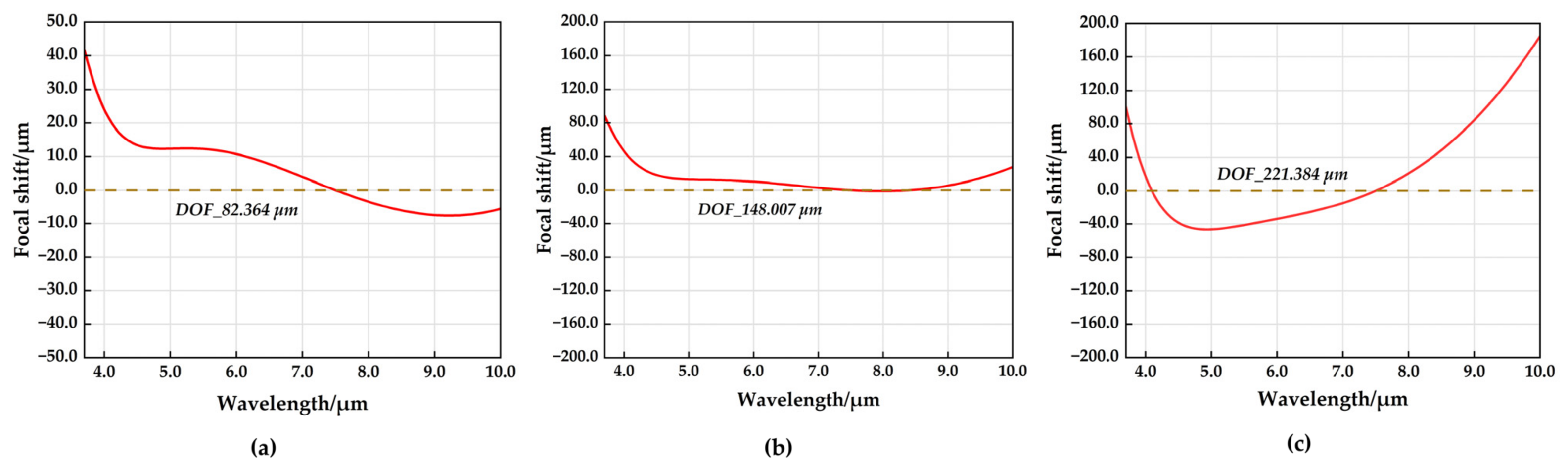
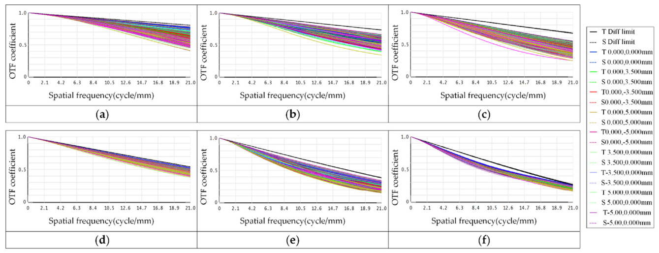
- The obtained parameters are imported into Zemax OpticStudio to build the continuous zoom optical model. Then, optimize the model by writing an evaluation merit function until the MTF, distortion, and chromatic aberration satisfy the application requirements.
4. Optimized Design and Performance Evaluation of Optical System
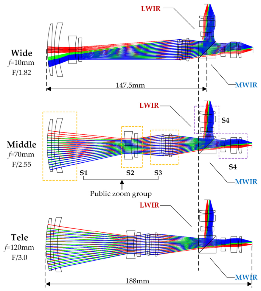
4.1. Optimization Strategy and Design Results
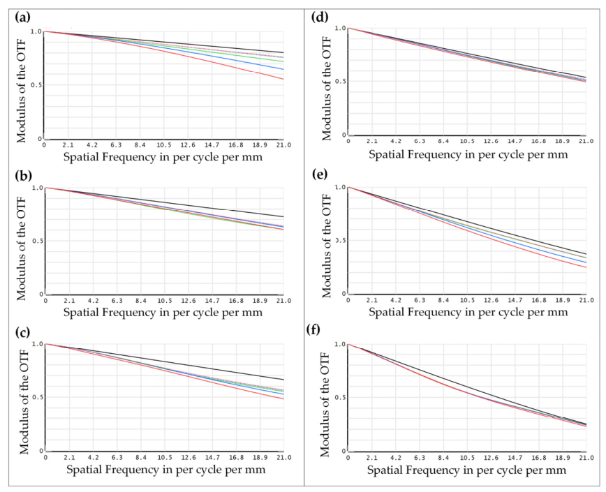
4.2. Image Quality Evaluation
4.3. Motion Curve and Full Zoom Image Quality Consistency Analysis
4.4. Tolerance Analysis
5. Conclusions
Author Contributions
Funding
Institutional Review Board Statement
Informed Consent Statement
Data Availability Statement
Conflicts of Interest
References
- Wang, C.F.; Wang, X.W.; Lu, W.G. Design of two-color cold infrared optical system. Infrared Laser Eng. 2023, 52, 156–164. [Google Scholar]
- Neil, I.A. Evolution of zoom lens optical design technology and manufacture. Opt. Eng. 2021, 60, 051211. [Google Scholar] [CrossRef]
- Vizgaitis, N.J.; Hastings, A. Dual-band infrared picture-in-picture systems. Opt. Eng. 2013, 52, 061306. [Google Scholar] [CrossRef]
- Pozzi, P.; Quintavalla, M.; Wong, A.; Borst, J.G.G.; Bonora, S.; Verhaegen, M. Plug-and-play adaptive optics for commercial laser scanning fluorescence microscopes based on an adaptive lens. Opt. Lett. 2020, 45, 3585–3588. [Google Scholar] [CrossRef]
- Ma, C.; Li, Y.; Wu, S.; Xue, C. Design of a three-component movable continuous zoom hybrid system with a double-layer diffractive optical element in a dual-band. Appl. Opt. 2025, 64, 64–71. [Google Scholar] [CrossRef]
- Tanaka, K. Paraxial analysis of mechanically compensated zoom lenses. 1: Four-component type. Appl. Opt. 1982, 21, 2174–2183. [Google Scholar] [CrossRef]
- Qu, R.; Duan, J.; Liu, K.; Cao, J.; Yang, J. Optical Design of a 4× Zoom Lens with a Stable External Entrance Pupil and Internal Stop. Photonics 2022, 9, 191. [Google Scholar] [CrossRef]
- Mikš, A.; Novák, P. Paraxial design of a four-component zoom lens with zero separation of principal planes and fixed position of an image focal point composed of members with constant focal length. Appl. Opt. 2019, 58, 3957–3961. [Google Scholar] [CrossRef]
- Park, S.; Lee, S.; Kim, J. Compact zoom lens design for a 5× mobile camera using prism. J. Opt. Soc. Korea 2009, 13, 206–212. [Google Scholar] [CrossRef]
- Chen, Y.; Gao, M.; Song, X. Method to design the common-aperture multiband optical system based on the PSO algorithm. Opt. Express 2021, 29, 18325–18335. [Google Scholar] [CrossRef] [PubMed]
- Li, X.; Liu, J.; Chen, Y. Design of a dual-band, High Zoom Ratio and continuous co-focal optical system. Acta Photonica Sin. 2016, 45, 52–61. [Google Scholar]
- Zhang, B.; Cui, Q.; Piao, M.; Hu, Y. Design of dual-band infrared zoom lens with multilayer diffractive optical elements. Appl. Opt. 2019, 58, 2058–2067. [Google Scholar] [CrossRef]
- Geng, H.; Yu, L.; Zhang, B. Design of cooled infrared dual-band zoom optical system with large-magnification-ratio. Chin. Opt. 2024, 17, 1431–1441. [Google Scholar] [CrossRef]
- Lu, L.; Wang, Y.; Luo, X.; Yao, L. Design of a dual-band co-aperture synchronous zoom security optical system. Appl. Opt. 2025, 64, 2144–2151. [Google Scholar] [CrossRef]
- Qu, R.; Zhang, H.; Guo, H.; Li, J. 30× VIS-SWIR wideband zoom lens design (invited). Infrared Laser Eng. 2024, 53, 65–71. [Google Scholar]
- Salinas, C.M.; Sisterson, R.; Jordan, S.; Moore, S.; Wiley, L. Infrared Lens Selection Using Weighted Dispersion Derivative. Opt. Eng. 2025, 64, 095103. [Google Scholar] [CrossRef]
- Qian, Z.; Wang, B.; Xia, B.; He, Z.; Lei, X.; Xu, J.; Gu, J.; Shen, X.; Wang, S. MWIR-LWIR Dual-Band Imaging System with Hybrid Refractive-Diffractive-Metasurface Optics for Spatially Separated Focal Planes. Chin. Opt. Lett. 2025, 23, 42–48. [Google Scholar] [CrossRef]
- Hao, J.; Xin, Y.; He, Z.; Liu, S.; Mao, S. Simplified See-Through Head-Mounted Display Optics with Achromatic Metalens. Photonics 2026, 13, 229. [Google Scholar] [CrossRef]
- Li, J.; Zhang, K.; Yu, F.; Yu, S.; Zhang, X.; Sun, S.; Chen, Q.; Yan, W. Design of the dual-band shared-aperture asynchronous zoom optical system using focus tunable lenses. Opt. Express 2023, 31, 30710–30722. [Google Scholar] [CrossRef] [PubMed]
- Liu, Y.; Yang, B.; Guo, P.; Wang, X.; Zong, H. 50× five-group inner-focus zoom lens design with focus tunable lens using Gaussian brackets and lens modules. Opt. Express 2020, 28, 29098–29111. [Google Scholar] [CrossRef]
- Zhang, K.; Qu, Z.; Zhong, X.; Li, J.; Zhang, Q. Design of a 30× compact zoom optical system. Opt. Precis. Eng. 2022, 30, 1263–1271. [Google Scholar] [CrossRef]
- Qu, R.; Guo, H.; Cao, J.; Yang, J. Design of a visible–near-infrared athermal continuous zoom optical system. Infrared Laser Eng. 2021, 50, 249–255. [Google Scholar]
- Zhang, K.; Li, J.; Zhang, X.; Wang, J.; Sun, S. Design method of dual-band synchronous zoom optical system based on co-path zoom groups. Opt. Lasers Eng. 2023, 170, 107791. [Google Scholar] [CrossRef]
- Zhang, K.; Qu, Z.; Zhong, X.; Li, F.; Yu, S. 40× zoom optical system design based on stable imaging principle of four groups. Appl. Opt. 2022, 61, 1516–1522. [Google Scholar] [CrossRef] [PubMed]
- Zhang, K.; Li, J.; Si, S.; Wang, J.; Yu, S. Optical system design of double-sided telecentric microscope with high numerical aperture and long working distance. Opt. Express 2023, 31, 23518–23532. [Google Scholar] [CrossRef] [PubMed]




| Material | Spectral Range/ µm | Refractive Index | µm−1 | ||
|---|---|---|---|---|---|
| 4 µm | 10 µm | 4 µm | 10 µm | ||
| Ge | 2.0~17 | 4.0250 | 4.0043 | −0.0122 | −0.0009 |
| ZNS_BROAD | 0.37~14 | 2.2524 | 2.1999 | −0.0056 | −0.0130 |
| ZNSE | 0.55~20 | 2.4331 | 2.4064 | −0.0038 | −0.0061 |
| GASIR1 | 1.0~14 | 2.5116 | 2.4959 | −0.0035 | −0.0031 |
| AMTIR-1 | 0.75~14 | 2.5136 | 2.4970 | −0.0035 | −0.0033 |
| AMTIR-2 | 1.0~14 | 2.7867 | 2.7700 | −0.0050 | −0.0027 |
| AMTIR-3 | 1.0~14 | 2.6210 | 2.6022 | −0.0044 | −0.0036 |
| IG2 | 0.75~14 | 2.5133 | 2.4967 | −0.0035 | −0.0034 |
| IG4 | 0.8~14 | 2.6220 | 2.6090 | −0.0037 | −0.0022 |
| IG5 | 0.85~14 | 2.6221 | 2.6032 | −0.0043 | −0.0036 |
| IG6 | 0.85~14 | 2.7945 | 2.7775 | −0.0058 | −0.0027 |
| Parameters | Value |
|---|---|
| Working band | MWIR 3.7~4.8 μm |
| LWIR 8~10 μm | |
| Focal length | 10~120 mm |
| Distortion | ≤3% |
| Chromatic focal shift | ≤ |
| Zoom ratio | 12× |
| Pixel size | 25 µm |
| Back focal length | ≥10 mm |
| S1 | S2 | S3 | S4 | |
|---|---|---|---|---|
| EFL/mm | 85.000 | −22.500 | 40.637 | 40.000 |
| d12 | d23 | d34 | d4f | |
|---|---|---|---|---|
| Short focus = 10 mm | 13.000 | 86.524 | 30.535 | 20.000 |
| Long focus = 120 mm | 49.368 | 4.231 | 76.401 | 20.000 |
| Surface | Radius/mm | Thickness/mm | Material | |
|---|---|---|---|---|
| S1 | 1 | 97.73 | 3.98 | IG4 |
| 2 | 271.25 | 2.39 | ||
| 3 | 106.87 | 4.03 | ZNS_BROAD | |
| 4 | 80.11 | 9.80–64.29 | ||
| S2 | 5 | −85.58 | 5.49 | GASIR1_M |
| 6 | 45.92 | 2.73 | ||
| 7 | 108.34 | 3.26 | IG6 | |
| 8 | 251.33 | 88.33–4.98 | ||
| stop | 9 | Infinity | 1.00 | |
| S3 | 10 | 42.74 | 2.62 | IG6 |
| 11 | −240.99 | 1.51 | ||
| 12 | −84.92 | 2.48 | GERMANIUM | |
| 13 | −1300.01 | 1.84 | ||
| 14 | −60.10 | 2.46 | ZNSE | |
| 15 | −36.98 | 7.74–36.60 | ||
| S4 | 21 | −74.44 | 3.33 | ZNS_BROAD |
| 22 | 24.58 | 5.26 | ||
| 23 | 87.22 | 6.02 | GASIR2 | |
| 24 | −75.00 | 1.24 | ||
| 25 | 25.69 | 2.49 | IG4 | |
| 25 | 75.151 | 11.23 |
| Surface No. | Conic | 4th-Order Term | 6th-Order Term | 8th-Order Term |
|---|---|---|---|---|
| 3 | −0.776 | −1.308 × 10⁻⁷ | 5.858 × 10⁻¹⁰ | −1.075 × 10⁻¹² |
| 6 | −9.317 | −8.887 × 10⁻⁶ | 5.712 × 10⁻⁸ | −9.078 × 10⁻¹⁰ |
| 7 | −1.499 | −9.386 × 10⁻⁶ | 1.953 × 10⁻⁸ | −2.091 × 10⁻¹⁰ |
| 10 | 2.354 | 7.484 × 10⁻⁶ | −1.124 × 10⁻⁸ | −4.164 × 10⁻¹⁰ |
| 12 | 32.480 | −9.154 × 10⁻⁶ | 9.677 × 10⁻⁸ | −2.545 × 10⁻¹⁰ |
| 15 | 0.762 | −3.298 × 10⁻⁶ | 3.030 × 10⁻⁸ | −1.456 × 10⁻¹⁰ |
| 21 | 39.9998 | −1.388 × 10⁻⁵ | 1.555 × 10⁻⁶ | −6.814 × 10⁻⁸ |
| Tolerance | Items | Values |
|---|---|---|
| Thickness | Thickness/mm | ±0.025 |
| Surface quality | Radius (fringe) | ±1 |
| Irregularity (fringe) | ±0.2 | |
| Material | Abbe number (%) | ±1 |
| Refraction index | ±0.001 | |
| Surface tolerances | Decenter/mm | ±0.01 |
| Tilt (′) | ±0.01 | |
| Element | Decenter/mm | ±0.03 |
| Tilt (′) | ±0.03 |
Disclaimer/Publisher’s Note: The statements, opinions and data contained in all publications are solely those of the individual author(s) and contributor(s) and not of MDPI and/or the editor(s). MDPI and/or the editor(s) disclaim responsibility for any injury to people or property resulting from any ideas, methods, instructions or products referred to in the content. |
© 2026 by the authors. Licensee MDPI, Basel, Switzerland. This article is an open access article distributed under the terms and conditions of the Creative Commons Attribution (CC BY) license.
Share and Cite
Wan, Z.; Ye, B.; Zou, Y.; Cao, H.; Yin, S. Design of a Dual-Band Infrared Continuous Zoom Optical System with Chromatic Aberration Compensation for Room-Temperature Infrared Photoelectric Applications. Photonics 2026, 13, 447. https://doi.org/10.3390/photonics13050447
Wan Z, Ye B, Zou Y, Cao H, Yin S. Design of a Dual-Band Infrared Continuous Zoom Optical System with Chromatic Aberration Compensation for Room-Temperature Infrared Photoelectric Applications. Photonics. 2026; 13(5):447. https://doi.org/10.3390/photonics13050447
Chicago/Turabian StyleWan, Zijie, Bo Ye, Yangkun Zou, Honggui Cao, and Shaoda Yin. 2026. "Design of a Dual-Band Infrared Continuous Zoom Optical System with Chromatic Aberration Compensation for Room-Temperature Infrared Photoelectric Applications" Photonics 13, no. 5: 447. https://doi.org/10.3390/photonics13050447
APA StyleWan, Z., Ye, B., Zou, Y., Cao, H., & Yin, S. (2026). Design of a Dual-Band Infrared Continuous Zoom Optical System with Chromatic Aberration Compensation for Room-Temperature Infrared Photoelectric Applications. Photonics, 13(5), 447. https://doi.org/10.3390/photonics13050447