1. Introduction
Spatial diffraction and temporal dispersion are inherent properties of light waves, fundamentally leading to the spatial or temporal broadening of localized wave packets during propagation [
1,
2,
3]. The diffraction- or dispersion-induced redistribution of light field from its on-axis region into surrounding areas considerably reduces the contrast between the central intensity peak and the background field, thereby limiting spatial and temporal resolution as well as the field of view in various optical systems [
4,
5]. Since the first experimental realization of the nondiffracting Bessel beam by Durnin et al. in 1987 [
6,
7]—generated through conical superposition of many plane wave components—considerable efforts have been devoted to overcoming the optical diffraction [
8] and dispersion [
9,
10]. Particularly, analytical solutions of the paraxial Helmholtz equation in different coordinate systems have given rise to several families of the nondiffracting light beams, including the Airy beams [
11], Mathieu beams [
12], and Weber beams [
13]. These beams can self-accelerate in space, fundamentally different from the Bessel beam that propagates only along a straight line [
6,
7]. All the mentioned nondiffracting light beams exhibit self-healing property, namely they can restore their original wave forms during propagation even though they are partially blocked at their initial stage of propagation [
14]. The concept of nondiffracting beams has been extended to other physical systems, leading to the generations of nondiffracting surface plasmon polariton waves [
15] and acoustic waves [
16] in space, as well as the nonspreading surface gravity water waves [
17,
18] and matter waves [
19] in time. Owing to their distinctive features, nondiffracting wave packets have found wide applications in optical trapping [
20], super-resolution imaging [
21], plasma channel formation [
22], and beyond.
Despite recent progress in this particular research field, most generated nondiffracting light beams exhibit transverse dimensions that are much larger than the optical wavelength. These relatively large-version nondiffracting light beams become uncompetitive in various optical nanotechnologies including nano-scale microscopy [
23], nano-scale fabrication [
24], and particle manipulation [
25], as well as those associated with nano-scale light–matter interactions [
26]. Therefore, the next challenge is to achieve the nondiffracting light beams at the subwavelength scale. Regarding this fundamental issue, it has been shown that one can exploit the surface plasmon polariton in the metallic system, which exhibits higher-spatial-frequency wave vector than the free-space one [
27], allowing to produce much localized surface wave packet by interfering these higher-spatial-frequency components. Particularly, by appropriately arranging these high-spatial-frequency components on the metallic surface, one can generate the subwavelength nondiffracting beams [
28,
29]. However, these kinds of nondiffracting beams were realized in the (near-field) evanescent region, exponentially decaying along their propagation distance. To overcome this limitation, far-field approaches have been proposed and experimentally demonstrated. For example, metasurface with sharp-edge elements has been designed to excite propagating high-spatial-frequency waves [
30] (different from the evanescent ones excited in the near field), giving rise to the generation of deep-subwavelength structured light in the far field [
31,
32]. In addition, some have considered utilizing the quantum superoscillatory phenomenon (a far-field quantum wave phenomenon of a band-limited wave function which locally oscillates at a frequency faster than its maximum Fourier component [
33]) to realize the superoscillatory light fields with deep-subwavelength feature sizes [
34,
35]. These far-field superoscillatory light fields can be achieved and made nondiffracting during propagation in space, with particularly designed subwavelength structures [
36,
37] and diffractive optical elements [
38,
39]. Nevertheless, these far-field approaches often encounter a serious problem that the generated subwavelength main lobe of the light field is inevitably accompanied with strong sidelobes [
32,
40], thereby considerably reducing subwavelength light contrast, which limits its potential applications.
In this work, we propose and demonstrate a randomly perturbed sharp-edge aperture, capable of generating high-contrast nondiffracting light beams at the subwavelength scale. The proposed structure includes a basic circular disc with sharp edges, which is used to excite the propagating high-spatial-frequency wave vectors with cylindrically symmetric distribution in the Fourier space. The constructive interference between these in-phase high-spatial-frequency components results in a tightly confined nondiffracting light needle with feature size at the subwavelength scale. On the other hand, our designed sharp-edge structure comprises slit motifs, separately distributed in rotationally symmetric positions that are surrounding the basic circular disc. The slit width of these individual motifs varies randomly, allowing us to realize the destructive interference between the zero-order diffractive components emerging from the sharp-edge diffraction of the structure, while maintaining the constructive interference of the high-spatial-frequency diffractive components along the on-axis positions. As a result, we are able to form a high-contrast nondiffracting light beam in the subwavelength-scale regime. The presented mechanism offers a robust and effective route toward the generation of the high-contrast subwavelength nondiffracting structured light, paving the way for future advanced applications such as in the optical super-resolution imagings, and nano-particle manipulations.
2. Working Principle
To realize the high-contrast subwavelength nondiffracting light beams, it is essential to achieve coherent superposition among these high-spatial-frequency diffractive components while randomizing the phase of the zero-order diffractive components in the course of sharp-edge diffraction. At the beginning, we consider a sharp-edge obstacle to excite these high-spatial-frequency diffractive components, which propagate to the far field. Specifically, we consider an incident optical wave, which is partially cut by the sharp-edge obstacle. At a local position near the sharp edge, the incident light field features an abrupt change when it hits the edge of the obstacle, described by a step function
, where
represents the local position of the sharp edge. Such a step wave function leads to an abrupt phase change, which, due to prominent spatial phase gradient effect, produces abundant high-spatial-frequency diffractive components. From the view of the Fourier space, the Fourier transform of the step function indicates that the abrupt-change wave function exhibits a continuous higher-order diffractive components in addition to the zero-order one, all of which are able to propagate to the far field region. To ensure that these high-order diffractive components interfere constructively, their diffractive wave vectors must exhibit a cylindrically symmetric distribution in the reciprocal (Fourier) space. This requires a circular sharp-edge obstacle with its radius denoted as
. Thus, we realize abrupt phase change around the circle, generating the cylindrically symmetric diffractive wave vectors. Mathematically, the basic circular obstacle can be described as
, where
and
denotes a circle function, meaning that the function equals 1 if
and 0 elsewhere. The geometric distribution of the sharp-edge obstacle is schematically depicted in
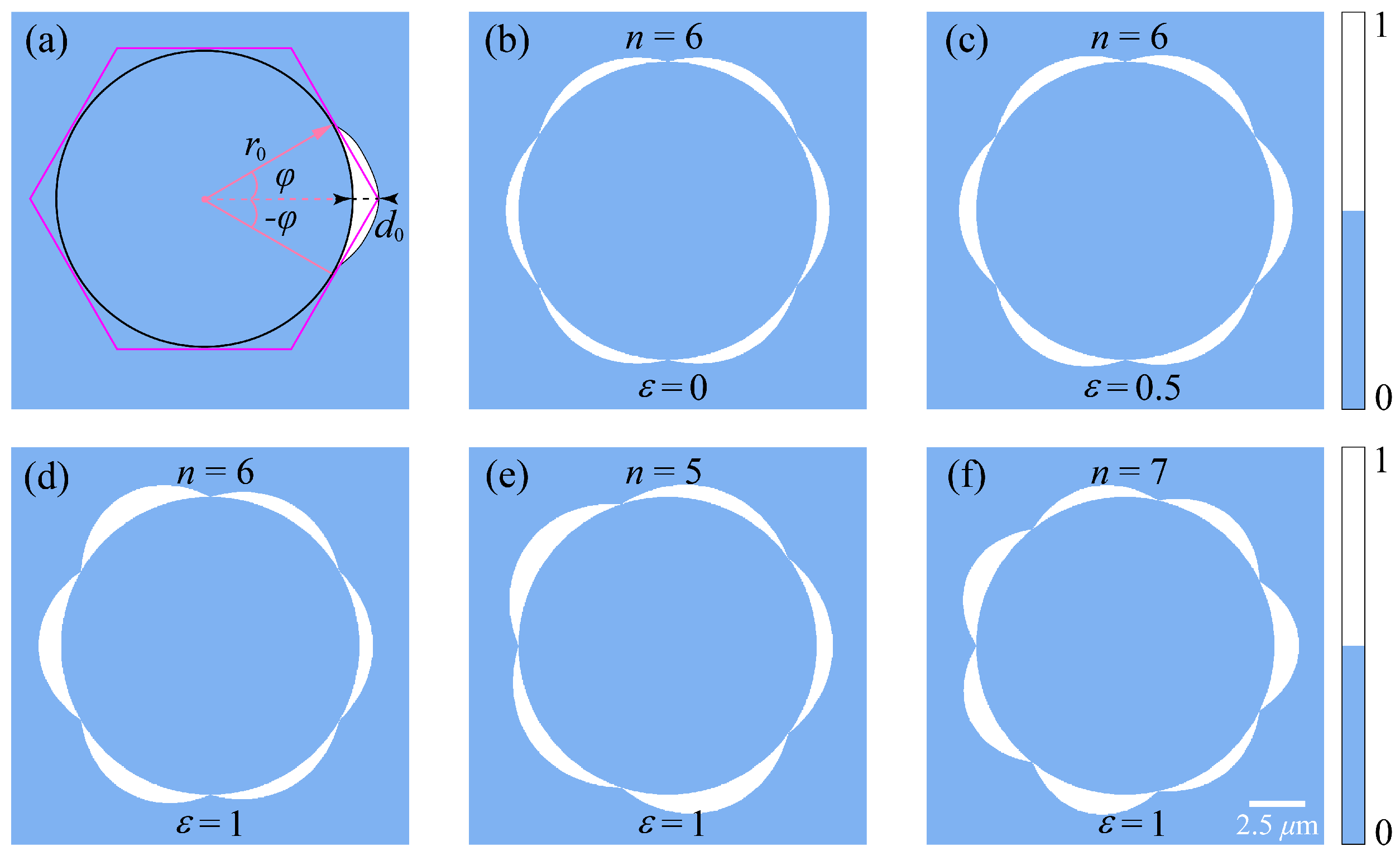
Figure 1a.
In this circular sharp-edge configuration, not all the incident energy of light wave can be efficiently concentrated into the central (on-axis) spot by the circular obstacle through sharp-edge diffraction. Instead, a substantial portion of the energy is redistributed into the surrounding background through the interference of the zero-order diffractive components, namely the low-spatial-frequency components. This leads to a degraded focal contrast along the on-axis positions, as the intensity of the central main lobe is covered by the strong background field. To suppress these unwanted side lobes (the background light field), we modify the sharp-edge structure by including several sharp-edge slit motifs appropriately placed around the basic circular disc. This inclusion allows us to realize the destructive interference of these zero-order diffractive components while maintaining the constructive interference among the high-spatial-frequency diffractive components along the on-axis positions.
Specifically, the sharp-edge slit motifs (numbered as
) are symmetrically distributed around the circular obstacle, with their angle locations expressed as
.
Figure 1a illustrates one of these slit motifs with its angle position located at
with respect to horizontal direction; see the red dashed curve in
Figure 1a. To disturb the phase of the zero-order diffractive components emerging from the basic circular obstacle, the spatial width of the individual slit motifs should be spatially varying. To achieve this purpose, we assume that the width of the individual slit motifs is dependent on the azimuthal angle
, defined as
. In this case, we describe the width of the slit motifs as
where
represents the maximum width of the slit motifs and
denotes an angle range that the slit motif covers, as displayed in
Figure 1a. It is expressed as
, determined by the number of the slit motifs (or the rotationally symmetric order). Thus, the angle
varies between
and
. In this case, we obtain the following relation:
, in each case of the slit motif. This setting indicates that the introduced slit motif connects the vertices of the
n-fold regular polygon circumscribed around the inner disc, as shown in
Figure 1a. Equation (
1) shows that the width of the sharp-edge slit grows gradually with an increase of
and then reaches its maximum value of
and finally decreases gradually with
. We emphasize here that the annular region between
and
is completely transparent, while the outer region remains opaque. Such abrupt changes of amplitude and phase of the incident light field allow to generate abundant high-spatial-frequency components that propagate to the far field region. Using such a designed principle, we obtain the complete sharp-edge slit motifs symmetrically surrounding the circle. As an illustration,
Figure 1b depicts a 6-fold slit-motif pattern (
). It is evident that these slit motifs exhibit identical structural parameters and rotationally symmetric distribution in the transverse plane.
We note that such a slit-motif pattern is insufficient to obtain the high-contrast subwavelength focal spot, since, to some extent, these regular slit motifs (they exhibit periodicity along the azimuthal angle
) still produce constructive interference among the zero-order diffractive components. In the following, we further disturb these in-phase interference effects by randomizing these slit motifs. To this end, we carefully break the structural symmetry in the azimuthal direction by introducing a random slit width. To achieve this, the maximum slit width
in the individual slit motifs (see Equation (
1)) is replaced by the following one:
where
denotes a uniformly distributed random variable with value ranging between 0 and 1 and
controls the strength of the randomness. When
, the sharp-edge structure reduces to a perfectly regular slit-motif pattern, as illustrated in
Figure 1b, while a larger value of
(e.g., 0.5 and 1) introduces increasing strength of structural disorder; see
Figure 1c,d for the case of the 6-fold slit motifs, respectively. We expect that this unique controllable symmetry-breaking pattern allows us to effectively suppress the interference effect of the low-spatial-frequency diffractive components and considerably enhance the contrast of the focal light spot along the on-axis positions.
Within these settings, the overall transmittance function of the randomly perturbed slit-motif aperture can be therefore expressed in polar coordinates as
Note that here
incorporates the random modulation as mentioned above. Equation (
3) represents an annular-like transparent region, determined by the inner radius
and the randomly modulated outer radius
, thus forming a petal-like sharp-edge aperture. Using this design technique, we are able to obtain other slit-motif apertures having different rotationally symmetric distributions.
Figure 1e,f depict the designed patterns having the five- and seven-fold rotationally symmetric orders, corresponding to the pentagonal and heptagonal configurations. In both these cases, the randomness strength is set as
.
When a monochromatic optical wave of carrier wavelength denoted as
propagates along the
direction and illuminates the sharp-edge aperture located at
plane, the incident light field is modulated by the slit-motif pattern. The transmitted light field immediately behind the aperture structure can thus be written as a product of the incident light field
and the transmittance function
of the sharp-edge structure, namely
. The diffracted light field at a propagation distance
can then be calculated using the Fresnel diffraction integral, which can be expressed as
where
represents the free-space wavenumber. With this framework, we expect to observe the sharp-edge diffraction phenomenon and the resultant abundant high-spatial-frequency diffractive components in the reciprocal space, which are the basis to form the subwavelength light field in the far field. Particularly, the basic circular sharp-edge aperture generates the high-spatial-frequency diffractive components that constructively interfere along the optical axis, generating the focal spot analogous to the Poisson-Arago spot [
41]. Owing to the superposition of these high-spatial-frequency waves, the obtained focal-spot size is expected to be in the subwavelength scale. On the other hand, the introduced randomly perturbed slit motifs play a complementary role to eliminate the wave effects from the zero-order diffractive components. As a result, we expect to realize the destructive interference at the off-axis region, considerably enhancing the contrast of the subwavelength on-axis main lobe.
3. Results and Discussion
To verify the working principle, we numerically investigate propagation dynamics of the light field behind the petal-like sharp-edge aperture, based on Equation (
4). To demonstrate this, the incident light is assumed to be a plane wave with a wavelength of
= 632.8 nm. In this case, the light field behind the aperture is reduced to
, since
(in a normalized form). The incident plane-wave condition simplifies the numerical calculations. The simulation parameters are set as follows: radius of the basic circular disc
m, number of the slit motifs
, and the maximum slit width
m. At the beginning, we study the scenario where the circular obstacle is not modulated by the slit motifs, with results depicted in
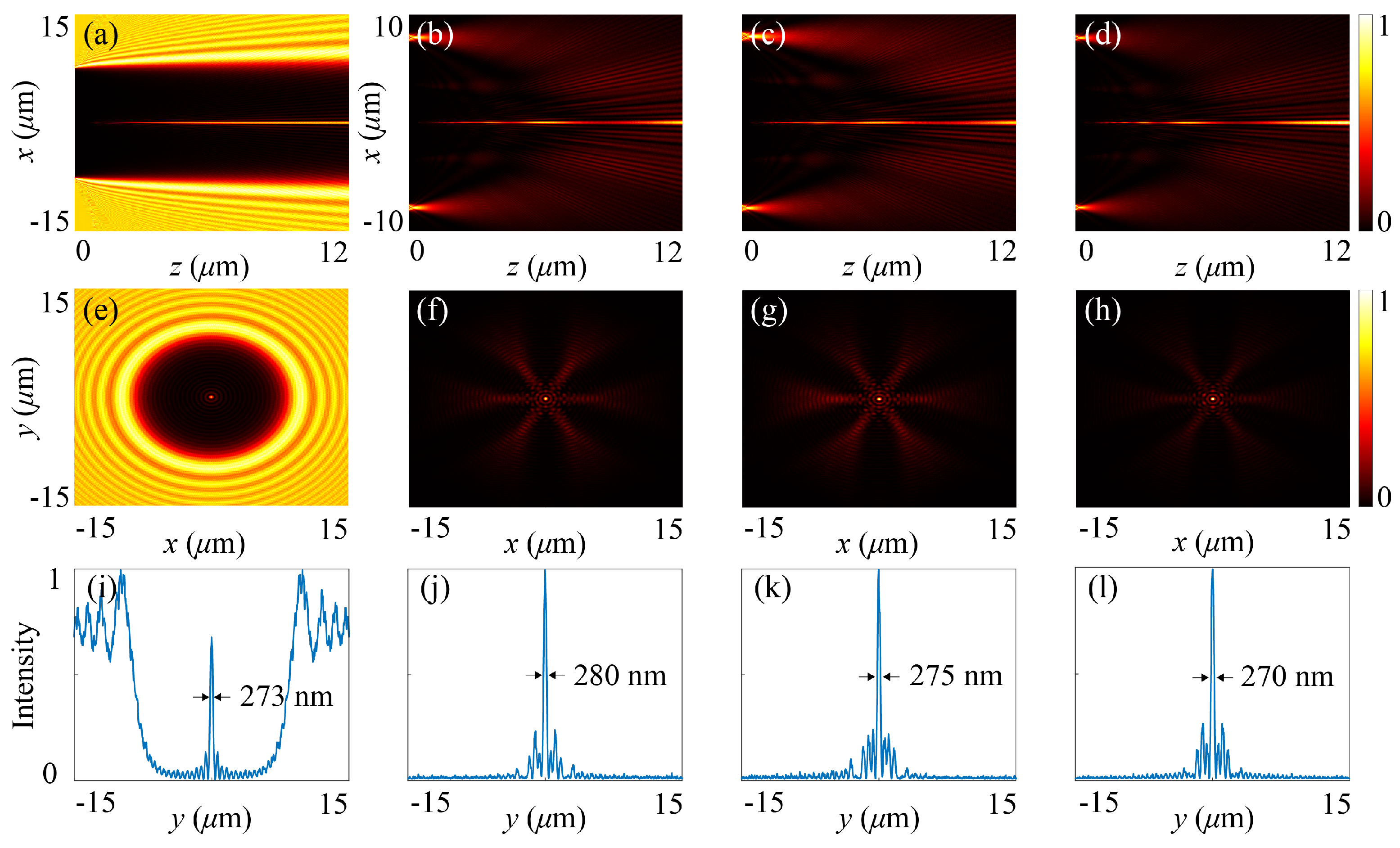
Figure 2a,e,i.
Figure 2a showcases the propagation dynamics, manifested by its intensity distribution in the
x-
z plane, whereas
Figure 2e depicts its transverse intensity distribution at a propagation distance of
m. These simulations indicate that a subwavelength light needle (nondiffracting light beam) with its full width at half maximum (FWHM) measured as 273 nm (indicated in the intensity profile in
Figure 2i) is successfully achieved. This suggests that the resultant high-spatial-frequency wave vectors distribute in phase in the reciprocal space. However, this single circular sharp-edge aperture produces a strong background field originating from the zero-order diffraction that severely limits the effective field of view (see
Figure 2e). To quantify efficiency of the generated subwavelength main lobe, we define a ratio between the peak intensities of the on-axis main lobe (
) and the strongest off-axis side lobe (
), written as
. This quantified expression shows that, if
, the off-axis background field (side lobes) becomes dominant; if
, the on-axis subwavelength light field becomes dominant. With this definition, we measure the ratio for the studied case depicted in
Figure 2a,e,i as
, suggesting a dominant background field in the far field.
Then we study how the introduced random slit motifs influence the background field. The three columns on the right-hand side of
Figure 2 display the diffractive behaviors of light wave after it passes through the randomized slit-motif apertures, with three different randomness strengths
,
, and
, corresponding to the results in
Figure 2b,
Figure 2c, and
Figure 2d, respectively. These three panels depict the intensity distributions in the
x-
z plane, revealing a continuous light needle along the on-axis positions. Compared to the result in
Figure 2a, the randomly perturbed slit motifs are able to substantially reduce the background light field, as can be judged from their transverse intensity distributions in
Figure 2f,
Figure 2g and
Figure 2h, respectively. Such a suppressed background light field is caused by the destructive interference of the zero-order diffractive waves. Specifically, the randomly modulated sharp-edge structure considerably reduces the phase coherence of the low-spatial-frequency components while maintaining the in-phase distribution of the high-spatial-frequency wave vectors in the reciprocal space. As a consequence, we observe a subwavelength light field located at the on-axis positions, propagating along the
z direction without significant broadening. As for the slight oscillation of light intensity with propagation distance, it is caused by random pattern of the sharp-edge structure breaking the cylindrically symmetric distribution of the high-spatial-frequency wavevectors. The generated subwavelength nondiffracting light field exhibits high contrast, manifested by a high value of the generation efficiency
, measured as
, 1.67, 1.89, respectively. Interestingly, as the randomness strength increases, the value of
shows a weak upward trend. Of course, from an energy perspective, most of the incident energy is blocked, resulting in lower energy in the focal region. In this regard, we believe that increasing the transmitting duty cycle of sharp-edge structure and altering the transmittance of the blocked area could potentially improve the energy efficiency. Moreover, to characterize the subwavelength feature size of the on-axis focal spot, we plot the one-dimensional intensity profiles of the light fields at the distance of
m, along the
y coordinate at
, with results shown in
Figure 2j–l, corresponding to the three different randomness strengths. The FWHM values of the main lobe are measured as 280 nm, 275 nm, and 270 nm, respectively, all below the diffraction limit (
). Using this designed technique, we are able to break the tradeoff between the central subwavelength light spot and the off-axis background field. Here, we not only eliminate the background field by means of the randomized slit-motif structure but also generate the nondiffracting light beam with feature size comparable to that shown in
Figure 2i.
To further verify the robustness of the proposed slit-motif sharp-edge aperture, we perform different independent simulations with the randomness strength of
while keeping other parameters unchanged.
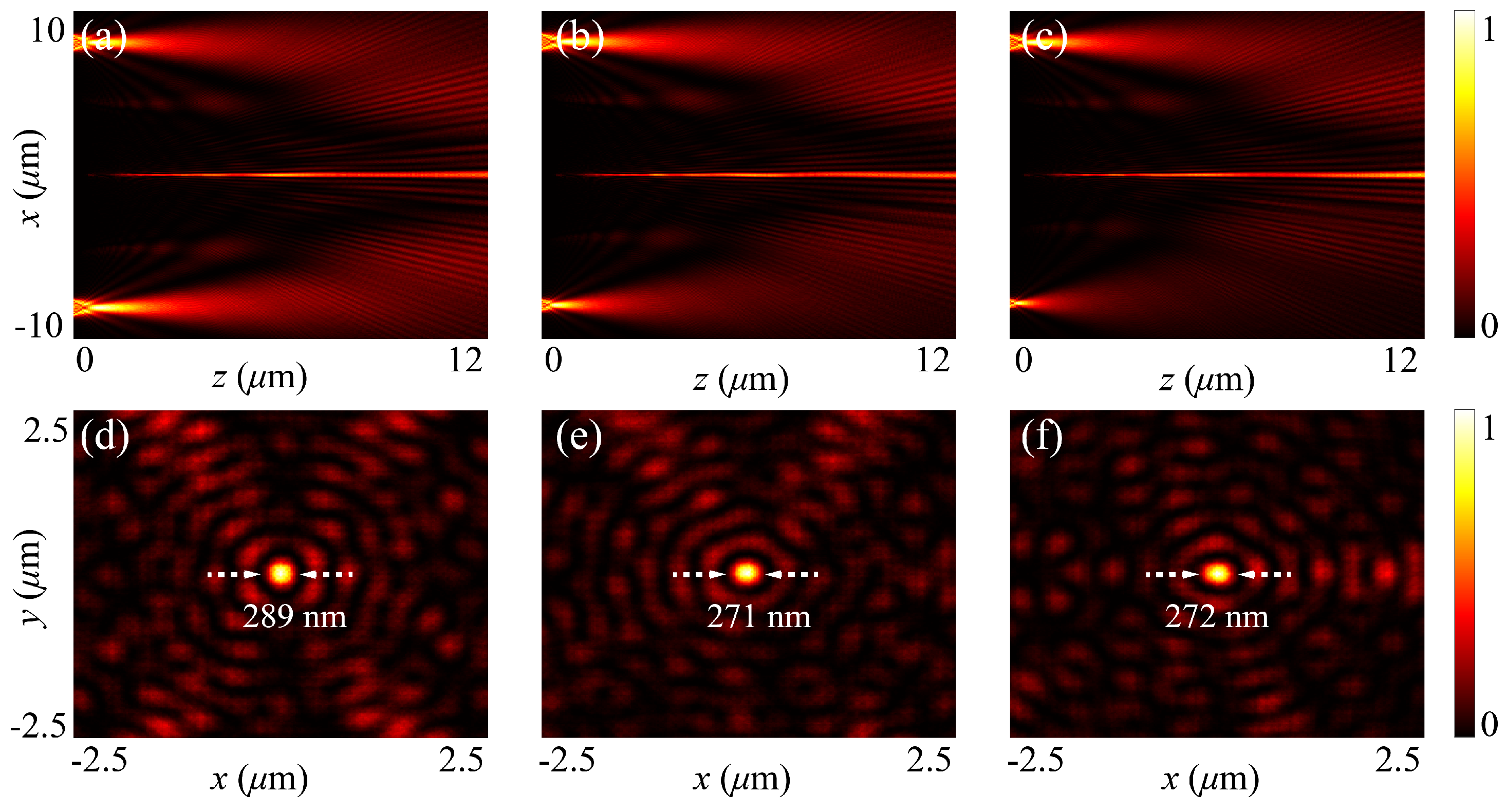
Figure 3 illustrates the simulated results for three different cases of random slit motifs. In these three random sharp-edge apertures, the maximum slit widths (in
m) of the individual slit motifs are randomly obtained as
[0.8732, 1.0405, 0.7348, 0.7734, 1.2383, 0.9794], [1.2075, 0.9984, 0.9563, 0.7837, 0.9412, 0.8783], and [1.2363, 0.6417, 0.9170, 0.7480, 1.1222, 0.9548], respectively (here
). As shown in
Figure 3a–c, all these three randomized configurations consistently produce the subwavelength nondiffracting Bessel-like beams along the on-axis positions, with weak side lobes accompanied. The overall beam morphology and intensity distribution near the on-axis region remain nearly identical, indicating that the subwavelength confinement of the light field is insensitive to the specific form of the random perturbations. Meanwhile, the background field is effectively suppressed in all these cases, due to the random-induced destructive interference effect among the zero-order diffractive components. At a propagation distance of
m, quantitative analysis of the transverse intensity profiles (see
Figure 3d–f) yields FWHM values of 289 nm, 271 nm, and 272 nm for the three representative configurations, all well below the diffraction limit. In addition, we also calculate the spot size (FWHM value) for different propagation distances. For example, in the case of
and
, the calculated results are shown in
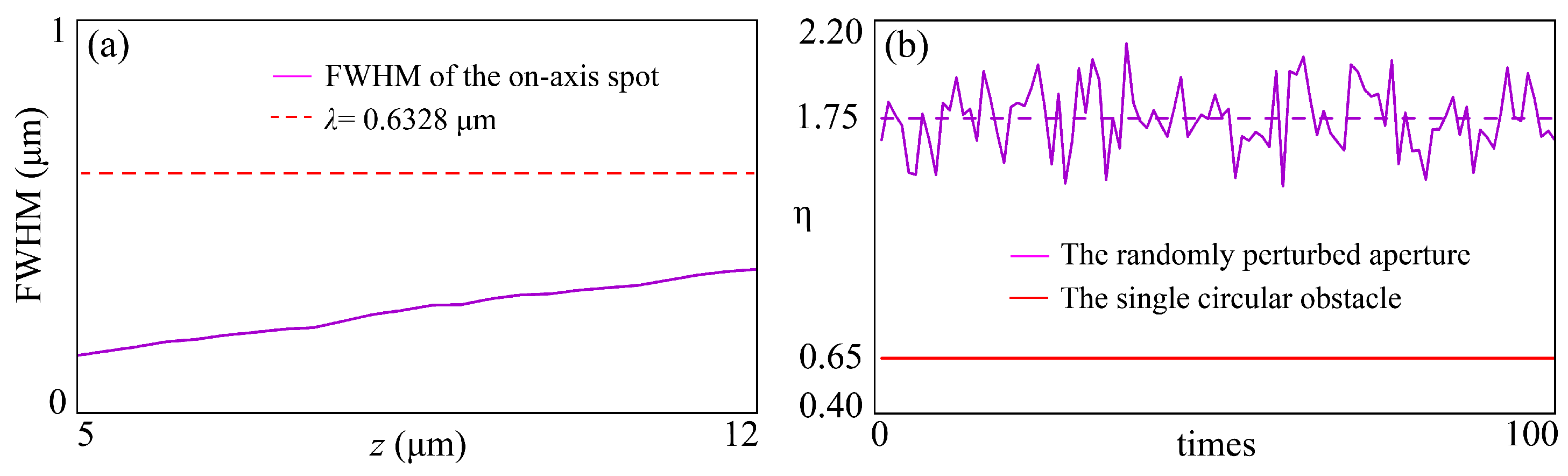
Figure 4a. It can indeed be seen that the focused spot sizes are all at the subwavelength scale, and there is no obvious broadening. The robustness of these diffractive behaviors can be understood as follows: The circular sharp edge (the basic obstacle) in all these randomly modulated structures coherently excites the high-spatial-frequency diffractive components with their wave vector distributed in phase, leading to constructive interference along the optical axis. By contrast, the randomized slit motifs (regardless of the structure involved) introduce phase perturbations among the low-spatial-frequency diffractive components, which gives rise to destructive interference effect in the off-axis region.
Figure 4b further quantifies the high-contrast subwavelength light field. For comparison, the red curve depicts the generation efficiency of the subwavelength light field obtained by the sharp-edge circular disc (without random modulation), showing a much lower efficiency due to the pronounced sidelobes (the background light field). By contrast, statistical analysis over 100 independently simulations for the randomized apertures (
,
) shows that the focusing efficiency remains much higher than 1, indicating the generated high-contrast subwavelength main lobe. Due to the random effect, we observe that the efficiency curve exhibits slight fluctuation around an average value of
. The efficiency curve obtained by the 100-time simulation confirms that the random-induced destructive interference among the low-spatial-frequency diffractive components is robust and reproducible, suggesting a novel mechanism for achieving the high-contrast subwavelength nondiffracting light beam.
To confirm the universality of the proposed mechanism, we investigate the focusing performance of the randomized petal-like apertures with different numbers of the slit motifs, where the geometric symmetry is intentionally broken in the azimuthal direction. The random perturbation with randomness strength set as
is applied to the pentagonal (
) and heptagonal (
) slit-motif apertures, as illustrated in
Figure 1e and
Figure 1f, respectively. Owing to the reduced rotational symmetry, both the sharp-edge configurations generate well-defined subwavelength nondiffracting light beams with high contrast, measured as
and
; see
Figure 5a–c and
Figure 5d–f for the two configurations, respectively.
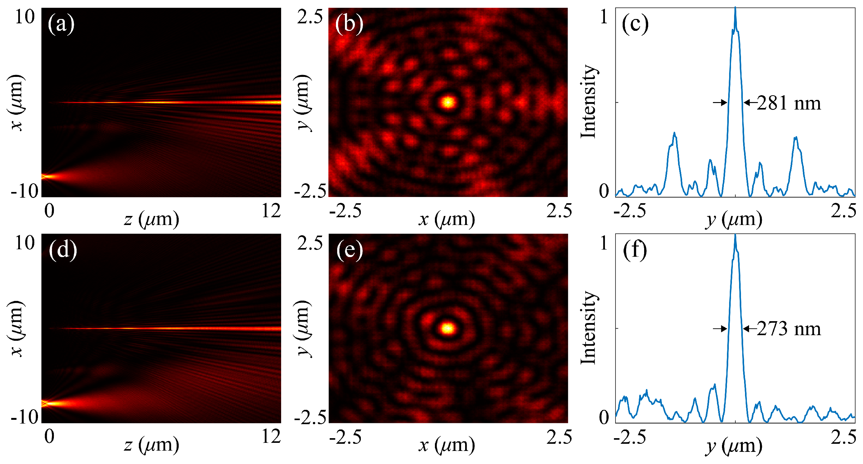
Figure 5a,d illustrate that the resultant light beams remain highly stable, exhibiting nearly nondiffracting propagation along distance. As shown in
Figure 5b,e the broken symmetry of the slit-motif sharp-edge aperture causes only slight distortions in the off-axis intensity profiles, while the central bright core remains tightly confined, preserving its intensity profile along the propagation distance. Quantitative analysis reveals the FWHM values of 281 nm and 273 nm for the pentagonal and heptagonal cases, respectively, as indicated in their intensity profiles in
Figure 5c,f. Consequently, the proposed working principle exhibits strong tolerance to both the structural randomness and the number of the slit motifs.
Finally, we examine the propagation dynamics of a vortex light beam when it is diffracted by the randomly modulated slit-motif aperture. In this case, we modify the incident light field as
, where
denotes the initial width of the vortex light beam and
m represents the topological charge. It is no longer an incident plane wave but a structured light beam with helical wavefront and a hollow beam profile described by the Laguerre–Gaussian (LG) function. For simplicity, here we study the case of
. Hence, the initial condition therefore becomes
. In the simulation, we consider the six-fold slit-motif aperture (as shown in
Figure 1d) as illustrations, with randomness strength set as
, while keeping other structural parameters unchanged. The width of the LG profile is chosen as
m. With these settings, we obtain the results, as depicted in
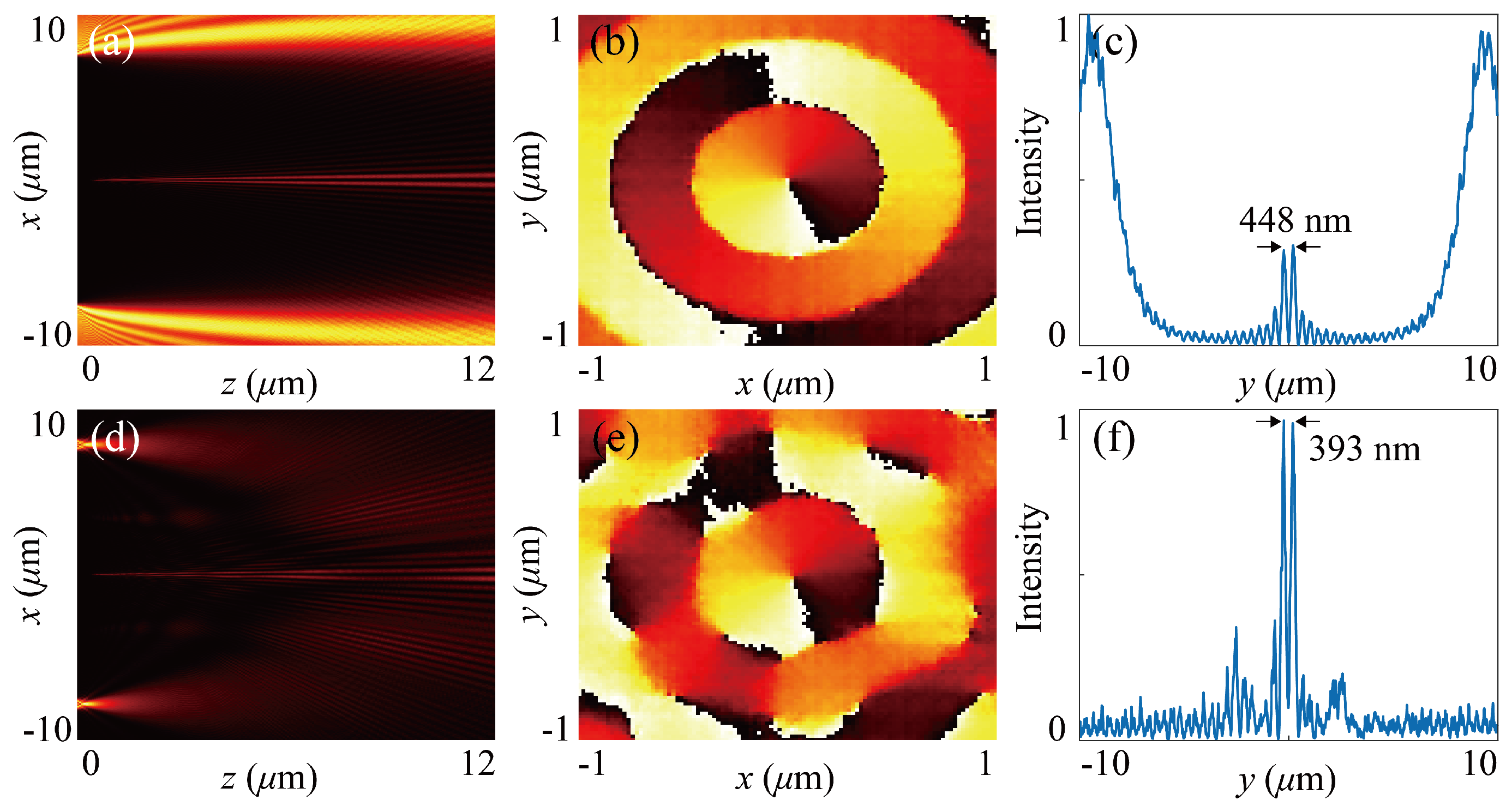
Figure 6. As a reference, we first investigate the sharp-edge diffraction by the single circular obstacle, with results shown in
Figure 6a–c, demonstrating the intensity distribution in the
x-
z plane, transverse phase distribution at
m, and the one-dimensional intensity profile at
m, respectively. It is evident that a subwavelength nondiffracting vortex light beam can be generated in the far field. The subwavelength feature size is characterized by its peak-to-peak distance of the on-axis vortex field, as indicated as 448 nm in
Figure 6c. It means that the designed sharp-edge aperture is able to recover the initial topological wavefront in the far field (see
Figure 6b). However, the resultant efficiency is relatively low, as most of the energy goes to the side lobes. Such a low-contrast subwavelength vortex beam becomes uncompetitive in terms of various applicable fields. By contrast, the sharp-edge diffraction of the randomly modulated structure considerably reduces the background field and enhance the contrast, as shown in
Figure 6d–f. In this case, we obtain an obvious increase of the generation efficiency while maintaining the subwavelength feature size, as indicated in
Figure 6f. Even though the sharp-edge aperture is randomly perturbed, the far-field light field exhibits well-defined helical wavefront (see
Figure 6e), identical to that obtained from the circular aperture.