Communication

Highly Sensitive Light Guide Sensor for Multilocation and Multimodal Deformation Decoupling Using Flexible OLED

Integrated Engineering, Department of Chemical Engineering, Kyung Hee University, Yongin-si 17104, Republic of Korea
*
Author to whom correspondence should be addressed.
These authors contributed equally to this work.
Photonics 2025, 12(9), 909; https://doi.org/10.3390/photonics12090909
Submission received: 15 August 2025 / Revised: 4 September 2025 / Accepted: 9 September 2025 / Published: 10 September 2025
(This article belongs to the Special Issue Advances in Optical Sensors and Applications)

Abstract

This work proposes a highly sensitive optical sensor system that compensates for joint fragility by combining a flexible organic light-emitting diode (FOLED) with a stretchable light guide, and its performance was systematically evaluated. The developed sensor, leveraging the high flexibility of OLEDs, was capable of detecting mechanical deformations in various positions and forms in real time and could distinguish up to seven independent signals without electromagnetic interference. Under repeated 50% tensile strain, the device sustained 130,000 cycles, and during the 75° bending test, all three configurations—single line, serpentine, and serpentine with bump—exhibited stable performance for a minimum of 80,000 cycles. The sensor system developed in this study holds promise for future applications in wearable electronics and robotics.

1. Introduction

Proprioception in animals refers to the ability to perceive the position and condition of their body parts through various sensory organs [1]. In particular, animals can perceive the condition of their bodies and precisely control complex movements even without vision, by detecting vibrations caused by deformation and mechanical stress through not only tactile organs beneath the skin but also sensory receptors located in muscles and tendons [2].
Most current robotic systems rely on cameras and sensors that are primarily concentrated around the robot’s joints or central body to perceive and control their posture and the external environment [3,4]. However, for more precise and flexible control, it is necessary to distribute sensors throughout the entire robot structure and to implement a system capable of simultaneously collecting mechanical signals from various locations [5,6,7]. Stretchable sensors developed for this purpose operate based on electrical signals and are generally designed to detect deformation in specific areas by monitoring changes in resistance, capacitance, voltage, or current [8,9,10]. However, such electrical sensors respond only to specific stimuli and have limitations in simultaneously detecting or distinguishing multiple combined stimuli [11,12,13]. In addition, they suffer from reduced response speed due to the resistance–capacitance delay [14,15].
In contrast, optical sensors can provide rapid and information-dense signals by leveraging various parameters such as light intensity, phase, polarization, and wavelength, and they are unaffected by electromagnetic interference [16]. With simple circuit designs, optical sensors can achieve fast response times and are regarded as an effective alternative to traditional electrical sensors [17,18,19]. These sensors accurately track bodily states by measuring optical losses caused by strain, based on phenomena such as fiber deformation, fiber Bragg gratings, or frustrated total internal reflection [20]. The stretchable light guide can quantitatively measure its own tensile strain based on Beer’s law, enhancing both the scalability and accuracy of the sensor [21].
This research proposes the use of a flexible organic light-emitting diode (FOLED) as a light source to overcome the limitations associated with rigid LED sources typically used in traditional optical guide sensors—specifically, the fragile and non-flexible connection points between the light source and the optical waveguide. By utilizing the inherent flexibility of OLEDs, the study explores the feasibility of vibration sensing [22,23]. Such sensors can simultaneously detect a variety of physical signals, including not only simple deformations but also surface vibrations and dynamic motion patterns. Additionally, changes in light intensity caused by vibration and deformation can be measured independently of each other. Furthermore, the system integrates three stretchable light guide sensors to detect up to seven distinct signals, providing a foundation for real-time multi-point and multi-mode deformation sensing. This FOLED-based optical sensing technology is anticipated to serve as a promising platform for enabling advanced sensory functions and precise control in robotics.

2. Materials and Methods

The CPI employed as the substrate was Kolon’s CPI™ (KOLON Industries, Seoul, Republic of Korea). Poly(3,4-ethylenedioxythiophene) polystyrene sulfonate (PEDOT:PSS) served as the transparent electrode and was obtained as Clevios™ PH 1000 (Heraeus, Hanau, Germany). 1,1-Bis[(di-4-tolylamino)phenyl]cyclohexane (TAPC) and 4,4′,4″-tris [2-naphthyl(phenyl)amino]triphenylamine (2-TNATA) were used as the hole injection layer (HIL). The hole transporting layer (HTL) was composed of 4,4′,4″-tris(carbazol-9-yl)triphenylamine (TCTA) and N,N′-bis(naphthalen-1-yl)-N,N′-bis(phenyl)benzidine (NPB). For the red and blue devices, the emissive layer was deposited using a host–dopant system: N,N′-dicarbazolyl-3,5-benzene (mCP) and 9-(1-naphthyl)-10-(2-naphthyl)anthracene (α,β-ADN) served as the host materials, while bis(1-phenylisoquinoline)(acetylacetonate)iridium(III) (Ir(piq)2acac) and N1,N6-bis(2,4-dimethylphenyl)pyrene-1,6-diamine (3Me-1Bu-TPPDA) were used as dopants. For the green device, tris(8-hydroxyquinolinato)aluminum (Alq3) was employed as both the emissive and electron-transporting layer (ETL). 1,3,5-Tri(m-pyridin-3-ylphenyl)benzene (TmPyPB) was applied as the ETL in the red device. Lithium fluoride (LiF) served as the electron injection layer (EIL), while aluminum (Al) was used as the cathode. All organic materials were purchased from Lumtec (New Taipei, Taiwan) and were used without further purification. The fabricated FOLED devices in red, green, and blue colors have the following structures. Red (R): CPI/PEDOT:PSS/TAPC (30 nm)/TCTA (10 nm)/mCP: 10 wt% Ir (piq)2acac (80 nm)/TmPyPB (30 nm)/LiF (1 nm)/Al (200 nm), Green (G): CPI/PEDOT:PSS/2-TNATA (60 nm)/NPB (15 nm)/Alq3 (120 nm)/LiF (1 nm)/Al (200 nm), Blue (B): CPI/PEDOT:PSS/2-TNATA (60 nm)/NPB (15 nm)/α,β-ADN: 4 wt% 3Me-1Bu-TPPDA (120 nm)/Alq3 (15 nm)/LiF (1 nm)/Al (200 nm). PEDOT:PSS was spin-coated at 4000 rpm for 60 s and subsequently annealed at 140 °C for 20 min. After cooling to room temperature, the prepared substrates were transferred to a thermal evaporation chamber. The remaining layers were sequentially deposited in the chamber under a vacuum of 1.0 × 10⁻⁶ torr at a rate of 1 Å/s. The fabricated device was prepared without encapsulation. The lack of encapsulation can lead to degradation. Therefore, instead of encapsulation, all measurements were carried out under a light-shielded box with a controlled N2 environment. Moreover, the FOLED device was connected to a light collector lens and a conical optical fiber, which provided additional protection against moisture and oxygen that could cause degradation. Consequently, the device exhibited stable operation during the measurements. The fabricated device has dimensions of 3.5 × 3.5 cm2 and consists of five individual cells. The images of the fabricated RGB FOLED devices are shown in Figure 1.
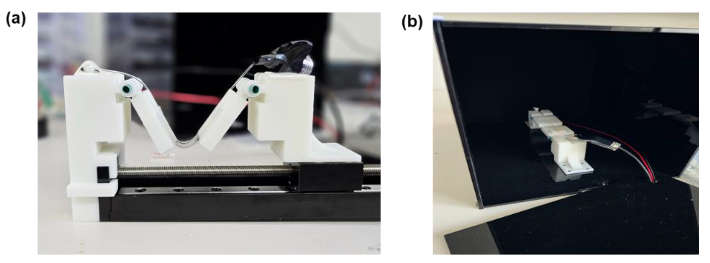
To consistently measure the mechanical properties of the deformation sensor, such as bending and tensile strain, the sensor structure was designed to be compatible with a linear stage. This setup enabled the precise and repetitive execution of bending and stretching tests. The stage module was produced via 3D printing and used in the sensor’s cyclic durability tests (Figure 2a). Additionally, to eliminate interference from external illumination, particularly changes in sunlight entering through windows, the experiments were performed under controlled light-blocking conditions. To control the experimental environment, a light-shielded box made of polyacrylate material was built, inside of which bending and stretching modules were installed to minimize external environmental effects and ensure stable testing (Figure 2b).

3. Results and Discussion

3.1. Structure of the FOLEDs and Optical Fiber Sensor System

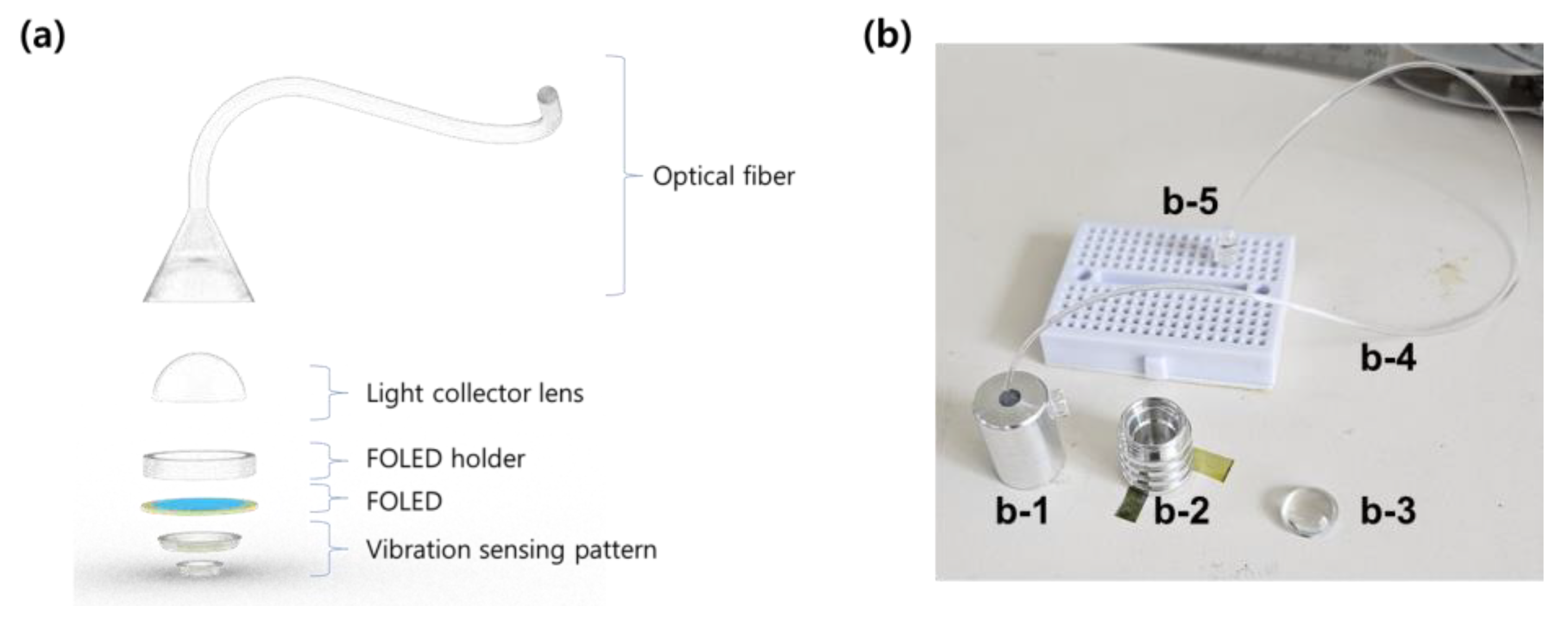
When the light source of a conventional LED sensor is simply replaced with an FOLED, vibration detection was found to be challenging, particularly due to the absence of a condenser lens, which restricted the efficient coupling of light emitted from the OLED into the optical fiber. To address this limitation, in the present study, the FOLED was coupled with a light collector lens and a conical optical taper connected to the optical fiber. This configuration enables effective collection of light emitted from the FOLED and minimizes optical losses during transmission into the fiber [24]. A half-ball lens has often been employed as an external light-extraction structure, and its effectiveness has been demonstrated by achieving OLEDs with external quantum efficiencies exceeding 50% [25]. The conical optical taper was designed for ease of fabrication and realized using 3D printing. A reflective cover was placed over the sensor surface to minimize interference from external light. A schematic representation of this setup is given in Figure 3a, and a photograph of the actual sensor is shown in Figure 3b. The optical fiber used was a transparent polymethyl methacrylate (PMMA) fiber with a diameter of 3 mm and an optical loss of ~650 dB/km. Since the actual fiber length employed was 1 m, the resultant optical attenuation was about 0.65 dB (≈14% loss), a level that does not compromise sensor operation. Quantitative experiments on light outcoupling efficiency arising from the use of the light collector lens and optical losses at the interface between the light source and optical fiber will be performed in future work.
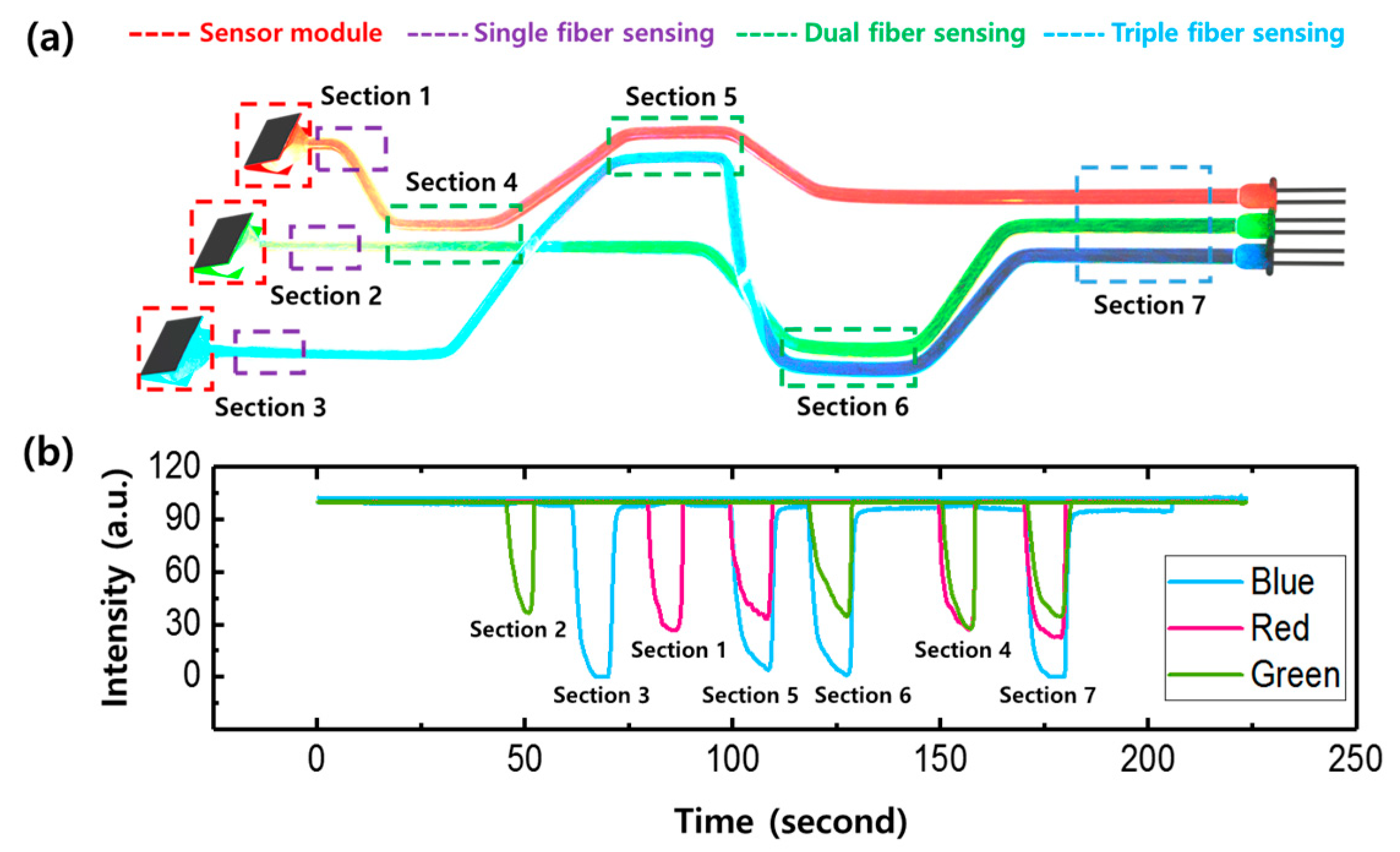
The FOLED was fabricated to replace the LED light source in the conventional sensor. It was constructed as a multilayer structure on a flexible CPI substrate and operated by directly coupling its light output into an optical fiber. The schematic of the fabricated device is shown in Figure 4a, and the detailed device structure is described in the experimental section. The performance of the fabricated RGB FOLED devices is summarized in Figures S1–S3 and Table S1. For the red device, the current efficiency (CE) was 2.79 cd/A, and the external quantum efficiency (EQE) was 3.90%. The green device exhibited a CE of 1.18 cd/A and an EQE of 1.19%, while the blue device showed a CE of 3.24 cd/A and an EQE of 1.81%. Overall, these three devices showed lower efficiencies and higher driving voltages compared with conventional OLEDs fabricated on rigid glass substrates. However, their brightness remains sufficient for application as sensor light sources, and with further optimization of the device architecture and fabrication procedures, the sensor performance can be further enhanced. The maximum electroluminescence (EL) wavelengths measured from the fabricated devices were 465, 530, and 627 nm, corresponding to blue, green, and red colors, as confirmed in Figure 4b. Figure 4c shows a photograph of the operational FOLED-optical fiber sensor system. Red, green, and blue light propagate through the optical fibers, visually demonstrating the sensor’s flexibility and the sensing characteristics along the optical fiber paths. A schematic representation of this configuration is provided in Figure 5a. Each optical fiber connected to the color-specific sensors was terminated with a photodiode, which converted the collected vibrations and light intensity variations into electrical signals subsequently measured with an oscilloscope. Sections 1–3 permitted single sensing, Sections 4–6 provided dual sensing, and Section 7 enabled triple sensing of all RGB channels. Under no deformation, the device preserved a stable reference signal; however, manual stretching of the optical fiber in the single, dual, or triple zones caused pronounced changes in light intensity in the respective sensors. Although the applied tensile force was not quantitatively measured, the responsiveness of the system to mechanical deformation was evident. These findings indicate that the temporal separation of signal responses across the three sensors reflects the ability of the system to independently sense deformation stimuli at multiple locations and in multimodal deformation decoupling. The mechanochromic properties were found in the studies of the isomers of Alq3 [26,27]. In this experiment, no mechanochromic change of Alq3 was observed. This is because the evaluation of the sensor system relied on the mechanical deformation of the optical fiber rather than the light source itself [28]. In future work, the possibility of observing mechanochromic characteristics in Alq3 will be examined by evaluating a sensor system that employs the deformation of the FOLED device directly. Such FOLED-based optical fiber sensor systems are highly flexible and, due to their thin and lightweight structure, can be attached to various surfaces like skin, fabrics, or robotic joints for precise vibration sensing.

3.2. Physical Deformation Sensing with Stretchable Optical Fiber

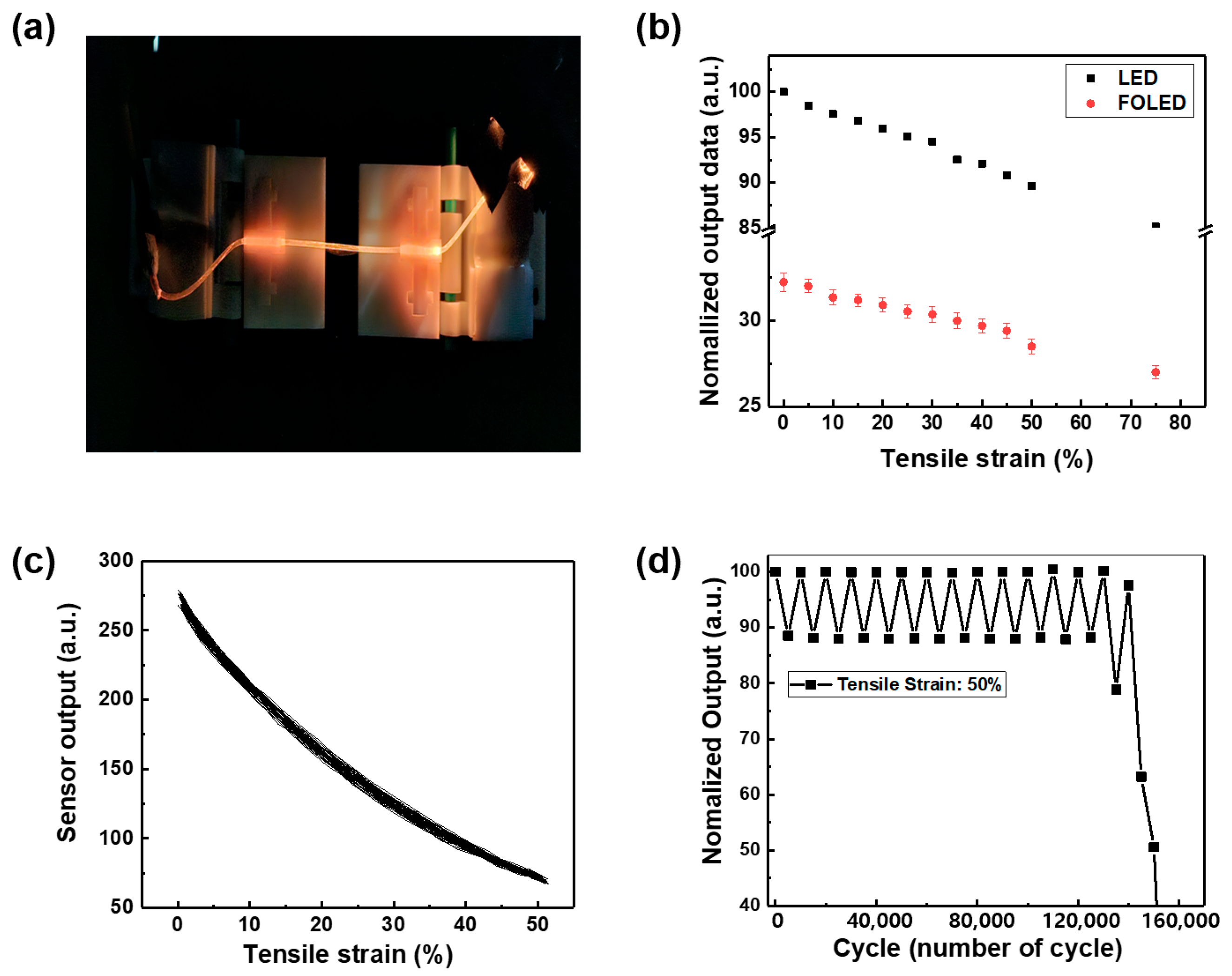
The sensitivity and stability of the actual FOLED sensor under various mechanical deformation conditions were evaluated and compared to those of an LED sensor (Figure 6a). To maintain identical optical coupling conditions during the experiments, the same lens and optical fiber used in the FOLED sensor were also employed in the LED sensor. In addition, because the stable operation of the FOLED device could influence the experimental results, it was driven in a constant-current mode to maintain a uniform luminance. This operating approach minimizes fluctuations in the driving conditions during cyclic evaluation over time, but it also has the drawback of potentially altering sensor performance during continuous operation for more than a week. To mitigate such degradation, the light-shielding box was maintained in an N2 environment, and the integration of the light collector lens and optical taper provided an encapsulation-like effect, allowing the device to remain stably operational during the evaluation. For this test, the yellow FOLED device was fabricated with the following configuration: CPI/PEDOT:PSS/PDY132 (40 nm)/Alq3 (15 nm)/LiF (1 nm)/Al (200 nm). PDY132 is a well-known emitter called super yellow (SY). A solution of PDY132 (Merck, Darmstadt, Germany) was prepared at a concentration of 4.5 mg in 1 mL of toluene and spin-coated instead of being vacuum-deposited. The film was then annealed at 130 °C for 30 min. The remaining fabrication steps were carried out as previously described in Section 2.
Figure 6b presents a comparison of the output changes under tensile strain between FOLED-based optical sensors and conventional LED-based sensors. While both light sources show a tendency for output to decrease as the strain increases, the FOLED sensor demonstrates a more stable response than the LED. Although the initial output intensity of the FOLED was measured as relatively lower than that of the LED, this is attributed to differences in light source efficiency and does not reflect the intrinsic sensitivity of the sensor.
Figure 6c shows the results of a cyclic stretching test conducted under a 50% tensile strain condition. This strain level reflects the typical deformation encountered in practical applications such as wearable sensors, soft electronics, and sensors attached to robotic joints. Therefore, it was selected as a suitable condition to evaluate the reliability and reproducibility of the sensor in realistic conditions [29,30]. The experimental results show that the sensor output remains consistent throughout the stretching and releasing cycles, with minimal hysteresis observed. This indicates that the sensor maintains output stability even under high-strain conditions and can respond to repeated physical stimuli with high accuracy.
Figure 6d presents the results of a cyclic stretching test in which the sensor was subjected to 150,000 repetitions under 50% tensile strain. Initially, the output signal remained stable; however, after approximately 130,000 cycles, the baseline began to fluctuate, and a sharp decrease in output was observed. It is considered that the necking phenomenon occurred in certain sections of the optical fiber, leading to a local reduction in cross-sectional area and an increase in optical loss due to stress concentration [31]. Necking indicates that the material has reached its mechanical limit due to repeated fatigue, ultimately causing the output to completely fail at around 150,000 cycles. Nevertheless, this level of cyclic durability is considered sufficient for application in highly reliable sensor systems.
Bending tests were performed on the produced sensors featuring three configurations: single line, serpentine, and serpentine with bump. Figure 7a presents a diagram of the test procedure. Such geometric designs affect the mechanical flexibility as well as the detection sensitivity under bending conditions. The single-line structure simulates conditions when attached to flat or slightly curved surfaces, such as sensor environments on the back of the hand, forearm, or other static mounting locations [32]. The serpentine design simulates sensor placement on areas subject to frequent flexing, like joints including the wrist, elbow, and knee, which undergo repetitive bending motions. This structure is frequently evaluated for practical application in wearable electronic devices. In the actual test, the serpentine area was restricted to approximately 10 × 10 cm2 [33]. The serpentine-with-bump structure simulates environments requiring complex detection beyond simple deformation, including contact, vibration, and changes in surface pressure. Bumps enhance sensitivity to vibration and touch stimuli by inducing localized structural deformation, thereby improving overall sensor responsiveness [34]. In the experiment, the bump used was a round stainless steel rod measuring 12 cm in length, with an inner diameter of 0.7 cm, and weighing approximately 100 g.
Figure 7b illustrates the variation in sensor output with bending angles ranging from 0° to 100° and compares the response characteristics of different structures. The conventional LED sensor exhibited almost no change in output over the entire bending range. By contrast, the FOLED sensor exhibited progressively enhanced sensitivity depending on the structural design: single line, serpentine, and serpentine with bump. In particular, the serpentine-with-bump structure revealed a substantial output reduction at bending angles exceeding 30°, highlighting its pronounced angle-dependent sensitivity. The lack of output variation despite changes in bending angle implies that the LED sensor is incapable of recognizing mechanical deformation induced by bending, whereas the FOLED sensor is more suitable for sensing applications because it can detect subtle mechanical changes associated with angle variations. A forthcoming study will present the experimental findings on the signal-to-noise ratio (SNR), providing a quantitative analysis based on systematic variations in the experimental conditions.
Figure 7c presents the results of cyclic bending tests at a 75° bending angle, comparing the long-term durability and sensitivity characteristics of each structure. This angle was selected based on the actual range of motion of human finger joints to reflect a biomimetic environment under various wearing conditions. The metacarpophalangeal (MCP) joint links the palm to the fingers and flexes between roughly 0° and 90°. The proximal interphalangeal (PIP) joint can bend about 100–120°, and the distal interphalangeal (DIP) joint has a flexion range of approximately 70–90° [35,36]. Therefore, 75° corresponds to the average bending range of the MCP and DIP joints and is considered an appropriate condition that effectively represents typical mechanical stimuli encountered during daily finger movements or wearable sensor applications. Accordingly, repeated 75° bending cycle tests were performed on the single-line, serpentine, and serpentine-with-bump configurations to assess their endurance and dependability in practical application environments.
All structures initially exhibited stable output; however, the single-line structure showed a sharp decline in output after 100,000 cycles, whereas the serpentine and serpentine-with-bump structures saw a steep reduction in output around 80,000 cycles. This is believed to result from repeated mechanical stress accumulating at structurally high-curvature regions. Furthermore, distinct differences in output amplitude were observed depending on the structure: the single-line design showed an output around 10 a.u., whereas the serpentine and serpentine-with-bump structures exhibited much higher amplitudes of approximately 50 a.u. and 90 a.u., respectively. This reflects the structural characteristics of serpentine-based designs, which induce greater changes in optical path length and optical loss during bending, resulting in enhanced sensitivity.

4. Conclusions

This research presents the development and fabrication of a new type of stretchable optical sensor utilizing a FOLED as the illumination source. Through diverse optical fiber coupling configurations, the sensor supports multilocation and multimodal deformation detection. The use of FOLEDs improved surface-vibration sensing performance over traditional LED-based sensors. In repeated tensile tests, the sensor endured up to 130,000 cycles, and in 75° bending tests, all three structures—single line, serpentine, and serpentine with bump—sustained at least 80,000 cycles. This level of cyclic durability is considered sufficient for application in high-reliability sensor systems. Based on these results, the next phase of research will involve bending tests focused on the light source itself to evaluate its mechanical durability and sensitivity at the source level.

Supplementary Materials

The following supporting information can be downloaded at: https://www.mdpi.com/article/10.3390/photonics12090909/s1, Figure S1. EL characteristics of red FOLED (a) J-V-L curve, (b) CE versus current density, (c) PE versus current density, and (d) EQE versus current density.; Figure S2. EL characteristics of green FOLED (a) J-V-L curve, (b) CE versus current density, (c) PE versus current density, and (d) EQE versus current density.; Figure S3. EL characteristics of blue FOLED (a) J-V-L curve, (b) CE versus current density, (c) PE versus current density, and (d) EQE versus current density.; Table S1. EL performances of the RGB FOLED devices.

Author Contributions

Conceptualization, H.S.A. and J.P.; methodology, H.L. and H.S.A.; validation, H.S.A.; formal analysis, H.S.A.; investigation, H.L. and H.S.A.; resources, J.P.; writing—original draft preparation, H.L. and J.P.; writing—review and editing, H.L. and J.P.; visualization, H.L. and H.S.A.; supervision, J.P.; project administration, J.P.; funding acquisition, J.P. All authors have read and agreed to the published version of the manuscript.

Funding

This work was partly supported by the GRRC program of Gyeonggi province [(GRRCKYUNGHEE2023-B01), Development of ultra-fine process materials based on the sub-nanometer class for the next-generation semiconductors]. This research was supported by the Basic Science Research Program through the National Research Foundation of Korea (NRF), funded by the Ministry of Education (RS-2020-NR049601).

Institutional Review Board Statement

Not applicable.

Informed Consent Statement

Not applicable.

Data Availability Statement

Data are contained within the article.

Conflicts of Interest

The authors declare no conflicts of interest.

References

  1. O’Rahilly, R.; Müller, F.; Carpenter, S.; Swenson, R.S. Chapter 3: The nervous system. In Basic Human Anatomy; Swenson, R., Ed.; Dartmouth Medical School: Hanover, NH, USA, 2008. [Google Scholar]
  2. Chortos, A.; Liu, J.; Bao, Z. Pursuing prosthetic electronic skin. Nat. Mater. 2016, 15, 937–950. [Google Scholar] [CrossRef]
  3. Dahiya, R.S.; Metta, G.; Valle, M.; Sandini, G. Tactile sensing—From humans to humanoids. IEEE Trans. Robot. 2010, 26, 1–20. [Google Scholar] [CrossRef]
  4. Muth, J.T.; Vogt, D.M.; Truby, R.L.; Mengüç, Y.; Kolesky, D.B.; Wood, R.J.; Lewis, J.A. Embedded 3D printing of strain sensors within highly stretchable elastomers. Adv. Mater. 2014, 26, 6307–6312. [Google Scholar] [CrossRef] [PubMed]
  5. Wehner, M.; Truby, R.L.; Fitzgerald, D.J.; Mosadegh, B.; Whitesides, G.M.; Lewis, J.A.; Wood, R.J. An integrated design and fabrication strategy for entirely soft, autonomous robots. Nature 2016, 536, 451–455. [Google Scholar] [CrossRef]
  6. White, E.L.; Yuen, M.C.; Kramer, R.K. Distributed sensing in capacitive conductive composites. In Proceedings of the IEEE Sensors, Glasgow, UK, 29 October–1 November 2017; IEEE: New York, NY, USA, 2017; pp. 1–3. [Google Scholar] [CrossRef]
  7. Anderson, I.A.; Gisby, T.A.; McKay, T.G.; O’Brien, B.M.; Calius, E.P. Multifunctional dielectric elastomer artificial muscles for soft and smart machines. J. Appl. Phys. 2012, 112, 041101. [Google Scholar] [CrossRef]
  8. Case, J.C.; White, E.L.; Kramer, R.K. Sensor enabled closed-loop bending control of soft beams. Smart Mater. Struct. 2016, 25, 045018. [Google Scholar] [CrossRef]
  9. Ozel, S.; Skorina, E.H.; Luo, M.; Tao, W.; Chen, F.; Pan, Y.; Onal, C.D. A composite soft bending actuation module with integrated curvature sensing. In Proceedings of the 2016 IEEE International Conference on Robotics and Automation (ICRA), Stockholm, Sweden, 16–21 May 2016; IEEE: New York, NY, USA, 2016; pp. 4963–4968. [Google Scholar] [CrossRef]
  10. Truby, R.L.; Wehner, M.; Grosskopf, A.K.; Vogt, D.M.; Uzel, S.G.M.; Wood, R.J.; Lewis, J.A. Soft somatosensitive actuators via embedded 3D printing. Adv. Mater. 2018, 30, 1706383. [Google Scholar] [CrossRef] [PubMed]
  11. Farrow, N.; Correll, N. A soft pneumatic actuator that can sense grasp and touch. In Proceedings of the 2015 IEEE/RSJ International Conference on Intelligent Robots and Systems (IROS), Hamburg, Germany, 28 September–2 October 2015; IEEE: New York, NY, USA, 2015; pp. 2317–2323. [Google Scholar] [CrossRef]
  12. Park, Y.L.; Majidi, C.; Kramer, R.; Bérard, P.; Wood, R.J. Hyperelastic pressure sensing with a liquid-embedded elastomer. J. Micromech. Microeng. 2010, 20, 125029. [Google Scholar] [CrossRef]
  13. O’Brien, B.; Gisby, T.; Anderson, I.A. Stretch sensors for human body motion. In Proceedings of the SPIE Electroactive Polymer Actuators and Devices, San Diego, CA, USA, 30 April 2014; SPIE: Bellingham, WA, USA, 2014; Volume 9056, p. 905618. [Google Scholar] [CrossRef]
  14. Tairych, A.; Anderson, I.A. Distributed sensing: Multiple capacitive stretch sensors on a single channel. In Proceedings of the SPIE Electroactive Polymer Actuators and Devices, Portland, OR, USA, 26–29 March 2017; SPIE: Bellingham, WA, USA, 2017; Volume 10163, p. 1016306. [Google Scholar] [CrossRef]
  15. Shahinpoor, M.; Bar-Cohen, Y.; Simpson, J.O.; Smith, J. Ionic polymer-metal composites (IPMCs) as biomimetic sensors, actuators and artificial muscles—A review. Smart Mater. Struct. 1998, 7, R15–R30. [Google Scholar] [CrossRef]
  16. Ramadan, K.S.; Sameoto, D.; Evoy, S. A review of piezoelectric polymers as functional materials for electromechanical transducers. Smart Mater. Struct. 2014, 23, 033001. [Google Scholar] [CrossRef]
  17. Ju, W.-E.; Moon, Y.-J.; Park, C.-H.; Choi, S.T. A flexible tactile-feedback touch screen using transparent ferroelectric polymer film vibrators. Smart Mater. Struct. 2014, 23, 074004. [Google Scholar] [CrossRef]
  18. Pendão, C.; Silva, I. Optical fiber sensors and sensing networks: Overview of the main principles and applications. Sensors 2022, 22, 7554. [Google Scholar] [CrossRef] [PubMed]
  19. Zhao, H.; O’Brien, K.; Li, S.; Shepherd, R.F. Optoelectronically innervated soft prosthetic hand via stretchable optical waveguides. Sci. Robot. 2016, 1, eaai7529. [Google Scholar] [CrossRef]
  20. Harnett, C.K.; Zhao, H.; Shepherd, R.F. Stretchable optical fibers: Threads for strain-sensitive textiles. Adv. Mater. Technol. 2017, 2, 1700087. [Google Scholar] [CrossRef]
  21. Guo, J.; Liu, X.; Jiang, N.; Yetisen, A.K.; Yuk, H.; Yang, C.; Khademhosseini, A.; Zhao, X.; Yun, S.-H. Highly stretchable, strain sensing hydrogel optical fibers. Adv. Mater. 2016, 28, 10244–10249. [Google Scholar] [CrossRef] [PubMed]
  22. Kim, C.; Bae, K.S.; Kim, G.; Lee, D.-Y.; Moon, G.; Yang, D.; Lee, H.; An, J.; Park, J.; Yoon, S.; et al. Sensor organic light-emitting diode display, combining fingerprint and biomarker capturing. Commun. Eng. 2024, 3, 92. [Google Scholar] [CrossRef]
  23. Lee, S.; Kim, M.K.; Kwon, S.; Leong, J.C.; Noh, B.; Sim, J.; Jeong, E.G.; Lee, H.J.; Choi, K.C. Advanced Micro-OLED Integration on Thin and Flexible Polymer Neural Probes for Targeted Optogenetic Stimulation. Adv. Funct. Mat. 2025, 35, 2420758. [Google Scholar] [CrossRef]
  24. Missinne, J.; Kalathimekkad, S.; Van Hoe, B.; Bosman, E.; Vanfleteren, J.; Van Steenberge, G. Stretchable optical waveguides. Opt. Exp. 2014, 22, 4168–4179. [Google Scholar] [CrossRef]
  25. Song, J.; Kim, K.H.; Kim, E.; Moon, C.K.; Kim, Y.H.; Kim, J.J.; Yoo, S. Lensfree OLEDs with over 50% external quantum efficiency via external scattering and horizontally oriented emitters. Nat. Commun. 2018, 9, 3207. [Google Scholar] [CrossRef]
  26. Bi, H.; Chen, D.; Li, D.; Yuan, Y.; Xia, D.; Zhang, Z.; Zhang, H.; Wang, Y. A green emissive amorphous fac-Alq3 solid generated by grinding crystalline blue fac-Alq3 powder. Chem. Commun. 2011, 47, 4135–4137. [Google Scholar] [CrossRef]
  27. Hung, S.-Y.; Kao, R.-L.; Lin, K.-Y.; Yang, C.-C.; Lin, K.-S.; Chao, Y.-C.; Wang, J.-S.; Shen, J.-L.; Chiu, K.-C. Characterization of facial and meridional Alq3 thin films fabricated from physical vapor transport at high substrate temperatures. Mater. Chem. Phys. 2015, 154, 100–106. [Google Scholar] [CrossRef]
  28. Danyliv, Y.; Ivaniuk, K.; Danyliv, I.; Bezvikonnyi, O.; Volyniuk, D.; Galyna, S.; Lazauskas, A.; Skhirtladze, L.; Ågren, H.; Stakhira, P.; et al. Carbazole-σ-sulfobenzimide derivative exhibiting mechanochromic thermally activated delayed fluorescence as emitter for flexible OLEDs: Theoretical and experimental insights. Dyes Pigm. 2023, 208, 110841. [Google Scholar] [CrossRef]
  29. Zhan, Z.; Sun, Q.; Tang, C.; Wu, H.; Lu, Y. Ultra-highly sensitive and self-healing flexible strain sensor with a wide measuring range based on a bilayer structure. Sens. Actuators A Phys. 2023, 360, 114510. [Google Scholar] [CrossRef]
  30. Cui, X.; Jiang, Y.; Xu, Z.; Xi, M.; Jiang, Y.; Song, P.; Zhao, Y.; Wang, H. Stretchable strain sensors with dentate groove structure for enhanced sensing recoverability. Compos. Part B Eng. 2021, 211, 108641. [Google Scholar] [CrossRef]
  31. Drissi-Habti, M.; Raman, V. Fatigue behavior of smart composites with distributed fiber optic sensors for offshore applications. J. Compos. Sci. 2021, 6, 2. [Google Scholar] [CrossRef]
  32. Zahri, N.N.A.H.; Nordin, A.N.; Azlan, N.Z.; Hassan, I.H.; Tung, L.H.; Lim, L.M.; Samsudin, Z. Wearable strain sensors: Design shapes, fabrication, encapsulation and performance evaluation methods. Sens. Diagn. 2024, 3, 1635–1650. [Google Scholar] [CrossRef]
  33. Zou, Y.; Zhong, M.; Li, S.; Qing, Z.; Xing, X.; Gong, G.; Yan, R.; Qin, W.; Shen, J.; Zhang, H.; et al. Flexible wearable strain sensors based on laser-induced graphene for monitoring human physiological signals. Polymers 2023, 15, 3553. [Google Scholar] [CrossRef]
  34. Mou, Y.; Wang, C.; Liu, S.; Liu, L.; Duan, J.A. Flexible Vibration Sensors with Omnidirectional Sensing Enabled by Femtosecond Laser-Assisted Fabrication. Polymers 2025, 17, 211. [Google Scholar] [CrossRef] [PubMed]
  35. Homayounfar, S.Z.; Andrew, T.L. Wearable sensors for monitoring human motion: A review on mechanisms, materials, and challenges. SLAS Technol. 2020, 25, 9–24. [Google Scholar] [CrossRef]
  36. Park, J.W.; Kim, T.; Kim, D.; Hong, Y.; Gong, H.S. Measurement of finger joint angle using stretchable carbon nanotube strain sensor. PLoS ONE 2019, 14, e0225164. [Google Scholar] [CrossRef]
Figure 1. Photos of RGB FOLED devices.
Photonics 12 00909 g001
Figure 2. (a) Photograph of the bending and stretching test stage, (b) Image of the test stage installed inside the light-shielding box.
Photonics 12 00909 g002
Figure 3. (a) Schematic diagram of the extended FOLED sensor, (b) Photograph of the real FOLED sensor (b-1: Cap, b-2: FOLED fixture, b-3: Light collector lens, b-4: Optical fiber, b-5: Photodiode connector).
Photonics 12 00909 g003
Figure 4. (a) Structure of the FOLED, (b) EL spectra of RGB FOLED, (c) Photograph of the operational FOLED-optical fiber sensor system.
Photonics 12 00909 g004
Figure 5. (a) Schematic illustration of the RGB sensor system showing the light propagation paths and signal routing for red, green, and blue channels, (b) Real-time normalized intensity data from fibers under seven different deformations.
Photonics 12 00909 g005
Figure 6. (a) Photo of stretching test, (b) Normalized sensor output under different tensile strain, (c) Stretching repeating test (tensile strain: 50%) for hysteresis checking, (d) Stretching cycle test.
Photonics 12 00909 g006
Figure 7. (a) Schematic image of three different geometries for bending test (a-1: single line, a-2: serpentine, a-3: serpentine with bump), (b) Normalized sensor output under different bending angles, (c) Bending cycle test.
Photonics 12 00909 g007
Disclaimer/Publisher’s Note: The statements, opinions and data contained in all publications are solely those of the individual author(s) and contributor(s) and not of MDPI and/or the editor(s). MDPI and/or the editor(s) disclaim responsibility for any injury to people or property resulting from any ideas, methods, instructions or products referred to in the content.