Article

High-Fidelity Long-Haul Microwave Photonic Links with Composite OPLLs and Multi-Core Fiber for Secure Command and Control Systems in Contested Environments

by
Yuanshuo Bai
1,2,
Zhaochen Zhang
1,
Weilin Xie
3,*,
Yang Li
1,
Teng Tian
2,
Dachuan Yuan
2 and
Haokai Shen
2
1
National Key Laboratory of Information Systems Engineering, China Electronics Technology Group Corporation, No. 1 Lingshannan Road, Nanjing 210023, China
2
North Automatic Control Technology Institute, No. 351 Tiyu Road, Taiyuan 030006, China
3
Key Laboratory of Photonics Information Technology, Ministry of Industry and Information Technology, Beijing Institute of Technology, Beijing 100081, China
*
Author to whom correspondence should be addressed.
Photonics 2025, 12(9), 893; https://doi.org/10.3390/photonics12090893
Submission received: 30 May 2025 / Revised: 8 July 2025 / Accepted: 26 August 2025 / Published: 5 September 2025
(This article belongs to the Special Issue Photodetectors for Next-Generation Imaging and Sensing Systems)

Abstract

Secure communication for critical command nodes has emerged as a pivotal challenge in modern warfare, in particular considering the vulnerability of these nodes to electronic reconnaissance. To cope with the severe interference, this paper proposes a robust solution for long-distance secure command and control system leveraging phase-modulated microwave photonic links. Studies that analyze the impairing nonlinear distortions and phase noise stemming from different sources in optical phase demodulation during long-haul transmission has been carried out, unveiling their impairment in coherent transmission systems. To overcome these limitations, a linearized phase demodulation and noise suppression technique based on composite optical phase-locked loop and multi-core fiber is proposed and experimentally validated. Experimental results demonstrate a long-haul transmission over 100 km with an 81 dB suppression for third-order intermodulation distortion and a 27 dB improvement in noise floor at 5 MHz under closed-loop condition, verifying a significant enhancement in the fidelity in long-distance transmission. This method ensures a highly reliable secure communication for command and control systems in contested electromagnetic environments.

1. Introduction

In the domain of edge command and control (C2), the instantaneous exchange of information between edge nodes and critical C2 nodes is essential for facilitating rapid decision-making and jointly completing complex tasks, particularly under harsh electromagnetic conditions frequently encountered on modern battlefields. In the pre-conflict phase, centralized C2 nodes are tasked with disseminating predefined global constraints, such as target prioritization and engagement guidelines, to edge nodes through secure communication channels. These constraints establish a unified operational framework that ensures distributed edge nodes can perform autonomous actions in a logically consistent and coordinated manner. However, conventional wireless communication paradigms exhibit inherent vulnerabilities to electromagnetic interference and data tampering, which may compromise the integrity of transmitted constraints and disrupt coordination. Moreover, in the combat phase, edge nodes are required to exchange real-time operational data to maintain coordination under adversarial conditions. Wireless communication nevertheless is often subject to severe degradation in contested electromagnetic environments, leading to delays in decision-making and reduced effectiveness in task execution. To address these issues, optical fiber communication provides a reliable and effective solution by offering immunity to electromagnetic interference and ensuring secure and uninterrupted transmission. When employed as a complementary approach to conventional wireless systems, optical fiber communication preserves the integrity and reliability of both the dissemination of predefined global constraints and the transmission of real-time operational data, thereby supporting resilient decision-making and mission execution in complex battlefield environments [1,2,3].
Subsequently, in battlefield communications where shortwave and ultra-shortwave bands dominate tactical data links, microwave photonic links (MPLs) provide a transformative solution for overcoming the limitations of conventional signal transmission. MPLs offer wide bandwidth, low loss, and immunity to electromagnetic interference (EMI), making them ideal for applications in radar, antenna remoting, and electronic warfare [4,5,6]. By utilizing photons as information carriers, MPLs achieve high-speed, stable, and secure signal transmission, significantly enhancing communication system performance. This technology effectively mitigates signal interference and attenuation over long distances, ensuring reliable communication between distributed nodes, even in complex battlefield environments [7,8].
MPLs employing phase modulation with coherent detection (PM-CD MPLs) demonstrate natural linear modulation response and enhanced sensitivity compared to intensity-modulated counterparts, particularly advantageous for long-haul signal propagation. However, two fundamental limitations persist: first, inherent nonlinear distortion from sinusoidal phase-to-current conversion at coherent receivers, generating in-band intermodulation distortions that degrade signal fidelity; second, cumulative phase noise in extended fiber links induced by laser instability, amplified spontaneous emission (ASE) noise, and environmentally driven fluctuations. Existing linearization techniques, such as digital signal processing (DSP) and optical sideband manipulation, can partially mitigate nonlinearity. However, they often come with the trade-offs of increased implementation complexity or limited noise suppression. In addition, linearized coherent phase demodulation (LCPD) based on optical phase-locked loop (OPLL) has been widely demonstrated, with phase modulation tracking implemented for precise, low-distortion demodulation. However, long-distance transmission is limited by instability between the signal and LO light, which can be partially mitigated by specialized configurations like the counter-propagating loop, though it still requires fiber stretchers to handle phase fluctuations. To solve this problem, conventional phase stabilization methods using fiber stretchers prove inadequate beyond 1 km distances. These unresolved challenges critically constrain PM-CD MPLs’ performance in practical long-haul deployments, necessitating innovative approaches to simultaneously address nonlinear demodulation distortion and kilometer-scale phase noise accumulation while maintaining system stability and transmission fidelity.
In this paper, we demonstrate a composite OPLL and multi-core fiber (MCF) based architecture for high-fidelity MPLs in contested electromagnetic environments, addressing nonlinear distortion and phase noise in long-haul transmissions. By synergizing acousto-optic frequency shifter (AOFS) and phase modulator (PM) loops, together with synchronous transmission enabled by MCF to suppress common-mode phase noise and environmental perturbations, the system achieves 27 dB suppression of third-order intermodulation distortion (IMD3) and a noise floor of −167 dBm/Hz at 5 MHz, enabling 100 km transmission with enhanced environmental resilience. This work establishes a groundbreaking framework for secure, interference-resistant communication networks, bridging theoretical advancements in microwave photonics with tactical applications in distributed battlefield architectures.

2. PM-CD MPLs Model and Key Challenges

MPLs offer critical advantages for secure military communications, including EMI immunity and long-distance signal integrity. However, the deployment faces key challenges: nonlinear distortions in phase demodulation and phase noise accumulation exacerbated by laser source, optical amplifier (OA), and environmental perturbations over extended fiber links.

2.1. Architecture of PM-CD Microwave Photonic Links

Figure 1 illustrates the fundamental configuration of a PM-CD MLP, comprising a transmitter, receiver, and the intervening optical fiber transmission medium. The transmitter employs phase modulation to imprint the signal to be transmitted (exemplified here by an RF signal received at the antenna terminal) onto an optical carrier. After propagation through the optical fiber, the receiver performs coherent photodetection and subsequent signal processing to demodulate the information-bearing signal from the optical carrier.
PM-CD MPLs, whose transmitting end is simply composed of a LiNbO3 phase modulator (PM), exhibit a natural linear modulation response. They inherently avoid signal fading issues associated with intensity modulation, leading to more stable transmission over long distances, which is attractive in practical use. Moreover, coherent detection offers improved sensitivity, which effectively enhances the signal-to-noise ratio by leveraging optical phase information. This allows for improved performance in low-power signal transmission and extended communication range, making them particularly advantageous in scenarios requiring long-distance, high-fidelity signal propagation.

2.2. Nonlinear Distortion in Coherent Phase Demodulation

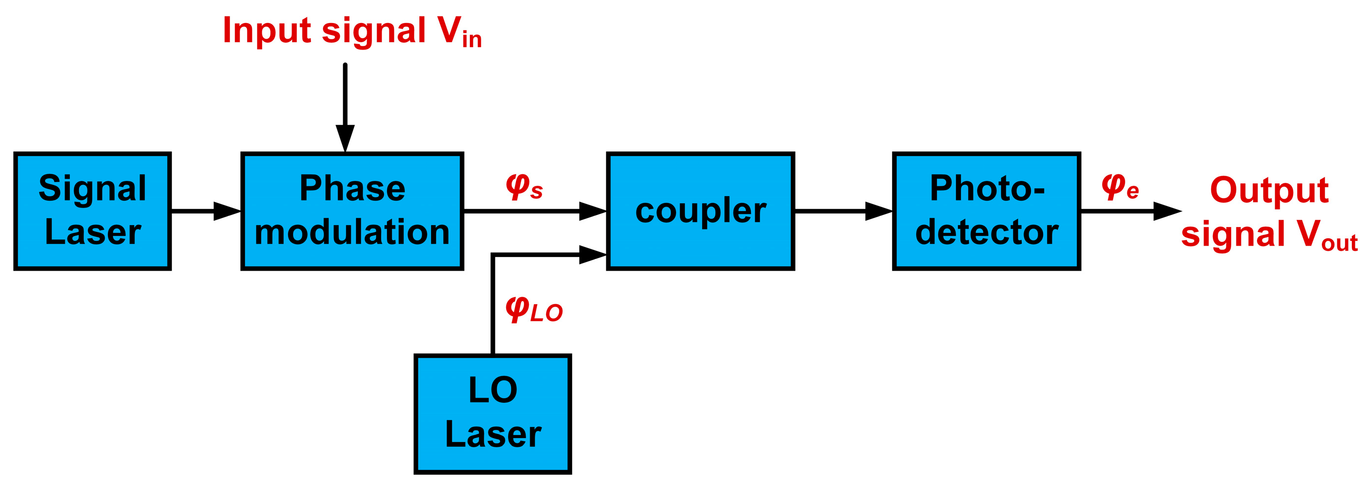
However, PM-CD MPLs still suffer from signal nonlinear distortions, primarily arising from the phase demodulation process at the receiver. This remains a critical challenge in the employment of such links. The schematic diagram of the PM-CD MPL without fiber link is presented in Figure 2.
In the transmitter, the input signal V i n is modulated onto signal light through a phase modulator (PM), causing the phase of signal light φ S to vary linearly along with the input signal. The modulated signal light is then transmitted to the receiver, where in coherent detection, the phase difference between the signal and LO light is converted into a photocurrent i P D , which is also influenced by the input power of both the signal and LO light, as well as the responsivity of the photodetector (PD). Then, this photocurrent is transformed into a voltage signal across the system load R L . The output signal V o u t can be denoted as
V out t = i PD R L = 2 r P S P LO sin φ e t R L ,
where P S and P L O are, respectively, the input power of signal light and LO light, r is responsivity of PD, φ S and φ L O are the phase of signal and LO light, respectively, and φ e = φ S φ L O , is the phase difference between the two, which, more importantly, implicitly contains the signal to be demodulated.
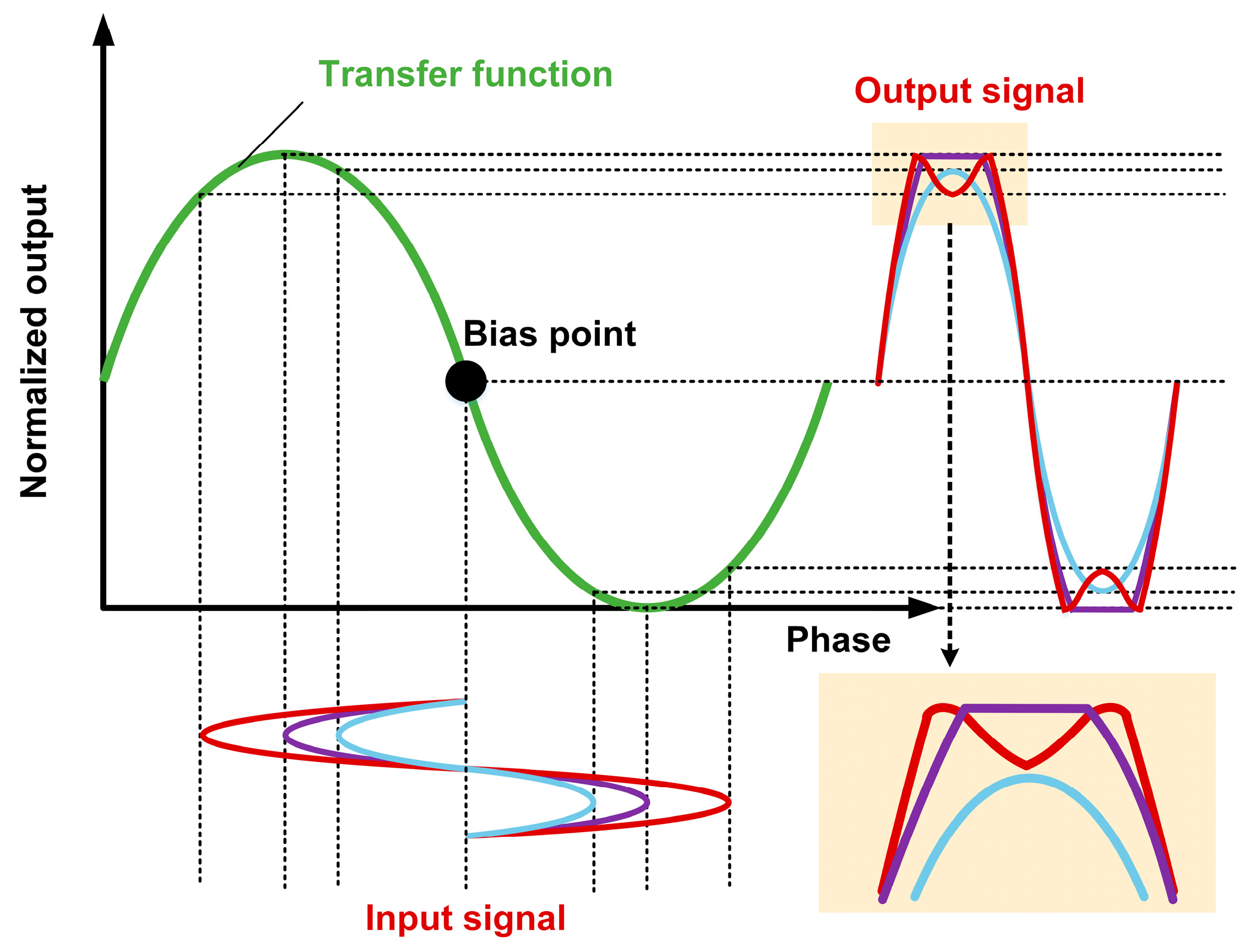
Obviously, the conversion process from the phase differences to the photocurrent or to the output signal, which exhibits a sinusoidal response to the optical phase, is the main source of the nonlinearity. Additionally, as illustrated in Figure 3, assuming the phase difference induced by the input signal varies in a sinusoidal form, the greater the phase difference, the more severe the distortion of the output signal. In the frequency domain, this type of distortion is primarily represented as intermodulation distortions (IMDs). Especially, IMD3, which resides in the baseband with respect to the signal of interest, can hardly be filtered out, is thus considered a primary factor in the degradation of transmission performance.
To date, many linearization techniques have been proposed. One of the representative technologies is coherent IQ phase demodulation based on digital signal processing [9,10]. The I and Q components at the output of the coherent receiver form a complex analytical signal, from which the DSP algorithm can be applied to extract the RF signal. However, with the complexity and digitizer-limited noise floor, the transmission performance is somewhat compromised. On the other hand, another approach to linearization involves manipulating phase modulation sidebands using optical filtering, polarization control, and spectral processing. This method effectively suppresses specific orders of nonlinear sidebands while transferring phase information into intensity, enabling direct detection [11,12,13,14,15,16]. In Reference [11], a spectral vector processor comprising a diffraction grating, lenses, a programmable liquid crystal, and mirrors is employed to regulate phase modulation sidebands. This process achieves two key functions: first, it converts originally out-of-phase odd-order sidebands into in-phase components, facilitating the transformation of phase information into intensity for subsequent direct detection; second, it adjusts the transmittance of individual sidebands to attenuate specific nonlinear spurious components, thereby improving system linearity. Similarly, Reference [13] realizes signal linearization by integrating polarization control with optical filtering for enhanced demodulation accuracy.
In addition, linearized coherent phase demodulation based on OPLL was demonstrated in many previous works [17,18,19,20,21,22,23,24,25,26]. Relying on OPLL, the demodulation is supposed to be preserved within the linear region of the sinusoidal response of photodetector. Consequently, highly precise phase tracking of the phase modulation at the transmitter end is implemented, permitting the suppression of overall distortions, i.e., distortions of all orders [17]. In this context, precise and tight phase locking with large loop bandwidth is desired for broadband phase tracking. With on-chip integration, extended receiver bandwidth up to ~1.45 GHz was demonstrated [17]. Except for component-level integration, extensive studies have been focused on phase modulator (PM) [23,24,25,26] in order to improve the modulation bandwidth. For instance, attenuation-counter-propagating PM was introduced, where the modulation signal propagates in the opposite direction with respect to the optical signal, effectively eliminating the propagation delay in the modulator [24,26].

2.3. Phase Noise in Long-Haul Transmission

In long-haul PM-CD MPLs systems, laser phase noise, ASE amplifier noise, and fiber link disturbances are the primary factors that increase system noise.
  • Laser phase noise refers to the fluctuations in the output light wave’s phase and frequency caused by various factors affecting the laser. In general, the theoretical limit of laser phase noise is determined by quantum noise. However, inevitable factors such as spontaneous emission noise, cavity impurities, cavity instability, temperature variations in the operating environment, vibrations, and pump noise all affect the stability of the laser’s output phase and frequency, leading to the degradation of laser phase noise.
  • OA is used in long-distance fiber optic links to compensate for link loss and ensure sufficient received optical power. However, the optical amplifier (e.g., Erbium-doped fiber amplifier, EDFA) introduces additional amplified spontaneous emission (ASE) noise, which induces intensity and phase noise on the optical carrier. ASE phase noise cannot be suppressed through balanced photodetection, thus becoming the dominant source of noise. ASE noise degrades system noise and ultimately affects signal demodulation in the link.
  • During the optical fiber link transmission, factors such as environmental temperature and vibrations cause random variations in the signal’s transmission delay. This is fundamentally due to the dependence of fiber length and refractive index on temperature and pressure. When the environmental temperature and pressure fluctuate due to external disturbances, the transmission delay of the fiber changes correspondingly. The variation in fiber transmission delay, after optical frequency amplification, is converted into phase changes. Since optical frequencies can reach hundreds of THz, even minor delay changes can cause significant phase jitter. Moreover, according to Reference [27], when external noise sources are spatially uncorrelated, the delay variation caused by fiber interference is proportional to fiber length. The longer the fiber, the more severely it is affected by external environmental disturbances.
All the forementioned noise sources contribute to phase noise φ n ( t ) in the system, causing random direct current (DC) drift i D C , which eventually affects the stability of the demodulation bias point. It can be denoted as
i BPD = 2 r P S P LO sin Δ ω t + φ e t + φ n t ,
i BPD = 2 r P S P LO sin φ e t cos φ n t + 2 r P S P LO cos φ e t sin φ n t 2 r P S P LO φ e t cos φ n t + Δ i DC .
This can be though partially mitigated by exploiting the specially designed counter-propagating loop configuration [28], a fiber stretcher has to be employed to compensate random phase fluctuations resulting from environmental perturbations. Due to the fact that the coherent nature of PM-CD MPLs makes them sensitive to phase fluctuation while the disturbance induced random phase fluctuations scale with the length of the fiber links, and a fiber stretcher could be only sufficient for fiber links within one kilometer [29]. From a practical point of view, the instability between the carrier and LO, the ASE noise introduced by EDFA, as well as the environment induced phase fluctuations for long-haul MPLs should be carefully addressed.

3. OPLL and Synchronous Transmission Based Linearized MPL

To address these challenges, we propose a composite OPLL architecture integrating AOFS-based stabilization and PM-based linearization, assisted by 2-core MCF, enabling 100 km field validation.

3.1. System Configuration Diagram

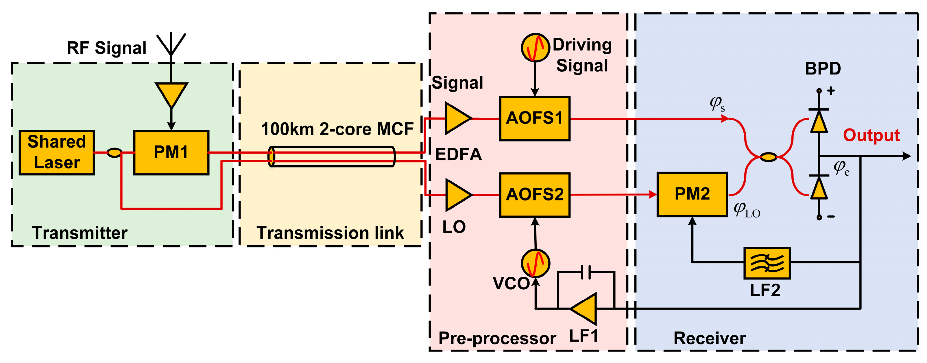
Figure 4 depicts the proposed PM-CD MPL system. In the transmitter unit, a fiber laser (NKT C15, NKT PHOTONICS, Birkerød, Denmark) operating at around ~1550 nm serves as the light source, with the output split into signal and LO paths by a 2 × 2 polarization-maintaining coupler (PMC). The RF signal received by the antenna drives the LiNbO3 phase modulator (MPX-LN-0.1, PHOTLINE, Besançon, France) in the signal path to modulate the phase of the signal light. The signal and LO lights are then transmitted through separate cores of a 100 km 2-core MCF (commercially available from YOFS, Havant, UK) to the receiver unit. In the pre-processor, both the signal and LO lights are first amplified by two commercial EDFAs (BG-EYDFA-C1, BEOGOLD TECHNOLOGY, Xiamen, China) to compensate for optical power loss, followed by a dual-frequency-shift homodyne OPLL composed of two AOFS (T-M040, Gooch and Housego, Ilminster, UK)to suppress optical amplification noise and link disturbances. The key point to emphasize is that both AOFS1 and AOFS2 can only shift the frequency upward in a unidirectional manner. Finally, in the receiver, a PM-based optical phase-locked loop is introduced to address the nonlinear issues in signal demodulation and output the demodulated signal.
The system utilizes balanced photodetection with a 50:50 optical coupler and a balanced photodetector (BPD), which consists of two commercial InGaAs photodiodes from Thorlabs Inc., effectively suppressing relative intensity noise and common-mode phase noise. A homodyne composite OPLL is implemented, consisting of an AOFS-based loop and a PM-based loop. The AOFS loop, incorporating an AOFS and a voltage-controlled oscillator (VCO) based driver, is responsible for stabilizing phase fluctuations between the signal and LO, ensuring proper signal demodulation. Meanwhile, the PM loop facilitates linearized signal demodulation. Both loops share a phase discrimination mechanism, which compares phase differences and generates corresponding error signals for precise feedback control.

3.2. Noise Compensation Using AOFS Loop and 2-Core MCF

In the system, a common-source laser generates both the signal and LO light, which are synchronously transmitted through a 2-core MCF. By implementing optical delay matching, the phase noise induced by inherent transmission delays as well as laser and EDFA phase noise is minimized. Moreover, since both beams experience the same transmission environment, environmental perturbations manifest as common-mode phase noise that can be effectively suppressed by balanced photodetection. Nevertheless, residual phase noise still persists and adversely affects signal demodulation, necessitating further compensation. Subsequently, the output of the BPD can be denoted as
i BPD = 2 r P S P LO sin Δ ω t + φ e t + φ n t ,
where ω is the frequency difference between the signal and LO light, φ e ( t ) under ideal condition is introduced by the RF signal to be demodulated, φ e t = φ S t = V i n ( t ) · π / V π , P M 1 , φ n ( t ) is the residual phase noise that disrupts this ideal condition.
AOFS loop is utilized to mitigate residual phase noise φ n ( t ) . According to automatic control theory, AOFS2 in cooperation with VCO can be regarded as an ideal integrator with infinite time constant under the control of the AOFS loop. A corresponding frequency shift f Δ τ is generated and integrated over 0 t f Δ f Δ τ d τ to accomplish the correction for the phase noise. As shown in Equations (5) and (6), the generated φ A O F S ( t ) and φ n ( t ) are equal in magnitude but opposite in phase, thus canceling out the phase difference except for φ e t induced by RF signal.
It is worth noting that although the signal and LO lights originate from the shared laser source, they experience independent propagation paths through long fiber links. Environmental disturbances, such as temperature variations and mechanical stress, introduce random fluctuations in the optical path delay and refractive index, which accumulate over distance. Subsequently, the signal and LO lights experience independent frequency drifts, making it practically impossible to maintain perfect frequency alignment at the receiver side. Therefore, the use of two AOFSs on the receiver side serves a specific purpose. Specifically, the AOFS1 in the signal light path generates a fixed frequency shift of 40 MHz under a constant signal drive, while the AOFS2 in the loop is driven by the feedback signal, with its frequency shift direction matching that of AOFS1. However, its frequency shift amount, centered around 40 MHz, varies in real time to compensate for the continuously changing phase noise and aligns the frequencies of the signal and LO light, ensuring the proper operation of the homodyne reception. In the results, the frequency difference between the signal and LO light ω is equal to zero. Consequently, φ e ( t ) is cleanly exposed.
φ AOFS t = 0 t f Δ f Δ τ d τ = φ n t ,
i BPD = 2 r P S P LO sin Δ ω t + φ e t + φ n t + φ AOFS t = 2 r P S P LO sin φ e t .
Owing to the theoretically infinite integration range, the long-term stability is permitted by the AOFS loop feedback control especially under the circumstance of long distance transmission, which would intuitively manifest in the elimination of DC drift. Then, linearized signal demodulation is accomplished via PM loop.

3.3. Linearized Demodulation Using PM Loop

The principle of linearized demodulation using the PM loop can be briefly summarized as restricting the demodulation process to the linear region of the sinusoidal phase-output response. In the Laplace domain, open loop transfer function of the PM loop is defined as G s ,
G s = K BPD F s K PM 2 e τ s ,
where s = j w , K B P D = 2 r ( P S P L O ) is optical gain, F ( s ) coming from loop filter LF1 is electrical gain. K P M 2 = π / V π , P M 2 is modulation factor of PM2. τ is loop delay of the PM loop.
When the PM loop is locked, the subsequent phase difference φ e , c l o s e s can be given by
φ e , close s = φ e . open s 1 + G s = φ S s 1 + G s ,
φ S s = V in s π V π , PM 1 = φ e , open s ,
where V π is half-wave voltage of local PM, V i n is input voltage of RF signal to be transmitted. As shown in Equations (6) and (7), on the one hand, under AOFS loop operation, the signal light and LO light maintain frequency and phase synchronization without RF input. When RF signals are applied, a phase difference proportional to the input RF characteristics is introduced between the two optical paths, so φ e , o p e n = φ S .
On the other hand, compared with the initial phase difference in the open-loop configuration, the PM loop closure induces significant difference compression by a factor of 1 / ( 1 + G ( s ) ) . When the loop gain G ( s ) exceeds critical thresholds, the phase difference φ e , c l o s e would asymptotically approach zero, i.e., a larger G s would lead to a smaller φ e , c l o s e s . In other words, it allows the input signal to be relatively large while still maintaining linear demodulation, thanks to the active locking mechanism. Combining with aforementioned analysis of sinusoidal phase-output response in Section 2.2, it is obvious that there is an approximately linear region in this response curve under small-signal conditions, thereby validating the linear approximation presented in Equation (8):
i BPD 2 r P S P LO φ e , close s = 2 r P S P LO φ S s 1 + G s .
This equation also indicates that the locking of PM loop brings 20 log 10 | ( 1 + G ( s ) ) | d B of power compression to demodulated signal. Finally, the photocurrent is ultimately converted into an output voltage through the output impedance, realizing the linearized demodulation of RF signal.
Along with the output signal, nonlinear spurious signals are also generated, with the most significant being the aforementioned IMD3. According to nonlinear theory, the output power of IMD3 increases with the input signal power. When the PM loop is closed, it will theoretically undergo even greater compression, with a ratio of 1 / 1 + G ( s ) 3 . That is to say, the IMD3 output power is reduced by approximately three times that of the compression amount of fundamental signal, i.e., 60 log 10 | ( 1 + G ( s ) ) | d B . This is strong proof that the PM loop can effectively suppress system nonlinearities as well.

4. Experimental Results and Discussion

A series of experiments has been conducted to validate the proposed long-haul synchronous transmission and linearized composite-loop OPLL structure, as shown in Figure 4. A stabilized continuous-wave narrow-linewidth fiber laser operating at ~1550 nm is located in the transmitter unit as the shared laser source. RF signals are generated by an arbitrary waveform generator before modulating the optical carrier at PM1. The V π of the PM1 and PM2 are approximately 4.5 V and 3.5 V, respectively. The AOFS1 in the signal path operates at precisely 40 MHz, while AOFS2 in the LO arm is controlled by the AOFS loop with a ~5 MHz modulation bandwidth. The input optical power has been optimized with respect to the BPD, which has a responsivity near 1 A/W.
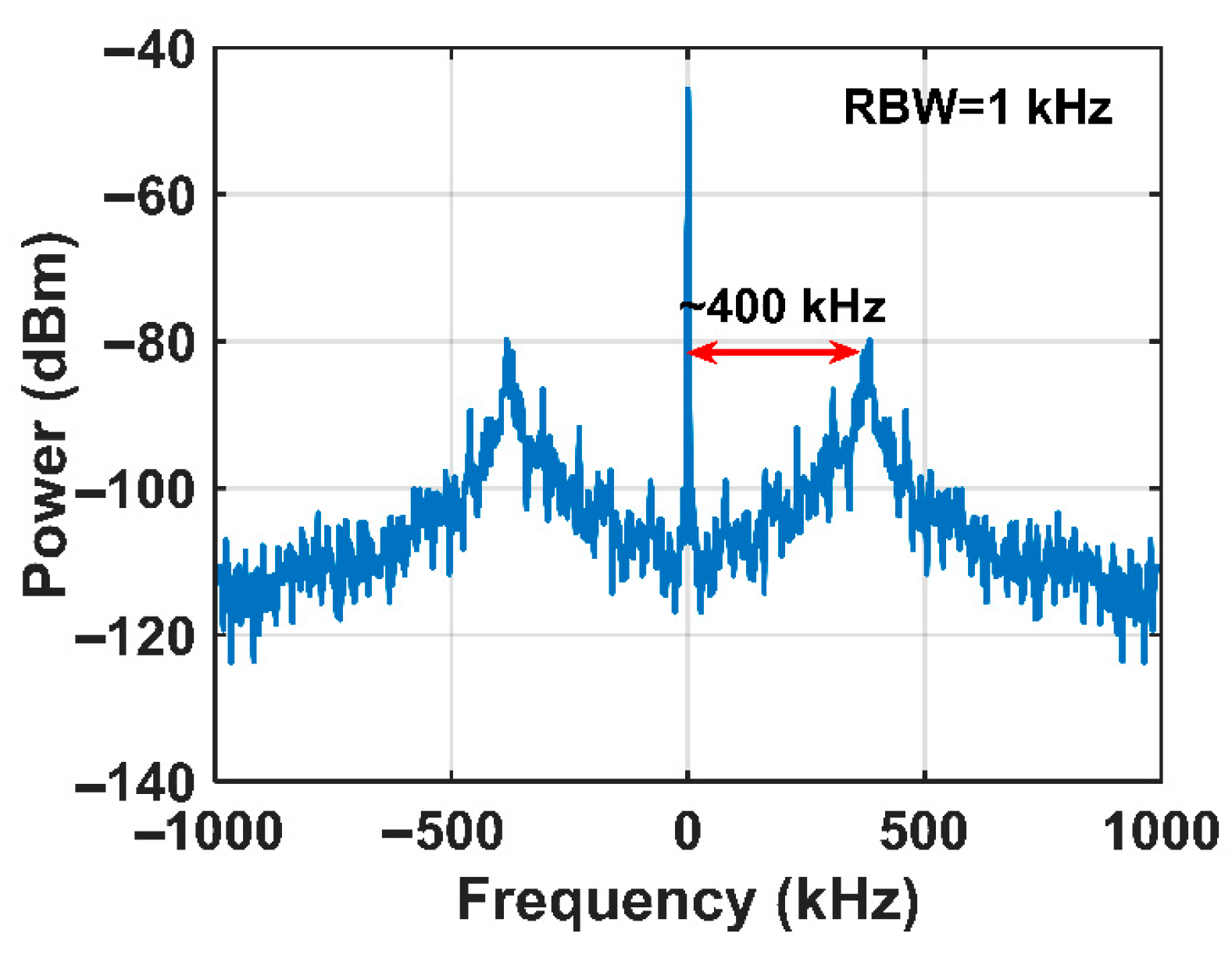
The loop bandwidth of the AOFS loop is primarily constrained by the acousto-optic propagation delay. The AOFS loop achieves a phase-locked bandwidth of approximately 400 kHz. As shown in Figure 5, within the bandwidth, the noise floor of the beat signal is effectively suppressed, with more than 20 dB suppression observed at low frequencies. In the proposed scheme with a 100 km-long fiber transmission link, the bandwidth is sufficient to preserve the system in phase-locked state, and phase noise, mainly located in the low frequency region induced by the surrounding environment fluctuations can be effectively suppressed.
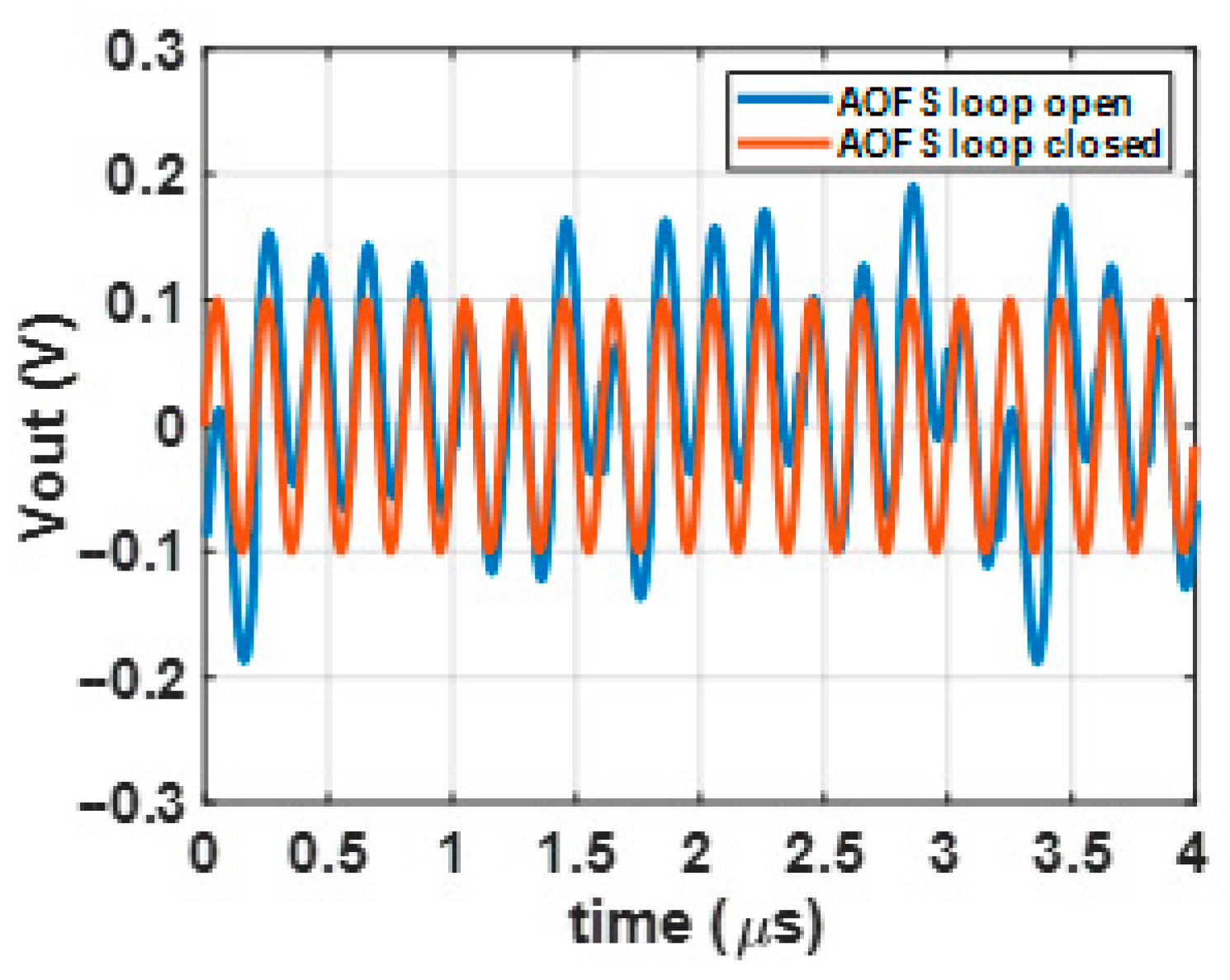
The effective suppression of phase noise not only reduces the system noise floor but also stabilizes the bias point of coherent optical phase demodulation. To validate the bias-point stabilization effect of the AOFS loop, a 5 MHz sinusoidal signal is applied to the signal light through PM1. Figure 6 shows the time-domain waveforms of the beat signal at the receiver output under open-loop and closed-loop conditions of the AOFS loop, respectively. When the AOFS loop is open, the output signal exhibits significant DC drift due to phase perturbations, which is well consistent with Equation (3). In contrast, when the AOFS loop is locked, the system generates a stable DC-free output signal, demonstrating the capability of the AOFS loop to suppress bias-point drift in coherent demodulation.
To evaluate the system’s transmission bandwidth and link gain, a signal generator is configured to produce a sinusoidal signal with a constant output power of 0 dBm across the frequency band from 0.5 MHz to 150 MHz, emulating RF signals received by an antenna. The signals are used to drive PM1 to induce optical phase modulation. The output power of the demodulated signals at receiver unit is measured using a real-time spectrum analyzer (RSA), as depicted in Figure 7.
As demonstrated in Figure 7, the MPL exhibits stable response characteristics within the 0.5~30 MHz frequency band, with an average link gain of approximately −6 dB and gain fluctuations confined to about ±1 dB. A distinct gain peak observed near 50 MHz indicates the operational bandwidth of the PM loop, which extends to approximately 50 MHz within the bandwidth, and a linearized demodulation of RF signals is achieved. The bandwidth of the PM loop is actually constrained by loop latency, which is mitigated through stringent control of optical component fiber pigtail lengths and optimized circuit layout design. These measures minimize propagation delays, enabling the PM loop to fully cover the shortwave frequency band requirements while maintaining signal integrity. Additionally, due to limitations in the laboratory conditions, chip-scale integration of the optoelectronic components could not be implemented. If such integration were feasible, the loop delay could be reduced to sub-nanosecond levels, thereby enabling loop bandwidths in the GHz range.
To evaluate the linearity of the proposed MPL, a two-tone test is conducted. A dual-tone signal with frequencies of 4.9 MHz and 5.1 MHz is applied to PM1 at the transmitter end for modulating the signal light. After transmission through a 100 km 2-core MCF link, the signal is demodulated at the receiver unit. The received optical power at the BPD is 10 dBm. The output signal spectra in both open-loop and closed-loop states of the PM loop are shown in Figure 8.
When the PM loop is in an open-loop state, it is equivalent to a conventional coherent demodulation system. Significant IMD3 can be observed at 4.7 MHz and 5.3 MHz, symmetrically located around the fundamental frequency signal with equal power, as shown in Figure 8a. In contrast, when the system is in a closed-loop locked state, the fundamental signal experiences approximately 27 dB of power compression compared to the open-loop state, while IMD3 undergoes a power compression about three times greater than that of the fundamental signal, that is about 81 dB as shown in Figure 8b. IMD3 is compressed almost under the noise floor indicating significant improvement of demodulation linearity. In addition, the experimental result aligns well with the theoretical analysis in Section 3.3, from which it can be inferred that the loop gain of the PM loop at 5 MHz is approximately 27 dB. This loop gain ensures the tight phase tracking of the LO light with respect to the signal light.
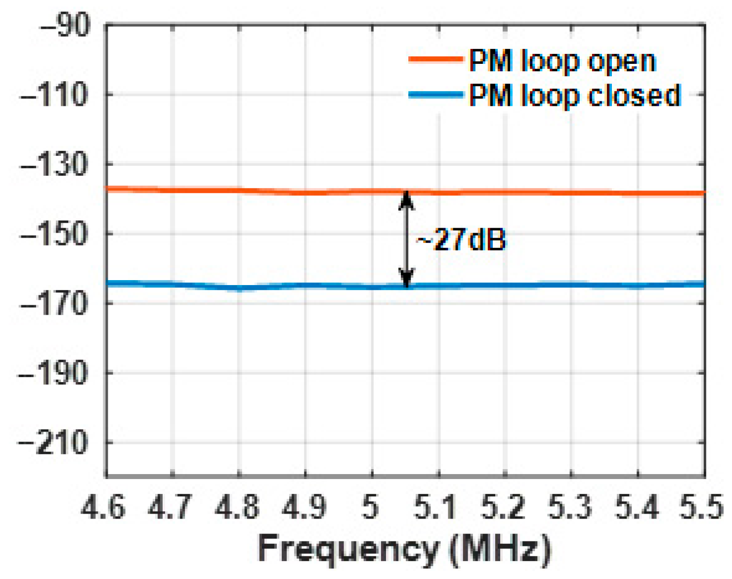
To further evaluate the system’s noise floor at the 5 MHz frequency, the noise floor could be measured without input signal. Since the system’s noise floor is significantly lower than the instrument’s noise floor, a power amplifier is used to amplify the signal before measurement. The results show that when the PM loop is closed, the noise floor exhibits a power compression similar to that of the fundamental signal compared to the open-loop state. It is worth noting that thanks to the equal proportions of compression for both fundamental signal and noise floor, the SNR of the proposed MPL stays the same without deficiency. As shown in Figure 9, after the PM loop is locked, the system’s noise floor at 5 MHz is approximately −167 dBm/Hz.

5. Conclusions

This study presents a robust framework for enhancing the reliability of secure communication systems in contested electromagnetic environments, with a focus on mitigating nonlinear distortions and phase noise in long-haul MPLs. The proposed system integrates a composite OPLL, accompanied by 2-core MCF architecture, achieving high-fidelity signal demodulation and environmental noise suppression. Specifically, by synergizing AOFS, PM loops, as well as 2-core MCF, the system achieves 81 dB suppression of the IMD3 and 27 dB suppression of the noise floor at 5 MHz, while maintaining ±1 dB gain stability over a 30 MHz bandwidth and 100 km long-haul transmission. Experimental validation highlights significant improvements in signal linearity and stabilization, underscoring the system’s applicability to military command and control infrastructures. These advancements demonstrate the feasibility of deploying spatially decoupled, interference-resistant communication networks in modern battlefield scenarios. Future efforts could explore bandwidth expansion, latency optimization, and scalable implementations to broaden both military and civilian applications of this technology.

Author Contributions

Conceptualization, Z.Z.; data curation, T.T.; formal analysis, W.X.; investigation, Y.L.; writing—original draft, Y.B.; writing—review and editing, D.Y. and H.S. All authors have read and agreed to the published version of the manuscript.

Funding

This research was funded by National Key Laboratory of Information Systems Engineering, 05202401.

Institutional Review Board Statement

Not applicable.

Informed Consent Statement

Not applicable.

Data Availability Statement

The data that support the plots in this paper and other findings of this study are available from the corresponding author on reasonable request.

Conflicts of Interest

Authors Yuanshuo Bai, Zhaochen Zhang and Yang Li were employed by the company China Electronics Technology Group Corporation. The remaining authors declare that the research was conducted in the absence of any commercial or financial relationships that could be construed as a potential conflict of interest.

References

  1. Spezio, A.E. Electronic warfare systems. IEEE Trans. Microw. Theory Tech. 2002, 50, 633–644. [Google Scholar] [CrossRef]
  2. Reddy, R.; Sinha, S. State-of-the-Art Review: Electronic Warfare Against Radar Systems. IEEE Access 2025, 13, 57530–57567. [Google Scholar] [CrossRef]
  3. Jaitner, M.; Mattsson, P.A. Russian Information Warfare of 2014. In Proceedings of the 2015 7th International Conference on Cyber Conflict: Architectures in Cyberspace, Tallinn, Estonia, 24–25 September 2015. [Google Scholar]
  4. Bowers, J.E.; Chipaloski, A.C.; Boodaghians, S.; Carlin, J.W. Long Distance Fiber-Optic Transmission of C-Band Microwave Signals to and from a Satellite Antenna. J. Light. Technol. 1988, 5, 1733–1741. [Google Scholar] [CrossRef]
  5. Ghelfi, P.; Laghezza, F.; Scotti, F.; Serafino, G.; Capria, A.; Pinna, S.; Onori, D.; Porzi, C.; Scaffardi, M.; Malacarne, A.; et al. A fully photonics-based coherent radar system. Nature 2014, 507, 341–345. [Google Scholar] [CrossRef] [PubMed]
  6. Capmany, J.; Novak, D. Microwave photonics combines two worlds. Nat. Photon 2007, 1, 319–330. [Google Scholar] [CrossRef]
  7. Swan, B.; Younger, B.; Smith, J.; Toll, M.; Smith, K. Communication, Proximity, and Trust in Distributed Command and Control. In Proceedings of the Human Factors and Ergonomics Society Annual Meeting, Lübeck, Germany, 17–19 April 2024; Volume 47, pp. 414–418. [Google Scholar]
  8. Woltjer, R.; Smith, K. Decision support through constraint propagation in collaborative distributed command and control. In Proceedings of the 2004 IEEE International Conference on Systems, Man and Cybernetics, Hague, The Netherlands, 10–13 October 2004; Volume 1, pp. 282–287. [Google Scholar]
  9. Clark, T.R.; O’Connor, S.R.; Dennis, M.L. A Phase-Modulation I/Q-Demodulation Microwave-to-Digital Photonic Link. IEEE Trans. Microw. Theory Tech. 2010, 58, 3039–3058. [Google Scholar] [CrossRef]
  10. Pei, Y.; Yao, J.; Xu, K.; Li, J. Advanced DSP technique for dynamic range improvement of a phase-modulation and coherent-detection microwave photonic link. In Proceedings of the 2013 IEEE International Topical Meeting on Microwave Photonics, Alexandria, VA, USA, 28–31 October 2013; pp. 72–75. [Google Scholar]
  11. Wu, R.; Jiang, T.; Yu, S.; Shang, J.; Gu, W. Multi-order nonlinear distortions analysis and suppression in phase modulation microwave photonics link. J. Light. Technol. 2019, 37, 5973–5981. [Google Scholar] [CrossRef]
  12. Li, P.; Yan, L.; Zhou, T.; Li, W.; Chen, Z.; Pan, W.; Luo, B. Improvement of linearity in phase-modulated analog photonic link. Opt. Lett. 2013, 38, 2391–2393. [Google Scholar] [CrossRef] [PubMed]
  13. Chen, Z.; Yan, L.; Pan, W.; Luo, B.; Zou, X.; Guo, Y.; Jiang, H.; Zhou, T. SFDR enhancement in analog photonic links by simultaneous compensation for dispersion and nonlinearity. Opt. Express 2013, 21, 20999–21009. [Google Scholar] [CrossRef]
  14. Li, J.; Zhang, Y.C.; Yu, S.; Gu, W. Optical sideband processing approach for highly linear phase-modulation/direct-detection microwave photonics link. IEEE Photon. J. 2014, 6, 1–10. [Google Scholar] [CrossRef]
  15. Zhu, D.; Chen, J.; Pan, S. Linearized phase-modulated analog photonic link with the dispersion-induced power fading effect suppressed based on optical carrier band processing. Opt. Express 2017, 25, 10397–10404. [Google Scholar] [CrossRef]
  16. Li, Y.; Wen, A.; Shan, D. An analog photonic down-conversion link with simultaneous IMD3 distortion suppression and dispersion-induced power fading compensation. J. Light. Technol. 2020, 38, 3908–3917. [Google Scholar]
  17. Ramaswamy, A.; Johansson, L.A.; Klamkin, J.; Bowers, J.E. Integrated Coherent Receivers for High-Linearity Microwave Photonic Links. J. Light. Technol. 2008, 26, 209–216. [Google Scholar] [CrossRef]
  18. Chou, H.F.; Johansson, L.; Zibar, D.; Bowers, J.E. All-Optical Coherent Receiver with Feedback and Sampling. In Proceedings of the 2006 International Topical Meeting on Microwave Photonics, Grenoble, France, 3–6 October 2006; pp. 1–4. [Google Scholar]
  19. Betts, G.E.; Krzewick, W.; Wu, S.; Yu, P.K.L. Experimental Demonstration of Linear Phase Detection. IEEE Photon. Technol. Lett. 2007, 19, 993–995. [Google Scholar] [CrossRef]
  20. Chou, H.F.; Ramaswamy, A.; Zibar, D.; Coldren, L.A. Highly Linear Coherent Receiver With Feedback. IEEE Photon. Technol. Lett. 2007, 19, 940–942. [Google Scholar] [CrossRef]
  21. Li, Y.; Herczfeld, P.R.; Rosen, A. Phase modulated fiber-optic link with high dynamic range. In Proceedings of the 2008 IEEE MTT-S International Microwave Symposium Digest, Atlanta, GA, USA, 15–20 June 2008; pp. 1457–1460. [Google Scholar]
  22. Li, Y.; Xu, L.; Jin, S.; Rodriguze, J.; Sun, T.; Herczfeld, P. Wideband OPLL photonic integrated circuit enabling ultrahigh dynamic range PM RF/photomic link. Optica 2019, 6, 1078–1083. [Google Scholar] [CrossRef]
  23. Wang, R.; Bhardwaj, A.S.; Li, Y. Highly linear InP phase modulator for high dynamic range RF/photonic links. In Proceedings of the 2010 IEEE MTT-S International Microwave Symposium, Anaheim, CA, USA, 23–28 May 2010; pp. 732–735. [Google Scholar]
  24. Li, Y.; Herezfeld, P.R. Novel attenuation-counter-propagating phase modulator for highly linear fiber-optic links. J. Light. Technol. 2006, 24, 3709–3718. [Google Scholar] [CrossRef]
  25. Xu, L.; Jin, S.; Li, Y. Nonlinear Phase Modulation Inside an MQW Optical Modulator. J. Light. Technol. 2016, 34, 3300–3305. [Google Scholar] [CrossRef]
  26. Li, Y.; Bhardwaj, A.; Wang, R.; Herczfeld, P. A Monolithically Integrated ACP-OPLL Receiver for RF/Photonic Links. IEEE Photon. Technol. Lett. 2011, 23, 1475–1477. [Google Scholar] [CrossRef]
  27. Kéfélian, F.; Jiang, H.; Lemonde, P.; Santarelli, G. Ultralow-frequency-noise stabilization of a laser by locking to an optical fiber-delay line. Opt. Lett. 2009, 34, 914–916. [Google Scholar] [CrossRef]
  28. Li, R.; Han, X.; Chen, X.; Chen, X.; Yao, J. A Phase-Modulated Microwave Photonic Link With an Extended Transmission Distance. IEEE Photon. Technol. Lett. 2015, 27, 2563–2566. [Google Scholar] [CrossRef]
  29. Shilei, J.; Xu, L.; Li, Y. Modified Sagnac Loop Coherent Phase Modulated RF Photonic Link With an ACP-OPLL. IEEE Photon. Technol. Lett. 2017, 29, 1139–1142. [Google Scholar]
Figure 1. Schematic diagram of MPL. E/O: electrical-to-optical; O/E: optical-to-electrical; O/O: optical-to-optical.
Photonics 12 00893 g001
Figure 2. Schematic diagram of PM-CD MPL without fiber link between transmitter and receiver. LO: local oscillation.
Photonics 12 00893 g002
Figure 3. Phase-to-current sinusoidal transfer function of coherent phase modulation.
Photonics 12 00893 g003
Figure 4. Diagram of Schemes of proposed MPL. PM: phase modulator, MCF: multi-core fiber, EDFA: Erbium-doped fiber amplifier, AOFS: acoustic optical frequency shifter, BPD: balanced photodetector, VCO: Voltage Controlled Oscillator, LF: Loop Filter.
Photonics 12 00893 g004
Figure 5. Beat spectrum of system when the AOFS loop is closed.
Photonics 12 00893 g005
Figure 6. Output signal when the AOFS loop is open or closed.
Photonics 12 00893 g006
Figure 7. Measurement of system bandwidth.
Photonics 12 00893 g007
Figure 8. Two-tone test results at 5 MHz when PM loop is open or closed. (a) PM loop is open, (b) PM loop is closed.
Photonics 12 00893 g008
Figure 9. Noise floor at 5 MHz with PM loop open or closed.
Photonics 12 00893 g009
Disclaimer/Publisher’s Note: The statements, opinions and data contained in all publications are solely those of the individual author(s) and contributor(s) and not of MDPI and/or the editor(s). MDPI and/or the editor(s) disclaim responsibility for any injury to people or property resulting from any ideas, methods, instructions or products referred to in the content.