Article

High-Precision Angle Sensor Based on Angle Amplification via Double-Layer Regular Prism Structure

College of Electrical and Information Engineering, North Minzu University, Yinchuan 750021, China
*
Author to whom correspondence should be addressed.
Photonics 2025, 12(9), 890; https://doi.org/10.3390/photonics12090890
Submission received: 7 August 2025 / Revised: 22 August 2025 / Accepted: 3 September 2025 / Published: 4 September 2025
(This article belongs to the Special Issue Optical Sensors and Devices)

Abstract

In this paper, a high-precision sensor for angle measurement with angle amplification based on the double-layer regular prisms structure was designed. The angle amplification was achieved by multiple reflections of the measurement laser between the inner and outer double-layer regular prism structure. The trajectory of the measurement laser within the double-layer regular prism structure was investigated, and a corresponding mathematical model was developed. A position-sensitive detector (PSD) measures displacement variations in the measurement laser and ultimately enables angle measurement by applying the displacement-to-angle conversion relationship derived from analysis of the reflection trajectory model. The sensor prototype achieved a measurement precision of ±0.5″. Additionally, the feasibility of the alternative measurement method using multiple measurement units was experimentally verified, while its measurement accuracy remained comparable to that of a single unit. The 360° angle measurement through proper arrangement of multiple PSDs can be achieved as well, and its feasibility has been discussed.

1. Introduction

Precision angle measurement constitutes a critical enabler of modern technological advancement, with extensive applications spanning aerospace, mechanical manufacturing, defense industries, and scientific research [1]. Against the backdrop of continual scientific and technological progress, metrological requirements for measurement equipment accuracy escalate relentlessly [2]. This demand extends to advanced material characterization techniques in scientific research, where precise angular positioning is often crucial for analyzing crystal structures and properties [3]. Conventional angle measurement methodologies fail to satisfy the demands of contemporary industrial development. Illustrative cases include spacecraft attitude control systems necessitating ultra-high-precision angular sensing to ensure orbital positioning accuracy, and high-performance computer numerical control (CNC) machine tools requiring precise angular metrology to enhance manufacturing precision [4]. Unlike displacement sensing, angular information typically resists direct acquisition by sensors, compelling many high-precision angular measurement techniques to rely on sophisticated displacement quantification methods [5,6,7,8,9]. Consequently, developing novel angle measurement technologies that deliver enhanced accuracy, stability, and operational efficiency carries substantial practical significance.
Angle measurement technologies are conventionally categorized into mechanical, electrical, and optical methodologies [4]. Mechanical and the majority of electrical methods are contact-based approaches, which can achieve relatively high accuracy, and are technologically simple and mature. However, their applications are often limited, resulting in scarce research in recent years [10,11,12]. Among these, optical approaches have garnered significant research attention in recent years due to their exceptional measurement accuracy, robust interference immunity, and dynamic measurement capabilities. The versatility of optical methods also supports their use in diverse spectroscopic applications, including mineral characterization, where precise angle control underpins the acquisition of meaningful data [4]. Notable innovations in this domain include a 360° non-contact angle sensor leveraging eddy-current effects, which utilizes a grooved aluminum tube and piecewise linear algorithms to achieve 0.08° resolution with 0.25% non-linearity [13,14]; a two-dimensional angle sensor employing a diffractive optical element (DOE) dot array that mitigates random errors and periodic nonlinearity through multi-peak detection, attaining stability below 0.0003″ [15]; and an improved three-center variable-eccentricity model addressing accuracy degradation in high-precision optical angular sensors caused by installation misalignment. This model uniquely identifies shifted sinusoidal phase-difference variations between opposing read-head signals during rotation, with experimental validation confirming <0.1 μm deviation between mechanical measurements and model predictions [16]. Further advancements encompass an integrated autocollimator-optical polygon framework for systematic error analysis and compensation [15], a phase-shifting Twyman–Green interferometer demonstrating 0.02″ standard uncertainty in polygon metrology [17], and a vertical angle calibration system combining precision rotation stages with miniature diffractive autocollimators to achieve 0.01″ resolution at 0.19″ expanded uncertainty [18]. Applied developments feature fiber Bragg grating (FBG) sensors for orthotic strain/angle monitoring (6.15 με, 0.30° precision during gait) [19], and a medical fiber-optic tilt sensor with 50% volumetric reduction via plastic packaging (±20° range) [20].
This paper presents an angular sensor architecture leveraging laser multiple reflections for angle amplification, enabling the creation of a high-precision angular measurement system. Within this configuration, the measurement laser undergoes five reflections between non-parallel mirrors to amplify angular displacement, ultimately impinging on the PSD active area. The target angle is derived from recorded displacement relationships, with the displacement-to-angle conversion methodology explicitly formulated and analyzed. Experimental validation confirms system feasibility, demonstrating angular measurement uncertainty within ±5″. Furthermore, range expansion is achieved through multi-unit deployment.

2. Principle of Angle Measurement

The schematic diagram of the angle amplification of laser multiple reflections at an angle in the reflection cavity composed of the inner and outer regular prism reflection structure is shown in Figure 1.
First, using the yz-plane as the principal section, when the incidence angle is fixed at 45° and the inner and outer reflectors are parallel, the length of the reflector surfaces can be designed to ensure that the measurement laser beam undergoes exactly five reflections before accurately reaching the photosensitive plane of the PSD, as shown in Figure 1a.
When the xy-plane is used as the principal section, the measurement laser beam always enters the system at normal incidence. When the inner and outer reflectors are parallel, the reflected beam emerges at 0°, landing at one end of the PSD’s effective detection area, as shown in Figure 1b. As the inner reflector rotates by an angle of θ, the reflected beam no longer exits at the same angle. Instead, after undergoing five reflections, it reaches the PSD target plane. The angle Θ between the emergent direction of the probe laser and the vertical exit direction depends on the rotation angle θ of the inner reflector and the number of reflections k that the probe laser has in the inner reflector, expressed as
Θ = 2 k θ
where the total number of reflections is fixed at five, with three of these reflections occurring on the inner reflector (i.e., k is fixed at 3). This structure thus achieves a sixfold angular amplification of the original minute rotation angle θ. The rotation angle θ can then be precisely measured by detecting the position where the probe laser strikes the PSD target plane.
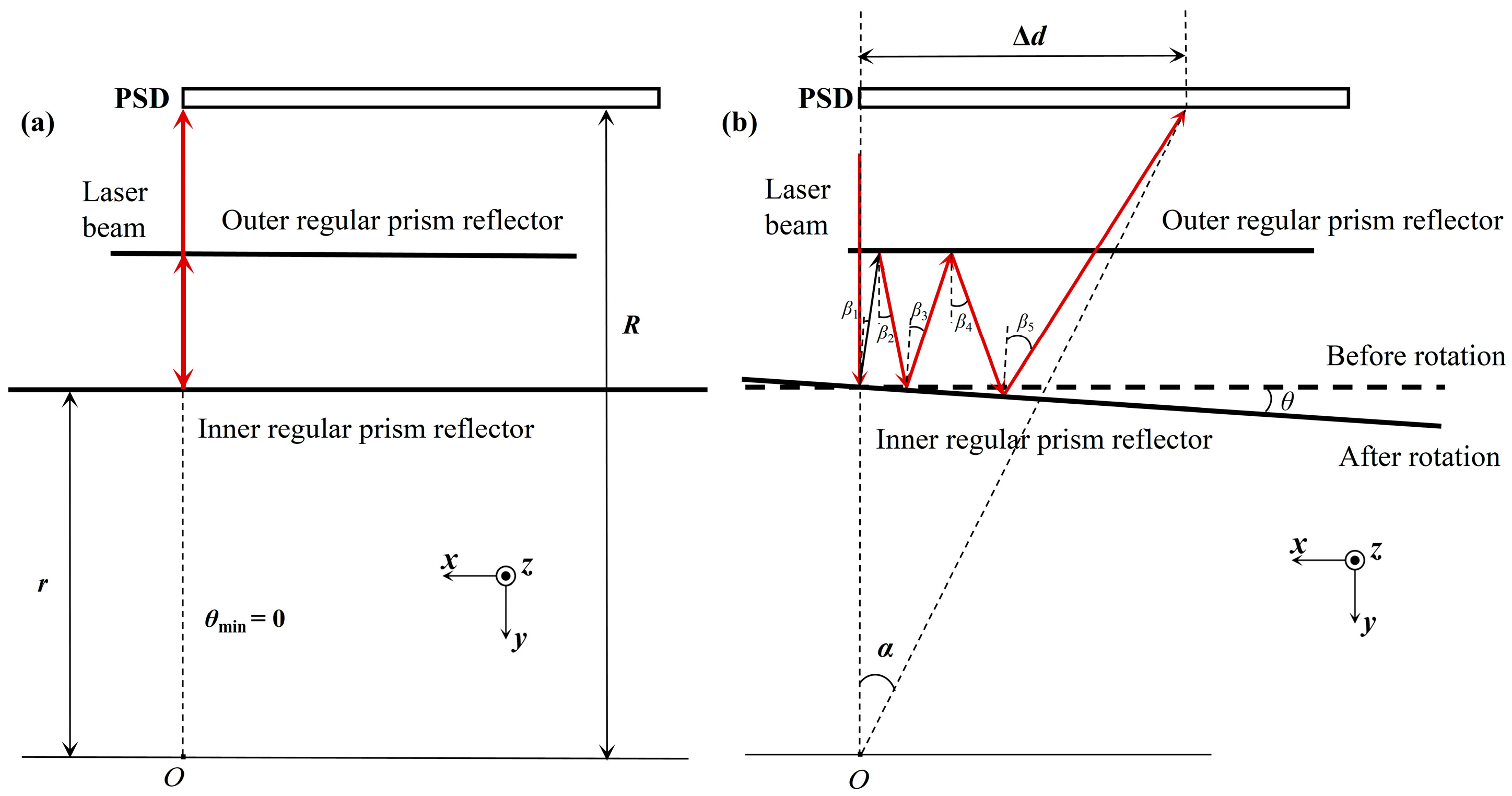
The schematic diagram illustrating the principle of converting displacement to angle is shown in Figure 2. The distance between the rotation axis and the inner reflector is set as r, and the distance to the PSD detection plane is R. When the inner and outer reflectors are parallel, the measurement laser spot falls at one end (reference point) of the effective area on the PSD, as shown in Figure 2a. When there is an angle θ between the inner and outer reflectors, the distance between the laser spot position on the PSD and the parallel-case endpoint position is Δd. For small deflection angles θ, the relationship α ≈ 6θ holds, as shown in Figure 2b. Therefore, the desired angle θ can be calculated using the following formula:
θ α 6 = arctan Δ d R 6
As the angle to be measured increases, the error introduced by the approximation gradually becomes non-negligible. Therefore, the size of each inner reflector in the sensor system can be reduced. As the angle increases, the inner reflector that is in use is dynamically switched to ensure the systematic error remains within an acceptable level.

3. Experimental and Results

3.1. Hardware Implementation of the Sensor System

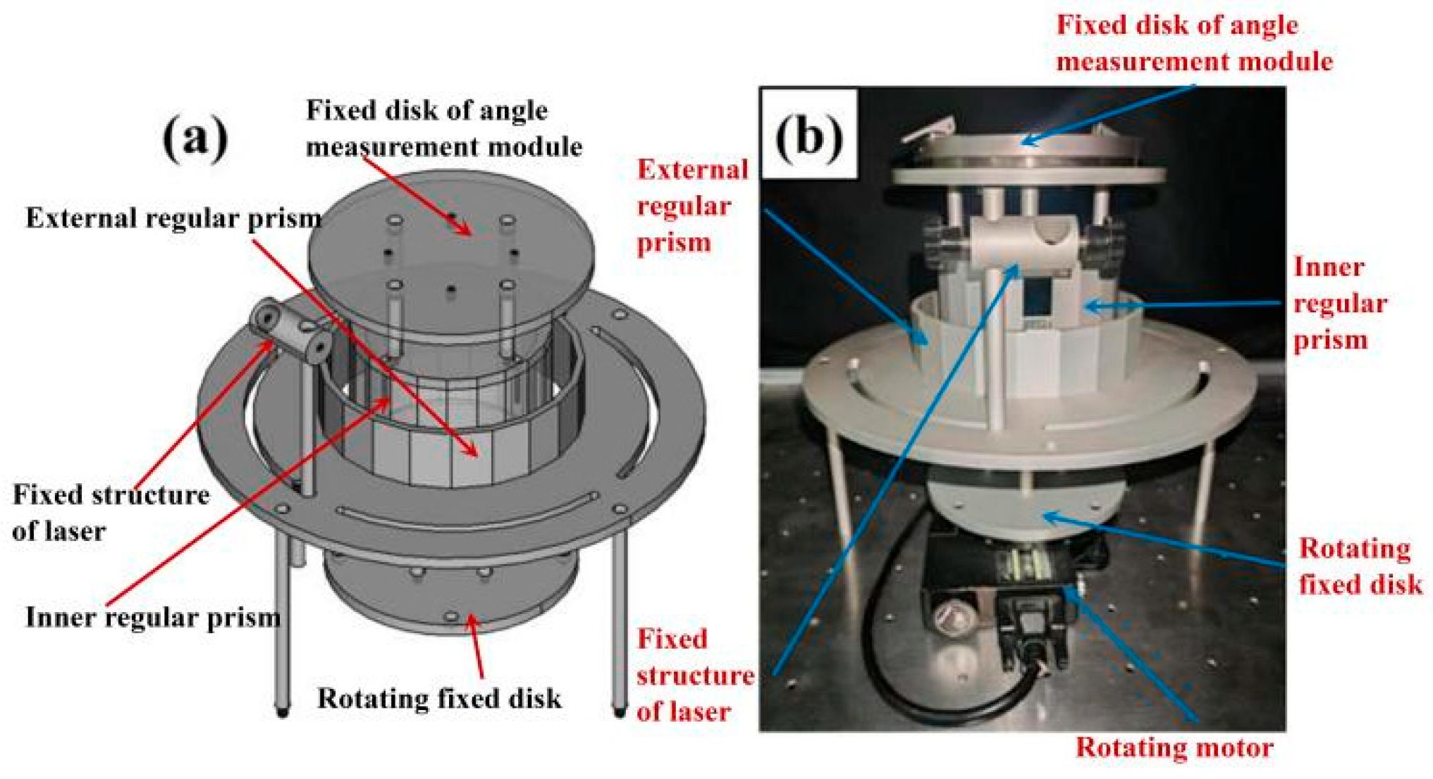
The mechanical configuration of the sensor is depicted in Figure 3. When the inner and outer mirrors are parallel, the distance between them is 1.5 cm. To enable synchronous rotation of the inner regular prism with the angle-adjustment turntable, a dedicated chassis integrates both components. For rigid coupling between the XR20-W unit and the inner regular prism, a custom-fabricated cover matching the prism dimensions is implemented. This cover interfaces with the XR20-W mounting base via four positioning rods. Concurrently, the outer regular prism is secured by four support rods, featuring a machined groove to accommodate the laser generator.
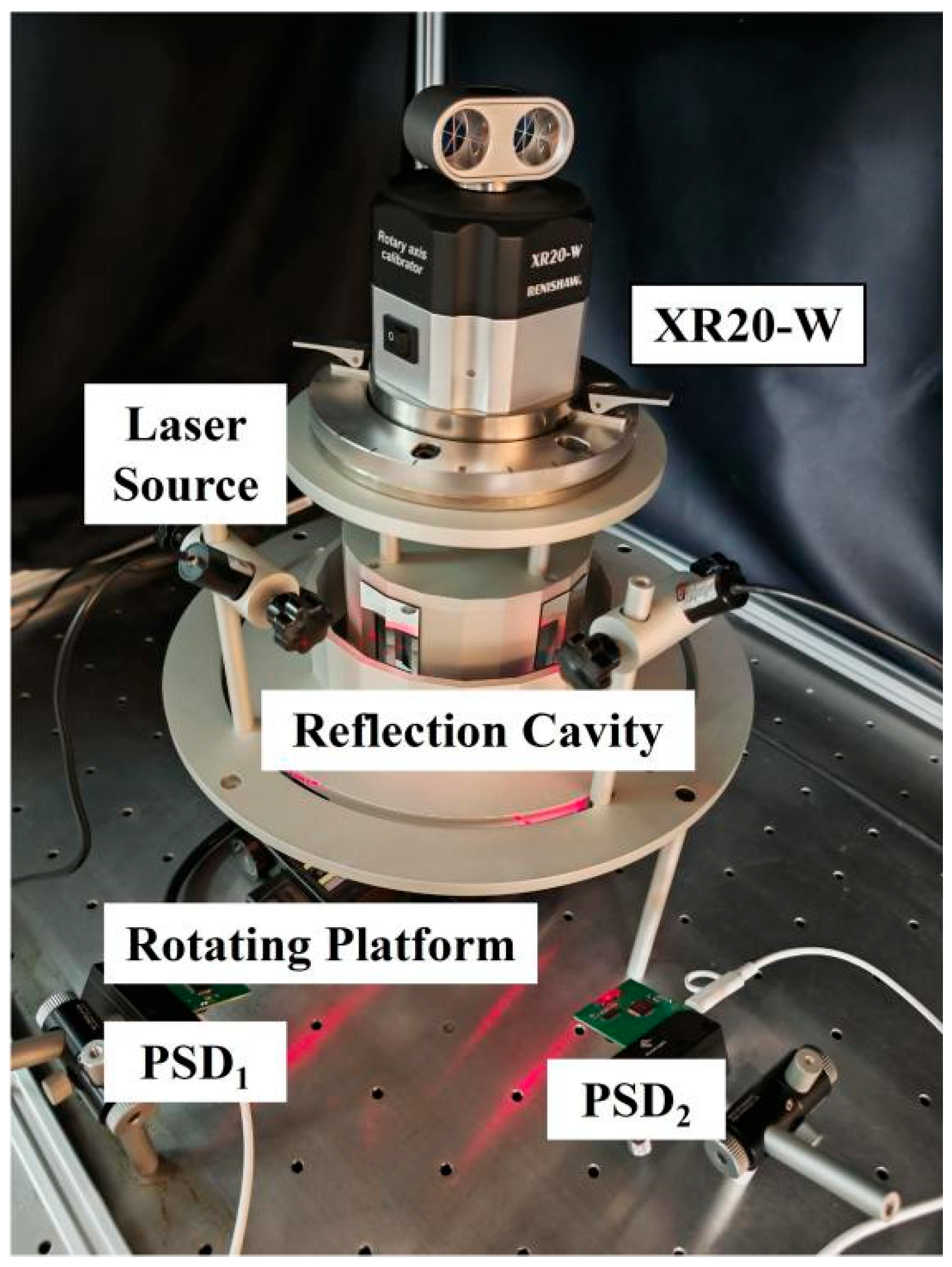
The physical prototype of the complete sensor system is presented in Figure 4. The system primarily adopts the dual-reflector structure detailed in the Section 2, amplifying the target angle through multiple reflections. The laser (model FU655AD5-GD1670, produced by Dongguan Yiquan Electronic Technology Co., Ltd., Dongguan, China.), with a wavelength of 650 nm, a spot size of ~2 mm, and a rated power of 5 mW) is rigidly coupled to the stationary housing; meanwhile, the inner prism is affixed to the rotational platform. The PSD is externally mounted to the sensor assembly. Its photosensitive surface measures 0.1 × 1.2 cm2, but only an area of approximately 0.1 × 0.3 cm2 is utilized due to significant measurement inaccuracies observed near both edges. After undergoing five reflections within the optical path, the measurement laser beam impinges on the effective photosensitive area of the PSD. Positional data is subsequently acquired and converted to determine the target angle.
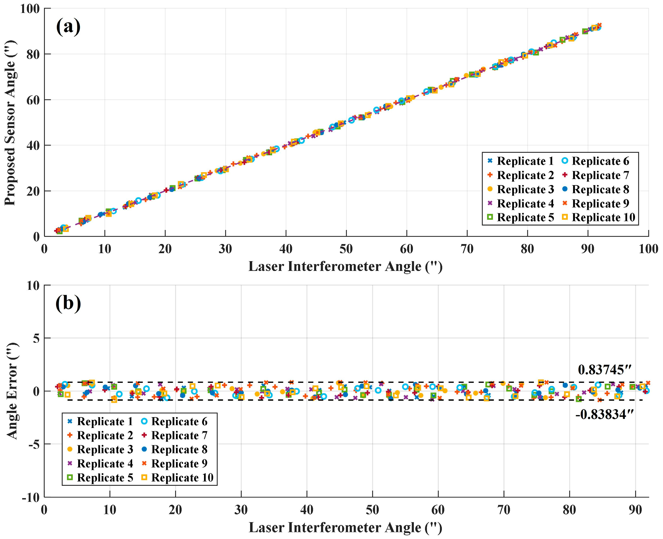
To validate the measurement principle and accuracy of the sensor prototype, comparative experiments were conducted against the Renishaw XR20-W angular measurement module (±1″ accuracy). Experimental datasets from multiple trials were processed to quantify measurement deviations. Ten experimental replicates were performed, with measured angles and corresponding errors depicted in Figure 5a and Figure 5b, respectively. Comparative analysis demonstrates close agreement between the developed sensor and XR20-W (Renishaw plc, London, UK) laser interferometer measurements, exhibiting mutual discrepancies within ±0.85″. Considering the intrinsic ±1″ uncertainty of the XR20-W reference system, both instruments demonstrate comparable measurement precision.
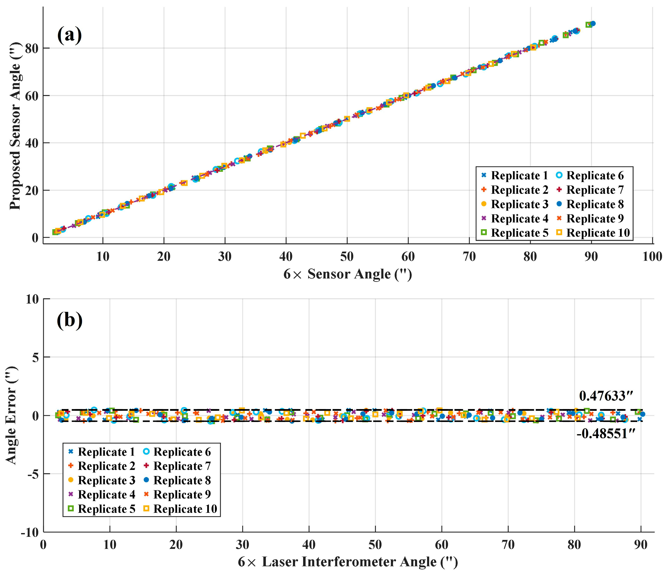
To more accurately evaluate the measurement precision of the developed sensor, the distance R between the rotation axis center and the PSD was increased 6× to enhance theoretical accuracy, serving as a reference experiment for the baseline sensor configuration. The data from ten replicates and the scatter plot of their errors are shown in Figure 6a and Figure 6b, respectively. This extended detector distance theoretically enables measurement precision of ±0.17″. However, this improvement entails a proportional increase in both the physical dimensions of the sensor and the alignment complexity.

3.2. Expanding the Measurement Range with Coordinated Sensor Units

To extend the sensor’s measurement range, a multi-units alternating measurement strategy was implemented for continuous angular monitoring. This approach achieves uninterrupted measurement through coordinated spatial distribution of discrete sensing units. When one unit approaches its blind zone, adjacent units enter effective measurement ranges, ensuring ≥2 units remain operational at transition boundaries to enable seamless probe alternation. With the laser interferometer as the calibration reference, the measurement data and corresponding error distributions are shown in Figure 7, denoted by blue and red scatter points, respectively.
Figure 7 demonstrates close agreement between measurement datasets from both sensing units within the overlap region. During transition phases of probe alternation, the system maintains measurement uncertainty within ±1″ across the overlapping measurement zones.

4. Discussion

The angular amplification measurement principle of the double-layer regular prism structure designed in this paper enables large-range 360° measurement. By fully utilizing the angular bisection principle of the regular prism, the 360° range is divided into smaller angular segments. Taking a 72-facet regular prism as an example, each prism facet corresponds to 5°. After the prism rotates by 5°, the relative position between the measurement unit and the prism resets to its initial state. Therefore, deploying multiple measurement units enables continuous, alternate measurement of 5° segments, achieving seamless 360° angular measurement. For instance, assuming each measurement unit has a measurement range of 0.5°: After the first measurement unit completes its 0.5° measurement, the second measurement unit enters its initial measurement position. Upon completion by the second unit, the third measurement unit assumes its initial position, and so forth. After the last measurement unit finishes its measurement range, the reciprocal positions of the prism and all measurement units reset to the initial state, facilitating the measurement of the next 5° segment. Existing experimental data confirm that the alternate detection by the measurement units has a minimal impact on measurement accuracy. Consequently, based on specific application scenarios or operating conditions, this configuration can be utilized to construct high-precision, large-range 360° angular measurement equipment.

5. Conclusions

This research establishes the measurement principle for an angle sensor utilizing an inner–outer double-layer regular prism structure, where multiple reflections of the measurement laser achieve significant angular amplification. Displacement of the resultant laser spot is quantified using a position-sensitive detector (PSD). To extend the measurement range, an alternate measurement strategy with multiple measurement units was implemented. It is noteworthy that the sequential replacement design of our system fundamentally avoids the risk of the measurement beam exceeding the boundaries of the PSD’s active area, which is a significant advantage over conventional fixed-sensor configurations. Experimental validation via a prototype sensor confirmed the correctness of the prism-based angle amplification principle and the feasibility of the multi-unit alternation approach, achieving a measurement accuracy of ±0.5″ while successfully expanding the range through dual-unit operation. By leveraging the angular bisection property of the regular prism for 360° segmentation and strategically positioning multiple measurement units to enable sequential range coverage, continuous full-circle measurement becomes theoretically achievable.
The proposed method features a structurally simple design, with potential for further accuracy enhancement through increased laser reflections, demonstrating significant promise for high-precision angular metrology applications. Based on the achieved measurement precision of ±0.5″ and the compact, multi-unit alternate measurement structure, this sensor demonstrates significant potential for application in fields requiring ultra-high-precision angular positioning. Its capabilities are particularly suited for satellite attitude control systems, high-end CNC machine tool calibration, precision optical platform leveling, and other ultra-high-precision applications in aerospace, advanced manufacturing, and scientific instrumentation. The robust design, which enables seamless 360° measurement, further supports its use in continuous rotation platforms and closed-loop control systems where both wide range and exceptional accuracy are critical.

Author Contributions

Conceptualization, B.Z. and Y.L.; Methodology, B.Z. and X.C.; Validation, L.S. and C.Z.; Formal analysis, B.Z. and L.S.; Investigation, X.C., Z.Y. and X.K.; Resources, C.Z. and Y.L.; Data curation, Z.Y. and X.K.; Writing—original draft, B.Z. and X.C.; Writing—review & editing, C.Z. and Y.L.; Visualization, L.S. and X.K.; Supervision, Y.L.; Project administration, Y.L.; Funding acquisition, Y.L. All authors have read and agreed to the published version of the manuscript.

Funding

B.Z. and X.C. are supported by National Natural Science Foundation of China (No. 52465062); Natural Science Foundation of Ningxia (No. 2022AAC02045 and No. 2024AAC03188); Innovation Project for the 2022 Graduate Students of North Minzu University (No. YCX24110).

Data Availability Statement

Data are contained within the article.

Conflicts of Interest

The authors declare no conflict of interest.

References

  1. Chen, G. Improving the angle measurement accuracy of circular grating. Rev. Sci. Instrum. 2020, 91, 065108. [Google Scholar] [CrossRef] [PubMed]
  2. Wang, C.; Meng, X.; Krolczyk, G.; Wei, H. A cluster-based method for quantitative characterization and uncertainty evaluation of areal step height in structured surface metrology. IEEE Trans. Instrum. Meas. 2022, 71, 3205662. [Google Scholar] [CrossRef]
  3. Kang, W.R.; Zheng, Z.Y.; Huang, H.C. Advancements in Digital Holography for Crystalline Material Characterization: A Review. Cryst. Res. Technol. 2025, 60, 2400264. [Google Scholar] [CrossRef]
  4. Wang, S.; Ma, R.; Cao, F.; Luo, L.; Li, X. A review: High-precision angle measurement technologies. Sensors 2024, 24, 1755. [Google Scholar] [CrossRef] [PubMed]
  5. Podlaskin, B.G.; Guk, E.G.; Obolenskov, A.G.; Sukharev, A.A. Improvement of the accuracy of a position-sensitive detector with a wide field of view. Tech. Phys. Lett. 2020, 46, 988–990. [Google Scholar] [CrossRef]
  6. Vittone, E.; Provatas, G.; Nizić, K.I.; Jaksic, M. IBIC analysis of a linear position sensitive detector: Model and experiment. Eur. Phys. J. Plus 2025, 140, 369. [Google Scholar] [CrossRef]
  7. Elrawashdeh, Z.; Revel, P.; Prelle, C.; Lamarque, F. High precision machining of a displacement sensor for helicoidal motions. Int. J. Precis. Eng. Manuf. 2022, 24, 409–422. [Google Scholar] [CrossRef]
  8. Guillen-Ruiz, L.E.; Anzueto-Sánchez, G.; Martínez-Rios, A.; Jiménez-Mares, M.C.; Martin-Vela, J.A. High-sensitivity displacement sensor using few-mode optical fibers and the optical vernier effect. Appl. Sci. 2024, 14, 9300. [Google Scholar] [CrossRef]
  9. Huang, H.C.; Liu, Z.; Ruggiero, M.T.; Zheng, Z.; Qiu, K.; Li, S.; Zhang, Z.; Zhang, Z. Terahertz Geoscience: THz Time-Domain Spectroscopy for Mineral Materials. Cryst. Growth Des. 2025, 25, 3578–3594. [Google Scholar] [CrossRef]
  10. Zhang, B.; Jiang, Z.; Yin, Z.; Cao, X.; Zhou, C.; Kang, X. Angle Sensor Based on Multiple Optical Arm Amplification. Int. J. Opt. 2025, 2025, 9979341. [Google Scholar] [CrossRef]
  11. Murai, T.; Uchiyama, S.; Nakamura, K.; Ido, Y.; Hata, Y.; Kato, H. Functional range of motion in the metacarpophalangeal joints of the hand measured by single axis electric goniometers. J. Orthop. Sci. 2018, 23, 504–510. [Google Scholar] [CrossRef] [PubMed]
  12. Nwaobi, O.M. Electric Goniometer for Positioning Children with Cerebral Palsy: Suggestion from the Field. Phys. Ther. 1986, 66, 1540–1541. [Google Scholar] [CrossRef] [PubMed]
  13. Kumar, A.S.A.; George, B. A non-contact angle sensor based on eddy current technique. IEEE Trans. Instrum. Meas. 2019, 69, 1275–1283. [Google Scholar] [CrossRef]
  14. Kumar, A.S.A.; George, B.; Mukhopadhyay, S.C. Technologies and applications of angle sensors: A review. IEEE Sens. J. 2021, 21, 7195–7206. [Google Scholar] [CrossRef]
  15. Kim, J.A.; Lee, J.Y.; Kang, C.S.; Woo, J.H. High-precision two-dimensional angle sensor using a dot array of a diffractive optical element. Meas. Sci. Technol. 2021, 32, 105204. [Google Scholar] [CrossRef]
  16. Larichev, R.; Filatov, Y. A model of angle measurement using an autocollimator and optical polygon. Photonics 2023, 10, 1359. [Google Scholar] [CrossRef]
  17. Eves, B.J.; Leroux, I.D.; Cen, A.J. Phase shifting angle interferometer. Metrologia 2023, 60, 055006. [Google Scholar] [CrossRef]
  18. Kim, J.A.; Lee, J.Y.; Kang, C.S.; Woo, J.H. High precision vertical angle measurement system for calibration of various angle sensors and instruments. Meas. Sci. Technol. 2024, 35, 075011. [Google Scholar] [CrossRef]
  19. Coimbra, J.; Lorenzutti, P.; Leal Junior, A. Fiber Bragg grating-based sensor system for strain and angle assessment in passive orthosis. IEEE Sens. Lett. 2025, 9, 3500804. [Google Scholar] [CrossRef]
  20. Murashkina, T.I.; Badeeva, E.A.; Kukushkin, A.N.; Badeev, V.A.; Plotnikova, E.Y.; Vasil’ev, Y.A.; Istomina, T.V. A medical fiber optic tilt angle sensor. Biomed. Eng. 2025, 58, 300–303. [Google Scholar] [CrossRef]
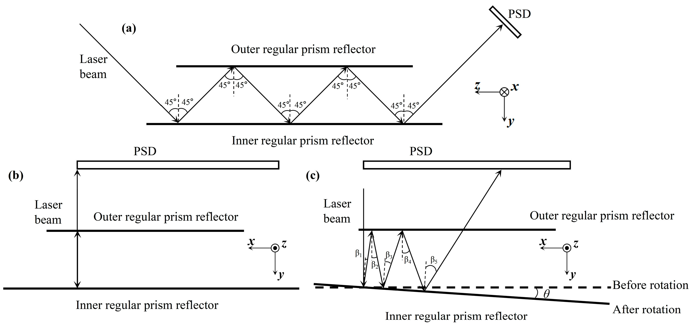
Figure 1. Angle amplification principle of a laser with multiple reflections. (a) The laser has an incident angle of 45°, and the inner and outer regular prism reflectors are parallel. (b) The laser is normally incident on the inner regular prism reflector, and the inner and outer regular prism reflectors are parallel. (c) The laser is normally incident on the inner regular prism reflector, and the inner regular prism reflector is deflected by θ.
Photonics 12 00890 g001
Figure 2. Schematic diagram of the angle measurement principle, with the red arrow indicating the trajectory of the measurement Laser, (a) when the inner and outer reflectors are parallel; (b) when the inner reflector is rotated by a small angle θ.
Photonics 12 00890 g002
Figure 3. (a) Schematic diagram and (b) physical diagram of the sensor mechanical structure.
Photonics 12 00890 g003
Figure 4. Physical diagram of the sensor system.
Photonics 12 00890 g004
Figure 5. (a) The measurement data of the laser interferometer and sensor system; (b) the error data between the laser interferometer and sensor system.
Photonics 12 00890 g005
Figure 6. (a) Measurement datasets from the 6× extended optical-lever sensor baseline; (b) corresponding error distributions.
Photonics 12 00890 g006
Figure 7. (aj) Measurement datasets and corresponding error distributions of the dual-unit alternating measurement strategy.
Photonics 12 00890 g007
Disclaimer/Publisher’s Note: The statements, opinions and data contained in all publications are solely those of the individual author(s) and contributor(s) and not of MDPI and/or the editor(s). MDPI and/or the editor(s) disclaim responsibility for any injury to people or property resulting from any ideas, methods, instructions or products referred to in the content.