1. Introduction
With continuous advancements in aerospace technology, inter-satellite laser communication has become an important research direction in the field of high-speed information transmission in space. Compared with microwave-based GNSS components, laser ranging shows higher performance in precision and contributes to improved orbital models of satellites. The precision of laser ranging and the stability of laser communication demand rapid establishment and long-term stabilization of inter-satellite laser links (ISLLs).
The divergence angle of a laser beam used in satellite laser communication is usually on the order of tens of microradians, and the extremely narrow beam alignment requires the laser terminal involved in ISLLs to have pointing and tracking accuracies on the order of microradians [
1,
2,
3,
4,
5,
6,
7,
8,
9,
10,
11]. Since the two satellites involved in inter-satellite laser communication move relative to each other at a distance of thousands or even tens of thousands of kilometers, an inevitable transmission delay between them arises during laser beam transmission and reception. During this period, the laser terminals at both ends move along their respective flight orbits, generating a certain relative distance and angle. In order to maintain accurate laser ranging, stable tracking, and continuous communication of the laser link during this dynamic movement process, the transmitting end must accurately predict the additional movement angle caused by the bidirectional transmission delay of the beam in advance, according to the direction of the received beam. Then, the transmitting laser beam can target the predicted position of the receiving end to ensure accurate communication [
11,
12,
13]. The laser beam emitted by the transmitting end is a Gaussian beam. The transmitting end will introduce a large additional pointing loss when the deviation of the PAA is too large, resulting in the deterioration of the link performance and the interruption of tracking or the communication link. Hence, in order to realize accurate laser ranging, stable tracking, and continuous communication of the laser link between satellites, the laser terminal needs to accurately predict the point-ahead angle, accounting for the delay in the relative movement of the two ends, and adjust the direction of the transmitting laser beam by loading the driver to control the advanced pointing lens through software.
At present, some research relevant to the estimation algorithms and ground test methods of the point-ahead angle of ISLLs has been carried out [
12,
13,
14,
15,
16,
17]. As early as 1977, McElroy et al. proposed that the point-ahead angle of the geosynchronous equatorial orbit (GEO)–GEO laser link and the low Earth orbit (LEO)–GEO laser link were 40 μrad and 70 μrad, respectively, but no calculation method was given [
12]. In recent years, Wang et al. presented an advanced point-ahead angle measurement method in 2017 and conducted experimental verification, with a measurement accuracy of less than 1 μrad [
13]. In 2020, Gerard et al. proposed a calculation method for the point-ahead angle of the GEO-GEO laser link and the LEO-GEO laser link. However, this method cannot calculate the point-ahead angle of an LEO-GEO laser link in real time [
14]. In 2020, Zhang et al. studied a prediction method of the point-ahead angle based on the Kalman filter algorithm, and the maximum prediction error is 3.8 μrad [
15]. In 2022, Shao et al. studied the algorithm for the point-ahead angle based on movement information fusion. The experimental results showed that the accuracy of the proposed method was better than 0.1 μrad under the working conditions of using very short arc optical data for orbit determination [
16]. In the same year, Lazzaro et al. evaluated the possibility of accurately estimating the PAA in advance using the TLE (two-line element) sets for the orbiting satellite and found that the maximum error observed between the estimated and measured PAAs was less than 1 μrad, demonstrating the possibility of this point-ahead correction technique for LEO orbiting satellites [
17]. In 2023, Wang et al. put forward a tracking compensation method for the point-ahead angle, but only completed simulation verification using MATLAB 2022 without obtaining actual on-orbit experimental verification [
18]. In summary, the calculation results of the above-mentioned point-ahead angle estimation methods have not been verified in orbit, and the correctness and accuracy of the proposed algorithm cannot be evaluated.
In this work, a real-time and high-precision point-ahead angle algorithm was proposed and verified to accurately predict the point-ahead angle of ISLLs. Based on the spatiotemporal body coordinate rotation relationship between local and target satellites, the temporal variation in the azimuth and elevation components of the point-head angle can be accurately calculated, combined with the definition of the point-head angle and the angle projection relationship. This algorithm does not require additional filtering calculations and achieves higher prediction accuracy with less satellite computational resources. First, to verify the correctness of the proposed algorithm, the maximum point-ahead angles of typical GEO-GEO and LEO-GEO links were simulated and compared with the results in the existing literature. Then, based on an actual engineering application of ISLLs, the algorithm was used to simulate the temporal variation in azimuth, elevation, and synthetic point-ahead angles. The simulation results were analyzed and compared with on-orbit experimental results. The deviation between the calculations and the on-orbit experimental results was on the order of nanoradians, and the calculation accuracy was improved by three orders of magnitude compared with the existing literature (μrad). The algorithm proposed in this manuscript can be applied to the prediction of PAAs of various inter-satellite laser links in medium, low, and high orbits, with a wide application range and strong universality.
2. Basic Principle and Algorithm
The principle of the real-time high-precision point-head angle prediction algorithm is described in this section. As shown in
Figure 1, in the laser link established between satellite S and satellite M, the transmitting angle of the laser beam emitted by the laser terminal on satellite S needs to follow the moving direction of satellite M to compensate for the point-ahead angle caused by the relative displacement of the two ends of the beam within the propagation time from
t0 to
t2.
represents the direction of the signal from satellite M received by satellite S at time
t1.
represents the direction of the signal transmitted by satellite S at time
t1. The angle
β between
and
is the point-ahead angle of the ISLL.
In
Figure 1, the position of satellite S in the J2000 coordinate system is denoted as
p(
xJ,
yJ,
zJ), and the velocity is denoted as
v(
vJx,
vJy,
vJz). For a three-axis stabilized satellite S, the origin of its body coordinate system is taken from the center of mass of the satellite, where
Xs is the rolling axis,
Ys is the elevation axis, and
Zs is the yawing axis. When the flight attitude angle of the satellite is 0, the body coordinate system of the satellite coincides with the centroid orbit coordinate system. In this case, the coordinates
δrJ(
xJ,
yJ,
zJ) under the inertial ordinate system can be converted to the coordinates
δrs(
xs,
ys,
zs) under the centroid orbit coordinate system, and the conversion relationship can be expressed as:
where
LX and
LZ are the rotation matrices rotating around
XJ and
ZJ, respectively [
19];
u is the argument of latitude in the satellite Kepler-orbit parameters, which is equal to the sum of the argument of perigee
ω and the true anomaly
f;
i is the inclination of the satellite orbit, Ω is the right ascension of the ascending node, and
LOO1 is the inverse matrix of coordinate axes.
As can be seen from
Figure 1, under the body coordinate system of satellite S,
points to the forward direction of satellite S, in other words, to the direction of the velocity
.
always points to the Earth’s core, that is, to the origin 0
J of the J2000 coordinate system. According to the magnitude
of the position vector
and the magnitude
of the velocity vector
at time
t, the rotational angular velocity ω of satellite S under its body coordinate system can be expressed as:
Under the body coordinate system of satellite S, the position of satellite M is denoted as M(
xi,
yi,
zi,
ti). In this case, the target vector
from satellite S to satellite M at
t1 can be expressed as
r1(
x1,
y1,
z1), and the target vector
from satellite S to satellite M at
t2 can be expressed as
r2(
x2,
y2,
z2). According to Equation (2), it can be calculated that in the period Δ
t =
t2 −
t1, the rotation angle
θ of satellite S under its body coordinate system can be expressed as:
To obtain the point-ahead angle
β of satellite M at
t1 relative to satellite S, the coordinates of satellite M at
t2 r2(
x2,
y2,
z2) should be converted into the body coordinate system of satellite S at
t1 (
,
,
). According to the rotation relation of the coordinate systems and Equation (3),
,
,
can be expressed as:
At
t1, the azimuth angle
A1 and elevation angle
E1 under the body coordinate system of satellite S can be expressed as:
At
t2, the azimuth angle
and elevation angle
under the body coordinate system of satellite S can be expressed as:
Thus, in the period Δ
t =
t2 −
t1, the azimuthal angular velocity
and the elevation angular velocity
of the target vector under the body coordinate system of satellite S can be expressed as:
According to the definition of the point-ahead angle, the bidirectional transmission delay can be approximated as twice that of the unidirectional transmission delay. Thus, the azimuth component
βA, elevation component
βE, and the total
β of the point-ahead angle can be expressed by using the azimuth and elevation components as:
where
c is the speed of light in vacuum.
3. Simulation Results
Two typical ISLL scenarios, namely the GEO-GEO link and the LEO-GEO link, were selected to verify the correctness of the point-ahead angle estimation algorithm proposed in this work.
- (1)
Simulation results of the point-ahead angle of the GEO-GEO link
For the GEO-GEO link, two GEO satellites are in the same circular orbit above the equator. According to the spatial position relationship between the two satellites, the point-ahead angle
β of the GEO-GEO ISLL can be calculated by using the spatial position with the following equation:
where
VT1 and
VT2 are the tangential components of the orbital speeds of the two satellites [
12,
13].
The rotational angular velocity ωGEO and the altitude R0 of a geosynchronous Earth orbit satellite are equal to 7.287 × 10⁻⁵ rad/s and 35,786 km, respectively. The radius of the Earth RE is equal to 6378 km. α is the angle between the center of the Earth between the two GEO satellites, and c is the speed of light in vacuum. It can be seen from Equation (14) that for a fixed α, the point-ahead angle of the laser link between two GEO satellites is a fixed value.
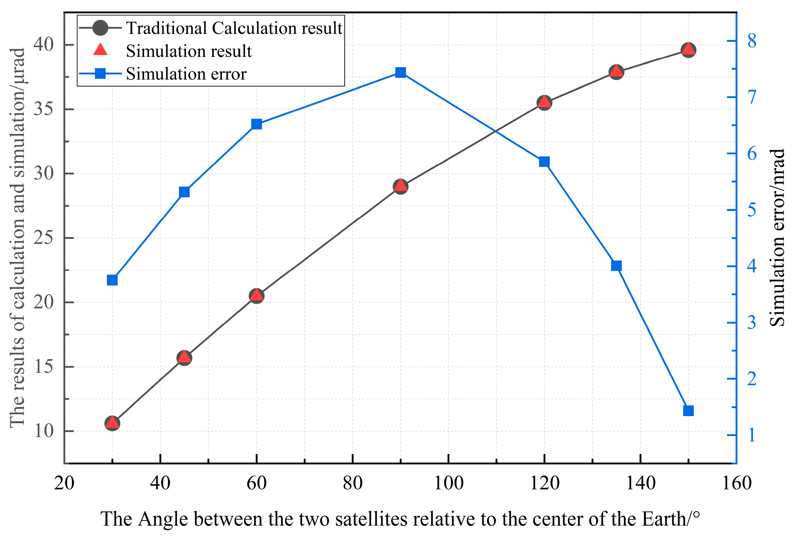
Figure 2 shows the simulated point-ahead angle results and the corresponding errors when the geocentric angle
α is set to be 30°, 45°, 60°, 90°, 120°, 135°, and 150°, respectively. As shown in
Figure 2, with the increase in
α, the point-ahead angle of the GEO-GEO ISLL increases. Specifically, when the geocentric angle
α is 30°, the simulated point-ahead angle
β is 10.610 μrad, and when the geocentric angle
α is 120°, the simulated point-ahead angle
β is 35.502 μrad. For better comparison, the calculated curve of the relation between the point-ahead angle
β and the geocentric angle
α obtained from traditional Equation (14) is also given in
Figure 2. Therefore, by comparing and analyzing the results obtained by Equation (14) and the algorithm proposed in this paper, the estimation error of the proposed algorithm is less than 7.5 nrad.
- (2)
Simulation results of the point-ahead angle for the LEO-GEO link
For the LEO-GEO ISLL, the two satellites are located in different orbits. According to the spatial relationship between the two satellites, it can be known that when the LEO satellite crosses the equatorial plane, the relative speed between them reaches a maximum. Therefore, the point-ahead angle
β of the LEO-GEO ISLL can be calculated by the following equation:
where
h and
i are the orbital altitude and inclination of the LEO satellite, respectively [
12,
13];
ωGEO and
ωLEO are the rotational angular velocities of the GEO and the LEO satellites, respectively. The geocentric gravitational constant
μ is equal to 3.986 × 10
14 m
3/s
2.
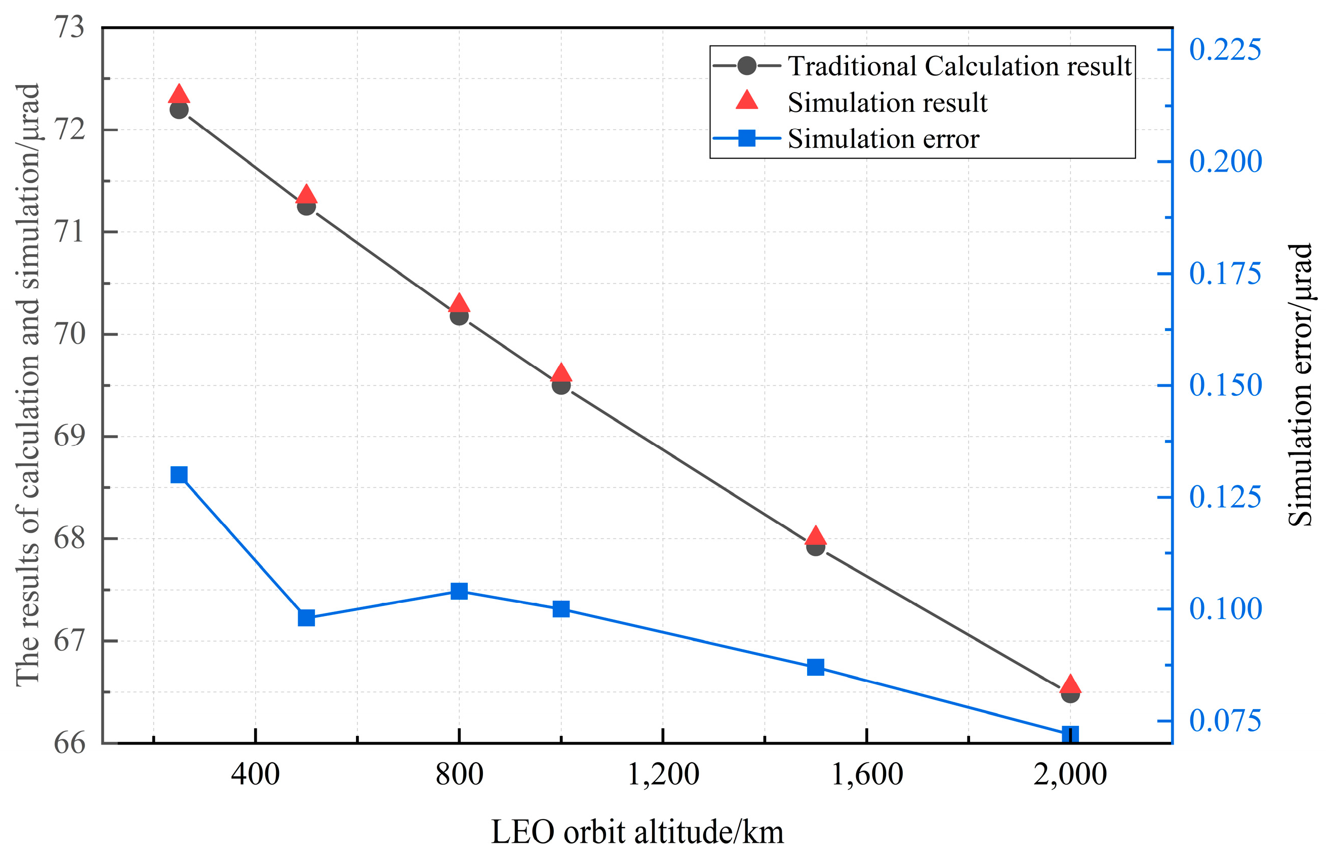
Figure 3 shows the simulated point-ahead angle results and the corresponding errors when the orbital inclination
i is fixed at 0° and the orbital altitude
h is set to be 250 km, 500 km, 800 km, 1000 km, 1500 km, and 2000 km. As shown in
Figure 3, with the increase in
h, the point-ahead angle of the LEO-GEO ISLL decreases. When the orbital altitude
h is 250 km, the calculated maximum point-ahead angle
β is 72.329 μrad, and when the orbital altitude
h is 2000 km, the simulated maximum point-ahead angle
β is 66.556 μrad. By comparing and analyzing the results obtained by traditional Equation (15) and the algorithm proposed in this paper, the estimation error of the proposed algorithm is less than 0.15 nrad.
5. Discussion
To maintain the stability of the ISLL, the PAA calculation error needs to be eliminated. Compared with other traditional calculation method (μrad and sub-μrad accuracy), our method shows higher performance (nrad accuracy) in precision and is more suitable for multiple scenarios such as GEO-GEO, GEO-LEO, and LEO-LEO [
13,
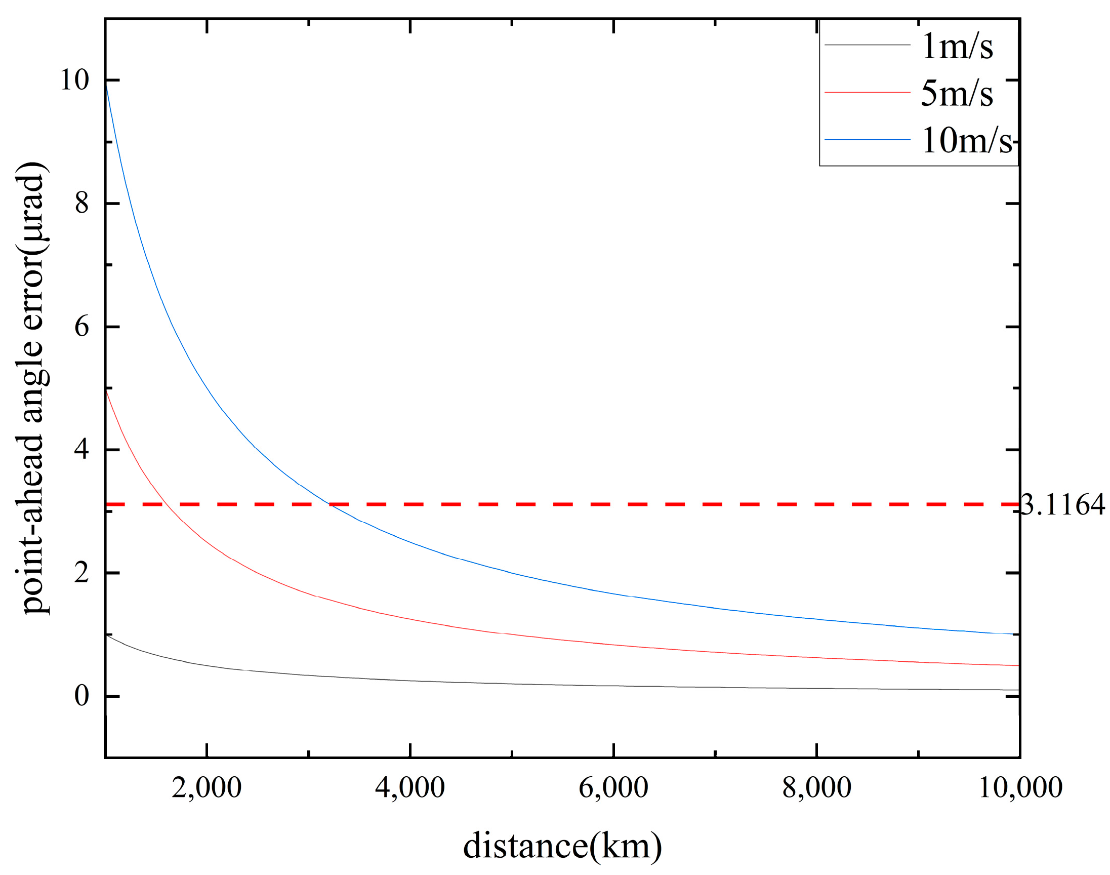
15]. Apart from the calculation error, the PAA error is also affected by the orbital recurrence accuracy. When the inter satellite distance is 10,000 km, a 1 m/s orbital recurrence accuracy will result in a pointing error of 100 nrad, as shown in
Figure 9. When the distance becomes larger, the calculation accuracy of PAA has a greater impact on the PAA error. Therefore, improving the accuracy of the PAA is of great significance for the establishment and stability of the ISLL. In addition, for engineering applications, the higher the link stability, the higher the requirement for the PAA accuracy. Therefore, high PAA accuracy can provide engineering reserves for the long-term application of the ISLL. Meanwhile, the accuracy of the PAA is a crucial parameter used to characterize the ranging accuracy, in which improving the accuracy of PAA is also important for enhancing the measurement accuracy.
6. Conclusions
High-precision aiming is one of the most important preconditions for laser ranging and long-term link stabilization among satellites. Therefore, the transmitting end must accurately predict the point-ahead angle caused by the transmission delay according to the orbital information of both ends in advance and compensate for it in real time.
Given the requirements for laser ranging and establishing ISLLs, a point-ahead angle estimation algorithm is studied in this work, aiming to solve the problem of real-time compensation for the point-ahead angle of the laser link. Simulation and experimental verification were carried out based on typical on-orbit scenarios. The verification results show that the proposed algorithm is characterized by high precision, while the measurement error of laser ranging is less than 50 μm. The algorithm can meet the real-time prediction requirements of various ISLLs, such as GEO-GEO. In addition, the algorithm has a simple calculation process and low resource consumption. It has significant practical value in improving the measurement accuracy, aiming performance, and link stability of ISLLs and can be widely promoted and applied in inter-satellite laser communication.

