1. Introduction
The narrow-linewidth lasers have attracted widespread attention due to their tremendous potential in high-precision coherent detection and related fields [
1,
2,
3,
4,
5,
6]. Among the ways of narrow linewidth laser, self-injection locking (SIL) has been recognized as an effective technique for achieving narrow-linewidth laser [
7,
8]. This approach involves re-injecting the reflected or scattered light from a high-Q micro-resonator back into the laser cavity, thereby locking the laser’s emission frequency to the resonance frequency of the external cavity. This frequency-locking mechanism not only significantly compresses the laser linewidth but also improves the frequency stability and coherence of the laser, making it highly valuable for applications in high-precision optical measurements, laser communications, and optical frequency combs’ generation.
Among the configurations of SIL, semiconductor laser diodes are widely regarded as the excellent light sources for hybrid integration with micro-cavities and self-injection locking, owing to their compact size, low cost, and compatibility with on-chip photonic integration. For example, researchers have injected the output light of semiconductor laser diodes into high-Q micro-ring resonators [
9,
10,
11,
12,
13,
14]. However, in these previous studies, there were only high-Q filters typically used to extract specific modes from the multi-mode laser and feed them back into the cavity to establish narrow linewidth single-longitudinal-mode (SLM) oscillation. These approaches could not offer enough photon lifetime to the diode cavity and thus make the laser linewidth broaden and decrease the laser’s coherence.
In this study, we propose a self-injection locking laser based on a hybrid feedback scheme, which integrates a semiconductor gain chip with a grating external cavity and micro-ring resonator (MRR). The employing of the grating external cavity effectively extends the optical cavity length of the laser while providing feedback light with long photon life. In addition, a high-Q MRR is integrated at the rear of the laser as a negative feedback element, which further increases the photon lifetime and effectively benefits SLM operation and suppresses mode hopping. Benefiting from the synergistic effects of both the grating external cavity and the micro-ring resonator feedback, the laser ultimately achieves high side-mode suppression ratio (SMSR) and ultra-narrow linewidth performance.
2. Principle
Figure 1 illustrates the fundamental principle of our designed narrow-linewidth laser with a high coherence and SMSR output. The design of our narrow-linewidth SIL lasers first relies on using the external cavity to increase the photon lifetime and narrow linewidth, as shown in the structure of
Figure 1a. In
Figure 1a, the upper modes represent the resonant modes of the external cavity, typically realized by an MRR or a Fabry–Pérot (FP) resonator, while the lower modes correspond to the resonant modes of the free-running laser cavity. By tuning the temperature, the resonant frequency of the external cavity can be adjusted. Since the free spectral range (FSR) of the MRR differs from that of the laser cavity, the Vernier effect can be exploited to finely align the external cavity resonance with that of the laser. As a result, within a certain gain bandwidth, only one resonant frequency of the laser cavity coincides with that of the external cavity. Consequently, the laser oscillates at a single frequency, thereby achieving stable SLM operation. However, because of the long optical length of the feedback, the resonator bandwidth could not choose only one mode of the external cavity. The laser spectrum could be a multi-mode operation, which limits the coherence of the laser. To overcome this limitation and its influence on the coherence, we have designed a hybrid optical feedback scheme aimed at achieving both high coherence and high SMSR simultaneously. As shown in the structure of
Figure 1b,c, the colored curves represent the gain spectrum of the laser, while the light-blue curves denote the output spectra of the laser under different feedback configurations. As shown in the structure of
Figure 1b, this design first introduces an external cavity formed by a fiber Bragg grating (FBG). By employing the external cavity feedback light provided by the FBG, the support for the main lasing mode is significantly enhanced; with the long length of the external cavity, the photon lifetime could be increased. Moreover, as shown in
Figure 1c, a high-Q MRR is incorporated at the rear end of the laser as a self-injection locking feedback element, which provides selective feedback through its resonance characteristics and further compresses the laser linewidth. Such feedback light enables linewidth compression of the laser through the self-injection locking mechanism. Then we realized a laser that simultaneously achieves ultra-narrow linewidth and SLM output.
To achieve high coherence SLM emission, an FBG is first used as an external cavity. Since the reflection spectrum of the FBG contains multiple resonant modes of the laser, the laser output may still operate in multi-modes without any tuning. However, the various resonant modes within the FBG transmission through the MRR for SIL. By using the vernier effect, the multi-modes of the laser could only have one mode match the resonance frequency of the MRR. Thus, the SIL feedback spectrum contains only one mode of laser cavity. Then, we can align a single mode of the laser to match the center frequency of the MRR resonance by adjusting the MRR temperature, as illustrated in
Figure 1. At this point, this mode can achieve lasing and suppress oscillation of other resonant modes, thereby producing SLM laser output.
Meanwhile, to accommodate a high-effective external cavity feedback system and further compress the linewidth of the laser, we introduced a self-injection locking feedback system at the rear facet of the laser diode. The light can be coupled into a micro-ring resonator via the straight waveguide through the back end of the SOA. To further narrow the linewidth compression of the laser, as illustrated in
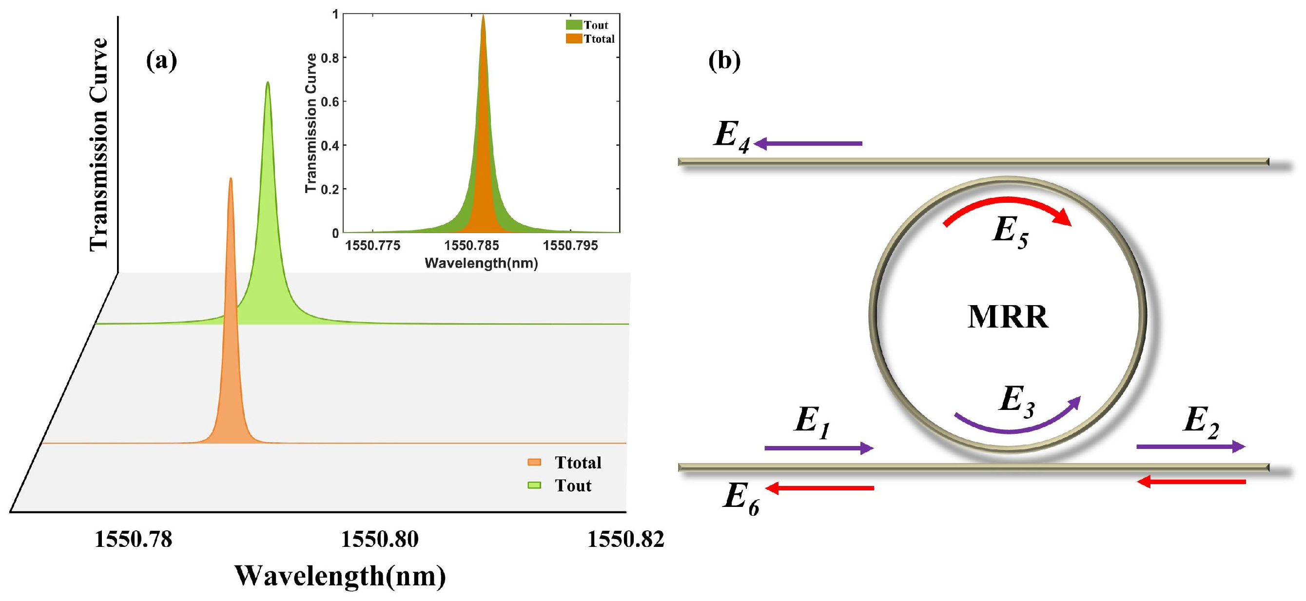
Figure 2b, the feedback light E
1 at the output end of the SOA in our design passes through an add-drop type micro-ring resonator as E
3. The E
4 is reflected and then, becoming E
5, passes through the micro-ring resonator again before being fed back into the laser for self-injection locking. Compared with previous designs, in our configuration, the laser light passes the micro-ring resonator twice. This approach has been thoroughly investigated by researchers [
15], and it can significantly improve the filtering capability of the micro-ring resonator. First, after a single roundtrip through the micro-cavity, the optical field transmission coefficient at the drop port can be expressed as follows [
16]:
The transmission coefficient of the upper coupling area is
. The transmission coefficient of the lower coupling area is
. The transmission coefficient in the MRR is
and R is the radius of the MRR. In the experiment, we use a fiber mirror to make the beam of the drop port transmit to the MRR again and then inject it into the laser for SIL. The selected optical mode passes through the MRR twice, and this effect enhances the frequency selectivity of the MRR for the laser. This is beneficial for improving the frequency discrimination capability of the MRR in the self-injection locking system, thereby further reducing the linewidth of the laser output.
In
Figure 2a, we make the transmission curve of the different MRR settings. For parameters of MRR, we take
is 99.96% and
is 99.96%. The
is 1 and the radius R is 620 um. The green solid line represents the transmission curve of MRR, and the orange solid line represents the transmission curve of passing twice of MRR. It can be seen that after passing through the MRR twice, the optical field fed back into the laser cavity exhibits a narrower spectral profile, thereby achieving higher frequency selectivity. In the self-injection locking, this could improve the locking performance of SIL [
17,
18,
19].
To analyze and describe the self-injection locking of the MRR, we established a simplified model of self-injection locking. The model includes the output laser frequency, the free-running laser frequency, and external cavity parameters. The relationship among the parameters could be written as follows [
20]:
where
is the free-running laser frequency and
is the laser frequency under a self-injected locking state.
is ratio of the injected feedback power to the output laser power.
and
are photon round trip time in the laser cavity and total feedback delay time.
represents the linewidth enhancement factor. The B corresponds to the transmission of the locking cavity. The transmission rate of the ‘drop’ port of the MRR could be described by Equation (1). And the transmission rate of the re-injection configuration could be described by Equation (2).
Based on the aforementioned expressions and the specific parameters provided in the manuscript, we plotted the self-injection locking tuning curves for the two different configurations. As shown in
Figure 3a, it can be observed that, although the single-pass self-injection locking system exhibits a wider locking range, the double-pass self-injection locking system demonstrates a significantly flatter locking curve. This flatter response implies that, when the free-running frequency of the laser experiences fluctuations, the output frequency in the double-pass configuration remains more effectively stabilized to the resonance frequency of the MRR.
From a theoretical perspective, the flatter tuning curve corresponds to a stronger frequency discrimination effect within the self-injection locking, which enhances the system’s ability to suppress frequency deviations and stabilize the laser emission. Therefore, the double-pass self-injection locking system offers superior locking performance, ultimately enabling more efficient linewidth compression and improved spectral purity of the laser output.
Moreover, to calculate the improvement of the re-injection, we introduce the noise reduction factor (NRF) to evaluate the SIL linewidth compression [
17,
18]. The NRF could be described as the ratio of the laser-MRR frequency and the output frequency of the laser, which could be written as follows:
As shown in
Figure 3b, compared with the self-injection locking configuration based on an MRR, the re-injection configuration exhibits an enhanced NRF at the selected mode. Specifically, while the maximum NRF achieved by the single injection is 4667, corresponding to 36.7 dB, the re-injection improves this to 7836, which corresponds to 38.9 dB. This indicates that the laser noise can be suppressed by roughly 38.9 dB with the re-injection configuration. A higher NRF corresponds to stronger frequency locking capability, thereby confirming that the re-injection offers superior locking performance compared to the single-based SIL approach.
This improvement stems from the re-injection ability to narrow the spectral width of the selected mode, effectively increasing the cavity’s quality factor (Q-factor). This higher Q-factor enables more efficient self-injection locking and contributes to further linewidth compression of the output laser.
3. Experimental Results and Discussion
Our laser system is illustrated in
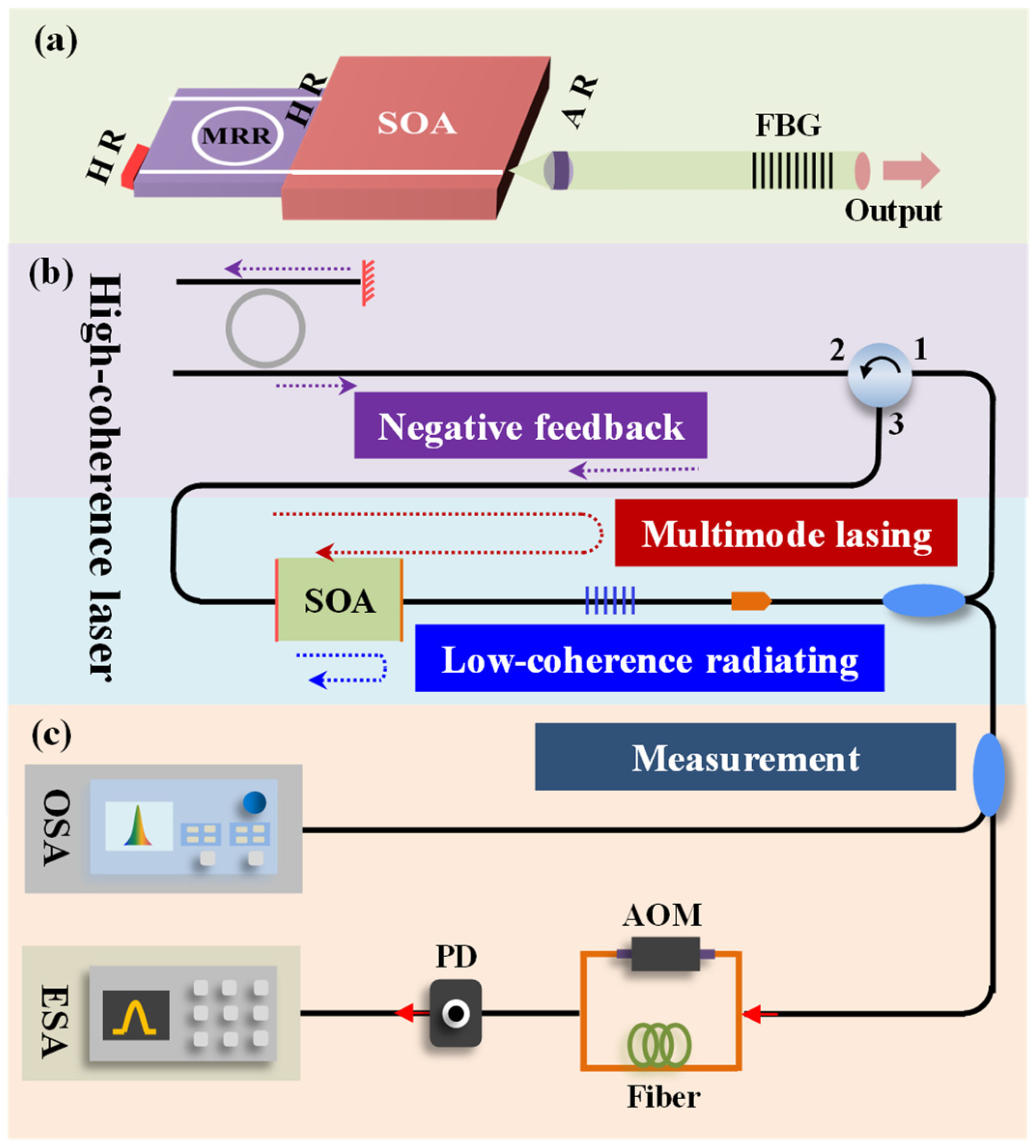
Figure 4.
Figure 4a depicts the conceptual design of the hybrid feedback laser. The laser works with an InP-based SOA, an FBG, and an MRR chip. The SOA has two reflective facets for the laser oscillation. Without the external cavity, the laser diode has a multi-mode output. The AR port of the SOA connects to the FBG for output and high-photon lifetime feedback. The HR coat has a 95% reflectivity connecting the MRR. The MRR has an HR coat for enabling the light of the drop port to inject into the MRR twice, which is called re-injection architecture. To prevent the back reflections into the laser diode, the SOA chip and the fiber array were polished at an angle of 8 degrees. The FBG has a length of 100 mm, and this can benefit the enhancement of the photon lifetime, thereby narrowing the linewidth of the laser output. The FBG provides a reflectivity of 90% with a narrow bandwidth of 0.19 nm, with a center wavelength of 1550.11 nm. The experiment configuration of the hybrid feedback laser is shown as
Figure 4b. The laser diode with reflective facets operates with multi-mode lasing and low-coherence radiating. The FBG could make the mode in its limited bandwidth of the spectrum and feedback to the diode for enhancing the photon lifetime. Then the output beam is separated for SIL and measurement. By employing the optical circulator and the optical fiber mirror, the injection beam of the MRR could be re-injected into the MRR. With a narrower bandwidth of the light, then the feedback light to the diode could make the laser linewidth effectively narrow. Because of the only one mode reflective beam of MRR, the laser diode could switch to the SLM operation effectively.
The on-chip MRR in the back facet of the laser is fabricated on a high-index silica glass platform compatible with complementary metal-oxide-semiconductors (CMOS) [
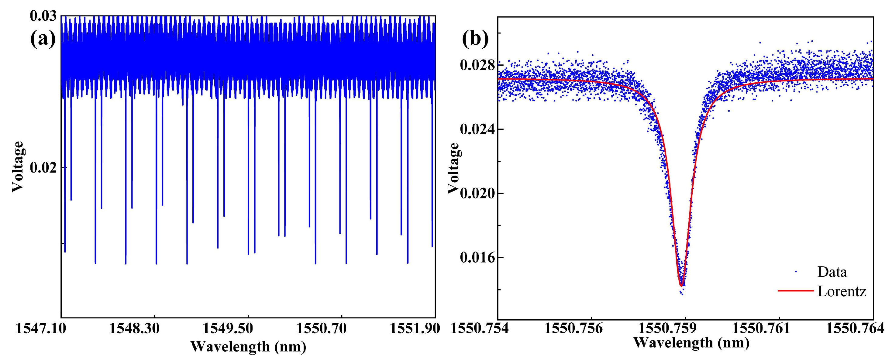
21]. The refractive index of the waveguide core is 1.6, and the cross-section is 2 × 3 µm. The radius of the MRR is about 620 µm, corresponding to a free spectral range of 48.25 GHz.
Figure 5a shows the optical transmission curve of the MRR at the drop end of the waveguide, and
Figure 5b shows one of the enlarged curves, with a 3 dB spectral width of 0.6 pm and a corresponding Q factor of 2.5 × 10
6. The micro-cavity adopts an add-drop configuration, with a reflector fiber mirror added at the drop port, thereby modifying the resonant characteristics of the laser cavity. The through port corresponding to the drop port serves as a monitoring point to detect the detuning between the laser frequency and the micro-cavity resonance.
The initial FP laser is formed by an SOA with coatings on both facets, producing multi-longitudinal-mode laser output. The FBG could improve the length of the laser cavity, which is crucial for enhancing the coherence of the laser. By introducing the filtered feedback from an MRR with selective high reflectivity characteristics, the longitudinal mode structure of the laser can be controlled. First, without tuning and SIL feedback, the output modes of the FP laser may be distributed on both sides of the FBG reflection spectrum. Since the various longitudinal modes experience similar and relatively low gain, the laser operates in an unstable multi-longitudinal-mode oscillation state with the modes’ competition. For high precision of tuning, we consider locking the temperature of the MRR and tuning the laser current to control the detuning between MRR resonance and the laser frequency. As shown in
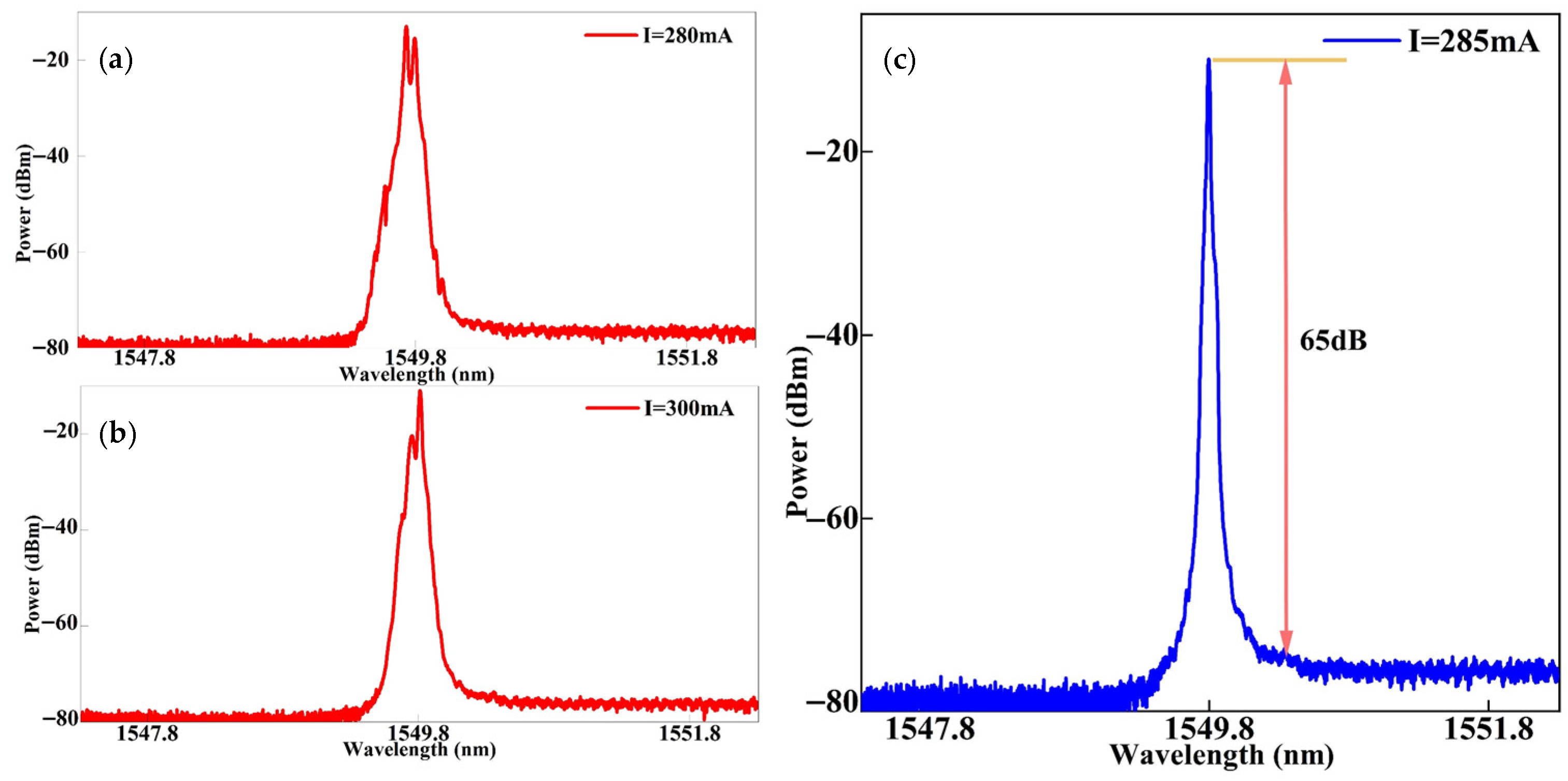
Figure 6, when the current is set to 280 mA, the laser operates in a multi-longitudinal-mode regime, where gain competition between different wavelengths results in an unstable spectrum with multiple longitudinal modes. When the laser current is tuned to 300 mA, the laser exhibits a dual-longitudinal-mode operation. This occurs because light at two frequencies simultaneously achieves sufficient gain while suppressing oscillation of other modes. However, the gain at the higher-power wavelength is insufficient to cause a significant drop in the gain at the lower-power wavelength, ultimately leading to a dual-wavelength output. Finally, at a current setting of 285 mA, one resonant mode of the FP laser aligns in frequency with the SIL cavity mode of the MRR, resulting in maximum feedback power of all the modes. This causes the laser output to switch to single-longitudinal-mode (SLM) operation, where only one longitudinal mode remains dominant while all other competing modes are effectively suppressed. Furthermore, under single-mode conditions, the presence of strong optical feedback plays a critical role in stabilizing the lasing process. The intense feedback selectively enhances the gain for the desired lasing mode while simultaneously imposing additional losses on adjacent resonant modes. As a result, the gain experienced by these neighboring modes is rapidly reduced, causing their output power to drop significantly. This strong mode discrimination ensures that unselected modes contribute negligibly to the laser output, thereby significantly improving the side-mode suppression ratio (SMSR) and thus enhancing the coherence of the laser. At a current of 285 mA, the laser output power reached 14.9 mW, achieving a relatively high and satisfactory level.
To further narrow the laser’s linewidth, we implemented a self-injection locking design where the locking light traverses the micro-ring resonator twice before injecting back into the FP cavity, enhancing its frequency selectivity as detailed earlier. By introducing backward-injected locking light, the laser receives narrow-bandwidth optical feedback. This feedback light is beneficial for compromising the frequency stability of the laser output and also helps to further narrow the linewidth and improve the coherence of the emitted laser. The optical power measured at the monitoring port reflects the amount of optical field energy stored within the micro-ring resonator. As the temperature of the MRR is tuned, the resonance frequency of the micro-ring shifts, thereby altering the frequency detuning between the laser and the MRR. According to the theory of self-injection locking, when the laser frequency matches the resonance frequency of the MRR (the detuning is zero), the self-injection locking effect reaches its optimum, resulting in maximal frequency stabilization and linewidth compression. Consequently, by thermally tuning the micro-cavity such that the detuning approaches zero, the laser achieves its best locking performance. Furthermore, the optical power measured at the monitoring port serves as an effective indicator of the detuning: a higher monitored power corresponds to greater intracavity stored energy and smaller detuning. Therefore, when temperature tuning leads to the maximum monitored power, the laser is optimally locked to the micro-ring resonance, and the self-injection locking effect is fully realized [
22,
23,
24]. To finely tune the frequency detuning between the laser output and the micro-ring resonance, we employ a high-precision thermoelectric cooler (TEC) capable of controlling the micro-cavity temperature with an accuracy of 0.01 °C. By adjusting the micro-cavity temperature with precision, the resonance frequency of the micro-ring can be shifted accurately. This thermal tuning allows the precise control over the spectral alignment between the laser emission and the resonant peak of the micro-ring, ensuring optimal conditions for self-injection locking. Once the system reaches the condition where the optical power at the monitoring port is maximized, indicating that the laser frequency is well aligned with the micro-ring resonator, temperature tuning is halted. At this point, the laser output is stably locked to the resonance frequency of the micro-ring resonator, effectively enabling significant linewidth reduction. This stable locking not only compresses the laser linewidth but also improves the frequency stability and spectral purity of the emitted light, which is crucial for applications requiring high coherence and narrow spectral features.
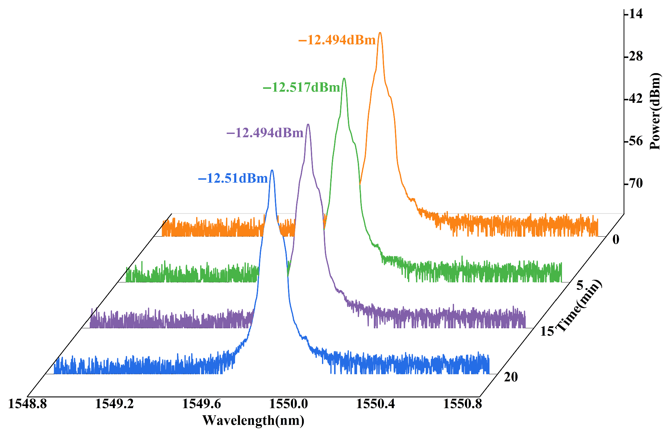
To evaluate the stability of the laser output, we conducted a continuous monitoring test lasting 15 min, during which data were collected at 5-min intervals, as illustrated in
Figure 7. The results show that the SLM characteristic, central wavelength, and output power of the laser remained nearly unchanged at 0, 5, 10, and 15 min, indicating good operational stability. Furthermore, to further enhance stability, the laser could be packaged in a sealed box with improved temperature control of the associated components.
Under self-injection locking conditions, the laser linewidth was measured using the Delayed Self-heterodyne Interferometry (DSHI) method [
25,
26], as illustrated in
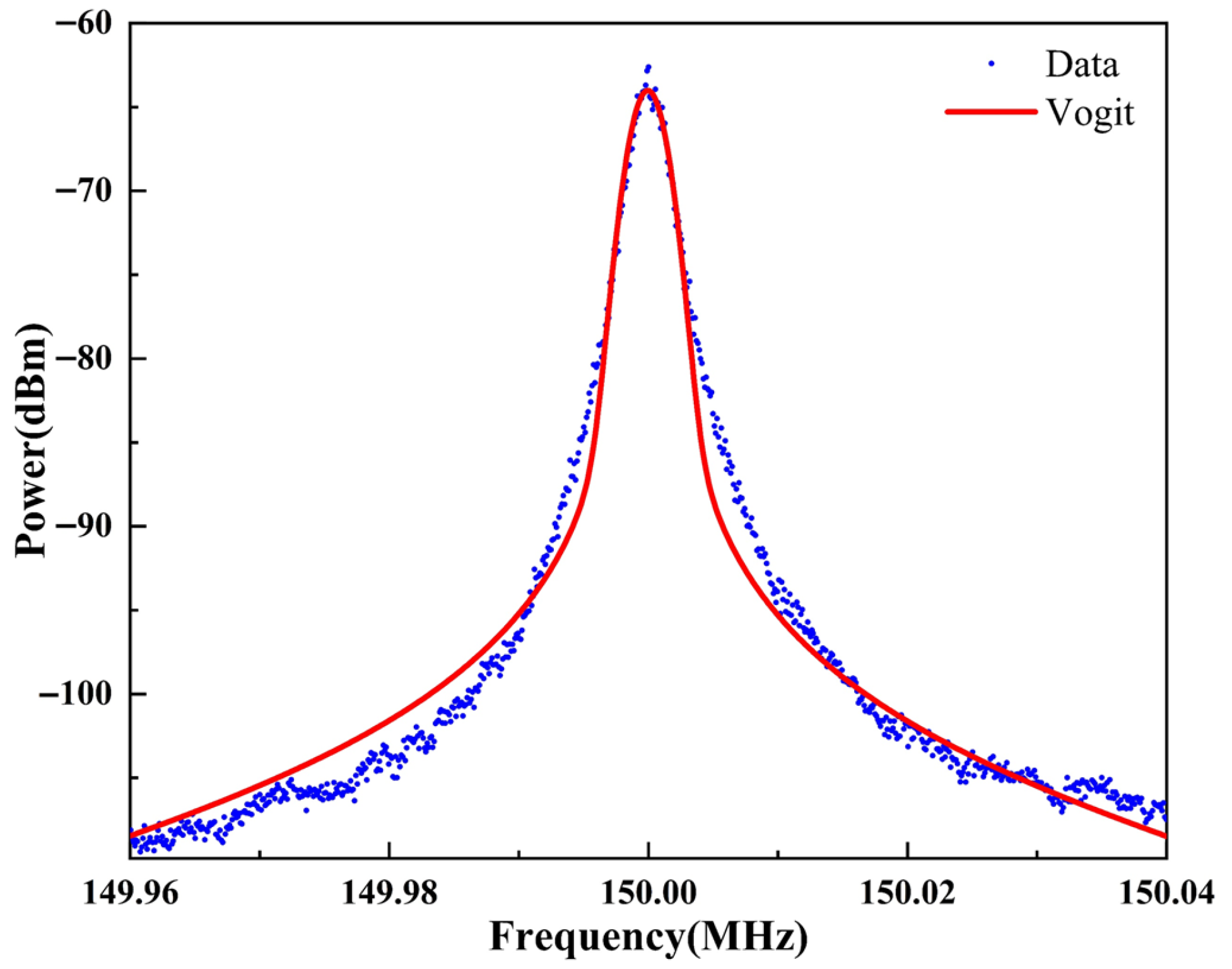
Figure 4c. In this setup, the laser output is split into two optical paths. One path passes through an acousto-optic modulator (AOM) operating at a center frequency of 150 MHz, introducing a frequency shift to prevent signal overlap near DC in the detected spectrum. The other path travels through a 25 km long optical fiber, introducing a significant time delay between the two beams. After traversing their respective paths, the two beams are recombined and directed onto a photodetector, where they interfere and produce a beat signal at the AOM frequency. This electrical signal is then analyzed using an electrical spectrum analyzer to characterize the laser’s spectral properties. The measured spectrum displays a profile influenced by two primary mechanisms. Firstly, Lorentzian broadening arises from the laser’s intrinsic phase noise, representing the fundamental linewidth due to spontaneous emission and cavity dynamics. Secondly, Gaussian broadening results from low-frequency 1/f noise introduced predominantly by the long delay fiber in the measurement setup. This Gaussian contribution causes the measured optical power spectrum to deviate from an ideal Lorentzian shape, complicating precise linewidth extraction. As shown in
Figure 8, to accurately separate these effects, we employed a Voigt profile fitting method to model the measured spectrum as a convolution of Lorentzian and Gaussian components. From this fitting, we determined that the Lorentzian linewidth of the laser was 149 Hz, while the Gaussian contribution was measured at 2649 Hz. It is important to note that the Gaussian broadening is primarily an artifact of the measurement system—stemming from excess noise introduced by the long fiber delay—and does not reflect the intrinsic spectral purity of the laser itself.
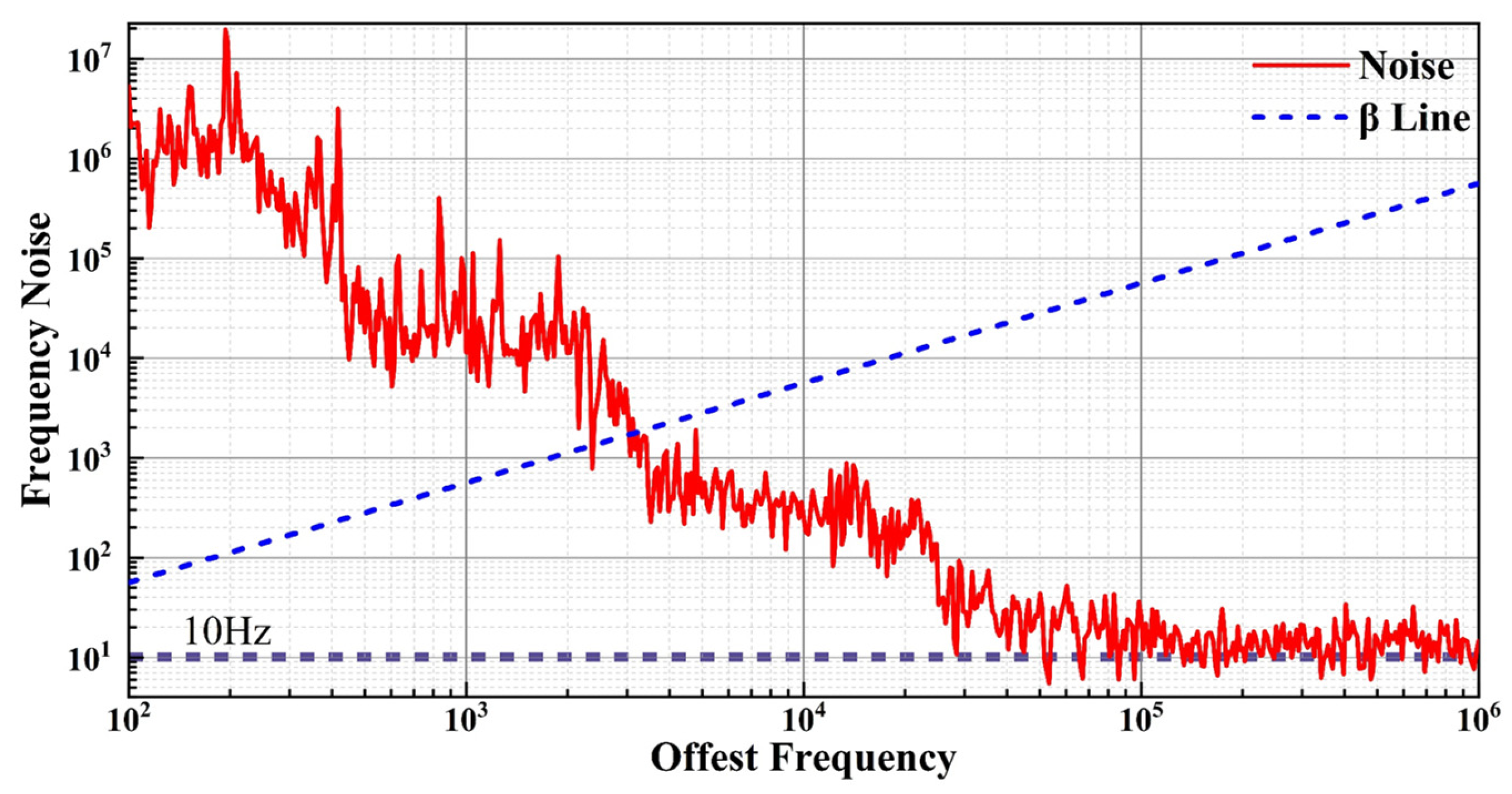
The normalized frequency noise spectrum of the laser is shown in
Figure 9. By plotting the β-separation line, the frequency noise spectrum can be divided into two regions: noise components above the β line are considered the primary contributors to linewidth broadening, while noise components below the β line mainly affect the wings of the laser spectral profile without directly causing an increase in linewidth. Integration of the frequency noise curve over a time interval of 1 ms yields an integrated laser linewidth of approximately 10 kHz. Moreover, the incorporation of a long FBG external cavity and a high-Q micro-ring resonator in the laser system effectively suppresses the laser’s phase and frequency noise, resulting in a significant reduction of its intrinsic linewidth. According to the theoretical calculation, the intrinsic linewidth of the laser is approximately 31 Hz, demonstrating that the self-injection locking mechanism leads to substantial linewidth compression [
27,
28]. It is also noteworthy that a pronounced drop in the noise spectrum occurs in the frequency range of approximately 2 kHz to 3 kHz. This further confirms the significant filtering effect provided by the high-Q micro-ring resonator within the system, effectively suppressing frequency noise in this range and thereby enhancing the spectral purity of the laser.

