Abstract
In this paper, we design a new type of terahertz orbital angular momentum (OAM) optical fiber with excellent transmission characteristics over a wide frequency range. Within the 0.8–1.8 THz frequency band, it shows stable support for transmission of the fifth-order OAM mode. Its dispersion control effect is excellent; it maintains the confinement loss of most modes at the extremely low level of 10−10 dB/m; its maximum dispersion is only 5.57 ps/THz/cm; and its effective mode field area is greater than 1.11 × 10⁻⁷ m2. These characteristics jointly endow this optical fiber with broad application prospects and significant research value in the field of terahertz communication. With the continuous advancement of technology in this field, this optical fiber is expected to become a key component when building efficient, reliable, and large-capacity communication systems.
1. Introduction
With the rapid development of technologies such as the Internet of Things, big data, and artificial intelligence, demand for communication capacity is increasing [1]. As a new communication medium, terahertz photonic crystal OAM fiber has broad prospects for application. For example, it can be used in high-speed Internet, satellite communications, data center interconnection, and other fields to provide higher transmission rates and greater capacity for future communication systems [2]. Research into this fiber is of great significance for promoting the development of terahertz communication technology. The design of an optical fiber capable of high-performance OAM mode transmission can be used to address serious absorption loss and external disturbance resistance in the terahertz band while achieving long-distance transmission and high-capacity communication [3]. In addition, OAM-based MDM technology provides a new method for expanding channel capacity and improving communication quality, which has significant research value.
In optical fibers, OAM modes are formed through the linear combination of the odd and even modes of the vector eigenmodes HE or EH with a phase difference of π/2. This endows OAM modes with unique properties, enabling them to stably transmit in optical fibers and carry orbital angular momentum information [4,5,6]. When the topological charge is greater than 1, a mode group consists of four OAM modes. These modes show different polarization and phase characteristics in optical fibers but are all combined based on the same topological charge. They can coexist and independently transmit information, providing more options for optical fiber communication. When the topological charge is equal to 1, a mode group only consists of two OAM modes. This is because in the special case of 1, the method of combining vector eigenmodes is relatively simple, resulting in a reduction in the number of OAM modes generated.
In recent years, researchers have successfully developed photonic crystal fibers that support orbital angular momentum mode transmission in the terahertz band through precise design and manufacture. In 2017, Haisu L et al. designed a multi-mode Kagome hollow-core fiber capable of supporting second-order OAM mode transmission [7]. They identified two low-loss windows in the range of 0.2 to 0.9 THz, covering a broadband width of 0.25 THz. In 2021, Sharif V et al. proposed a hollow fiber consisting of a circular stomatal array-guiding terahertz OAM mode with a topological charge order of up to 3; it was capable of recognizing two low-loss transmission windows to transmit OAM modes [8]. In 2022, Xue L et al. [9] proposed a high-birefringence, low-loss hollow THz fiber, with birefringence reaching 10−3 in the transmission window of 0.38–0.50 THz. In 2023, Xue et al. [10] designed a THz air-core anti-resonant fiber which also demonstrated high birefringence and low loss, with a birefringence of 10−2 in the range of 0.21–0.35 THz. The maximum value of birefringence was 4.61 × 10⁻² and the loss was 0.15 cm−1 at 0.21 THz. These fibers usually have a special air hole arrangement and optimized structural parameters, allowing them to achieve high performance in OAM mode transmission. The authors analyzed the transmission characteristics of terahertz photonic crystal orbital angular momentum fibers, including key parameters such as mode purity, confinement loss, and dispersion. Low confinement loss, high mode purity, and low crosstalk are important indicators that can be used to evaluate the performance of OAM fibers. Low confinement loss means that the energy loss of the signal is small when it is transmitted in the fiber, which is conducive to maintaining high signal fidelity. High mode purity ensures the purity of the OAM mode and reduces crosstalk and interference between modes. Low crosstalk helps to maintain independence between different OAM modes and improve the overall performance of the communication system [11,12]. For terahertz optical fiber communication systems, it is essential that the operating bandwidth is wide enough [13]. This can not only support greater OAM mode transmission, but also improves the flexibility and adaptability of the communication system. A wide operating bandwidth means that the system can select the appropriate OAM mode for communication over a wider frequency range, thereby optimizing transmission performance and capacity.
In this paper, we design a new type of terahertz OAM fiber which shows excellent performance in many respects, including low loss, support for multi-stage OAM mode transmission, wide frequency range, good dispersion control, and moderate effective mode area. The fiber supports fifth-order OAM mode transmission in the frequency range of 0.8–1.8 THz; its confinement loss for most modes remains in the order of 10−10 dB/m; its maximum dispersion is 5.57 ps/THz/cm; and its effective mode area is in the range of 1.11 × 10⁻⁷ m2 to 3.65 × 10⁻⁷ m2. These characteristics provide broad application prospects and important research value in the field of terahertz communication. In future, with the continuous development of terahertz communication technology, this fiber is expected to become a cornerstone of efficient, reliable, and large-capacity communication systems.
2. Design of the Terahertz OAM PCF
In a terahertz optical fiber communication system, the OAM mode is transmitted stably in the optical fiber, the structure of which must meet some special requirements. In order to avoid the unnecessary dissipation of energy, the transmission region of the fiber must match the shape of the OAM mode field to ensure stable mode transmission in the fiber [14,15]. Stimulating multiple OAM modes can increase the capacity and flexibility of the communication system. However, as they may be coupled with OAM modes, the presence of higher-order radial modes increases the complexity of mode demultiplexing, resulting in signal interference and distortion. Therefore, the design of an optical fiber should avoid the excitation of high-order radial modes, or effectively separate them from OAM modes by specific technical means. In order to guarantee that the transmission of OAM modes in the fiber is maintained, the effective refractive index difference between modes needs to be large enough (usually greater than 10−4) [16,17,18]. This can ensure that each mode maintains its independence and stability during the transmission process and reduce the mutual interference between modes.
Based on the specific case of an OAM mode in an optical fiber, we conducted an in-depth analysis of the relationship between the structural parameters of the optical fiber and other parameters such as mode purity, mode quantity, and confinement loss. According to the above design criteria, we proposed a new structural design scheme for terahertz photonic crystal orbital angular momentum optical fibers, as shown in Figure 1. We defined the radius of the central air hole as t0, the thickness of the annular core as d, the tube wall thickness as t1, and the thickness of each layer of air holes as t2. As shown in Figure 1, the dimensions of all layers are the same.
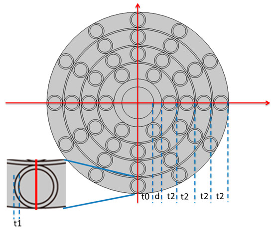
Figure 1.
Schematic diagram of the terahertz OAM PCF.
The main differences between a terahertz fiber and an ordinary fiber are the transmission band and material composition. Ordinary optical fibers are primarily designed to transmit optical signals in the visible or infrared bands, while terahertz fibers are specifically designed to transmit signals in the terahertz band. Terahertz fibers are mostly made of polymer materials, which experience less absorption loss in the terahertz band, and can transmit terahertz waves more efficiently. In this design, the conductive ring is made of cycloolefin copolymer (TOPAS) material with a high refractive index of 1.53 and good transparency, making it ideal for guiding optical signal transmission in the fiber. The substrate is polytetrafluoroethylene (PTEE) with a refractive index of 1.43, which has good mechanical properties and chemical stability, ensuring the long-term stable operation of the fiber.
The main structural advantage of terahertz OAM PCFs compared with ordinary terahertz OAM fibers is the introduction of a photonic crystal microstructure. This microstructure is usually composed of a series of regularly arranged air holes, and the size, shape, and arrangement of these air holes and the refractive index difference between the core and the cladding can be used as adjustable parameters. The flexible adjustment of these parameters gives terahertz OAM PCFs greater freedom to control the propagation characteristics of light, making it possible to achieve better transmission performance.
The spin–orbit coupling effect can be effectively reduced by adjusting the thickness of the high-refractive-index ring region, which is key to improving the anti-interference performance of the OAM mode. The average refractive index of the cladding area was calculated by dividing the cladding area into three regions and calculating the weighted average according to the refractive index and the area occupied by each region. Therefore, the average refractive index of the cladding region can be changed by adjusting the thickness of the tube wall in the cladding to obtain the best transmission performance. Figure 2a shows the relationship between the effective refractive index difference and the tube wall thickness. As can be seen from the figure, with a tube wall thickness t1 in the range of 10–30 μm, the effective refractive index difference between the adjacent HE and EH modes in the same OAM mode group is greater than 10−4. Therefore, when the value is 18 μm, the effective refractive index difference between adjacent modes is relatively large. Due to the larger size of terahertz optical fibers compared to traditional optical fibers in the standard wavelength range, changes in the core thickness will cause significant variations in the performance of the optical fibers. In order to obtain the optimal structural parameters, it is necessary to conduct large-scale simulations while varying the parameters. Within certain small frequency ranges, there may be excessive mode loss. The optimal parameters were found by searching within the intervals where the effective refractive index difference trend was shown to be stable between different modes in the same group.
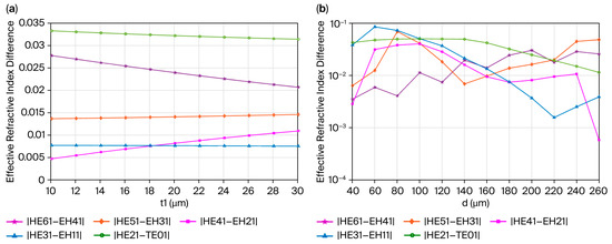
Figure 2.
The effective refractive index difference as a function of (a) the tube wall thickness t1 for different vector modes and (b) the annular core thickness d for the EH and HE modes.
Figure 2b shows the relationship between the effective refractive index difference and the core thickness d. As shown, when the core thickness d ranges from 40 to 260 μm, and the value is 100 μm, the effective refractive index difference between the adjacent HE and EH modes in the same group is relatively large. The main parameters in the simulation are shown in Table 1.

Table 1.
Main parameters in the simulation.
3. Properties of the Designed Terahertz OAM PCF
In this section, we outline the simulation model of the PCF, which was created using the COMSOL Multiphysics software version 6.0. Subsequently, the field quality and transmission characteristics of the OAM mode were analyzed using the full-vector finite element method. In non-weakly guided optical fibers, the composition of the vector OAM modes is as follows:
where m and n are integers representing the radial and angular order, and the superscript “±” corresponds to left-hand and right-hand circular polarization, respectively. It is well known that an OAM mode is formed by the superposition of the π/2 phase difference between odd and even modes. When the number of topological charges is greater than 1, a mode group consists of four OAM modes. Conversely, when m is equal to 1, only two OAM modes make up a group. This is because the propagation constants of the TE0,n mode and the TM0,n mode differ significantly, and thus the OAM modes they form cannot remain stable. Therefore, it is possible to study the properties of OAM modes through the odd–even intrinsic modes HE or EH. An OAM mode takes the form of an electromagnetic wave with a helical phase wavefront, and its electric field intensity is usually distributed in a ring. This characteristic gives OAM modes potential application value in optical communication and optical information processing. The distribution of electric field intensity in Figure 3 shows the characteristics of the OAM modes composed of HE31 and EH11 under the condition of 1.2 THz frequency. As can be seen from the figure, the intensity shows a circular distribution, which is indeed consistent with the characteristics of an OAM mode. This annular distribution indicates that the field strength forms a “doughnut” shape across the cross-section of the fiber, meaning that it is weaker in the central region and stronger at the edges.

Figure 3.
Distribution of electric field intensity in HE31 and EH11 modes.
The phase distribution of an OAM mode is helical, which is its most remarkable feature. Figure 4 shows the phase distribution characteristics of the HE31 and EH11 modes as examples under the 1.2 THz frequency condition. The concentric circles in the phase diagram are called isophase lines, which represent a set of points with equal phase values. The interval between the isophase lines corresponds to the constant difference in the phase in order to distinguish the different modes. It can be clearly seen from the figure that the number of equiphase lines is the topological charge number 2. Topological charge is a key parameter in OAM mode distribution that determines the helical number and direction of the phase wavefront. With a topological charge of 2, the phase wavefront will complete two helices, which usually means that the beam will experience two complete phase change cycles during its propagation.
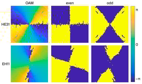
Figure 4.
Phases of electric field intensity in HE31 and EH11 modes.
Polarization describes changes in the direction and magnitude of a beam’s electric field vector with time. In an OAM mode, the polarization distribution shows complex and diverse forms which are closely related to its phase structure, quantum number, and production mode. Figure 5 shows the polarization distribution of the eigenmodes when the topological charge is 2. In the figure, small colored ellipses are used to represent the polarization states of the electric field vector, where the direction and magnitude of each ellipse reflect the direction and magnitude of the electric field vector, respectively. Due to the complexity of OAM modes, the distribution of these ovals across cross-sections is often uneven, resulting in unique polarization patterns. In the figure, the ellipticity of each small colored ellipse is used to represent spin–orbit coupling strength. Spin–orbit coupling is a physical phenomenon that describes the interaction between spin angular momentum (SAM) and OAM in a light beam. The larger the ellipticity, the more complex the direction and size distribution of the electric field vector in the cross-section, and the greater the spin–orbit coupling strength.
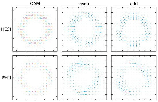
Figure 5.
Polarization distribution of electric field intensity in HE31 and EH11 modes.
Figure 6a shows that the effective refractive index of different vector modes increases with an increase in frequency. This is an important parameter used to describe the mode propagation in an optical fiber, which reflects the phase velocity of the light wave propagating in the waveguide. In Figure 6, the value of the effective refractive index varies between 1.05 and 1.48, indicating that the propagation of light waves through the waveguide slows down and the phase delay increases as the frequency increases. The figure also shows that the effective refractive indices of the four modes in the same module group are relatively close. This means that the propagation properties of these modes in waveguides are similar, and the interaction between them may be weaker, helping to maintain signal stability and clarity in optical communications and other applications. Figure 6b shows the difference in effective refractive index between the EH and HE modes with frequency. This is an important factor for measuring differences in propagation speed between different modes. For higher-order modes, Figure 6b shows that the effective refractive index difference in adjacent modes first increases and then decreases as frequency increases. This means that in the high-frequency range, the difference in propagation speed between high-order modes may first increase and then decrease, which may be related to the dispersion effect in the waveguide. Unlike the high-order mode, the effective refractive index difference in the low-order mode decreases as frequency increases. This shows that in the low-frequency range, the difference in propagation speed between low-order modes gradually decreases, which helps to maintain signal stability and consistency in optical communication.
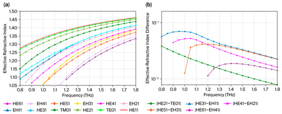
Figure 6.
(a) The effective refractive index as a function of the frequency for different vector modes. (b) The effective refractive index difference as a function of the frequency for EH and HE modes.
In PCFs, due to the limitations of lateral distribution, confinement loss occurs, which is mainly determined by the imaginary part of the effective refractive index. Figure 7 presents the maximum confinement loss in various terahertz OAM PCF modes in the frequency range of 0.8 THz to 1.8 THz. Except for the EH41 and HE61 modes, the maximum constraint loss is approximately 10−10 dB/m. The mode field distribution of high-order modes is more complex and easily coupled with the periodic structure in the PCF cladding, resulting in energy leaking into the radiation mode. The low confinement loss indicates that the designed PCF structure is effective at constraining OAM modes, which can effectively suppress mode field diffusion and avoid phase distortion.
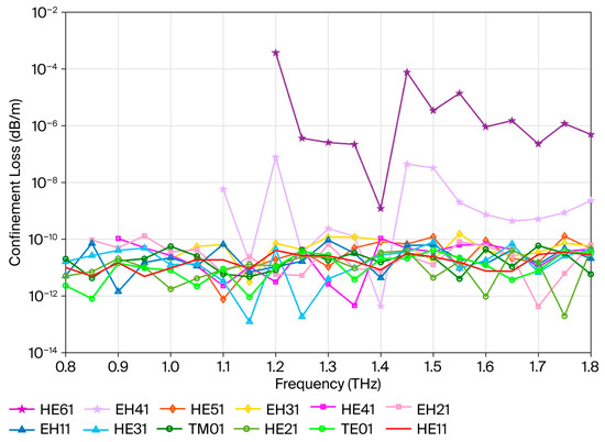
Figure 7.
Confinement loss as a function of frequency for different modes.
Dispersion is a separation phenomenon caused by different frequencies of light traveling at different speeds in the medium. As shown in Figure 8, the mode dispersion gradually decreases as the frequency increases. This means that at higher frequencies, the difference in the propagation speed of different light wavelengths is reduced in the medium, so the dispersion phenomenon is weakened. The figure also shows the dispersion difference between the higher-order and lower-order modes. The dispersion of the higher-order modes changes more significantly than that of the lower-order modes. This is because higher-order modes have more complex propagation paths through the medium, or they are more sensitive to changes in its properties. As a result, the dispersion of higher-order modes exhibits greater fluctuations as the frequency changes.
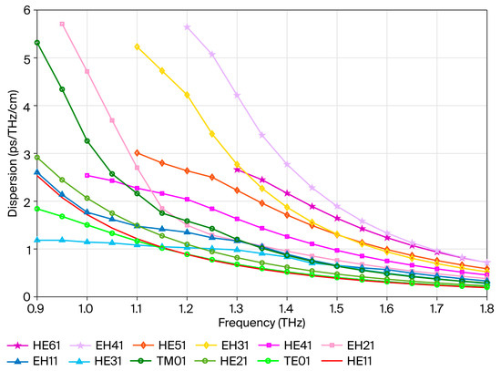
Figure 8.
Dispersion as a function of frequency for different modes.
Figure 9 shows that as the frequency increases, the effective mode field area of the fiber decreases. This is an important optical property that reflects the distribution of energy as light waves travel through the fiber. A decrease in the effective mode field area will cause the signal attenuation in the fiber to increase. This is because energy leakage can lead to a reduction in the intensity of the optical signal, which affects its transmission quality and distance.
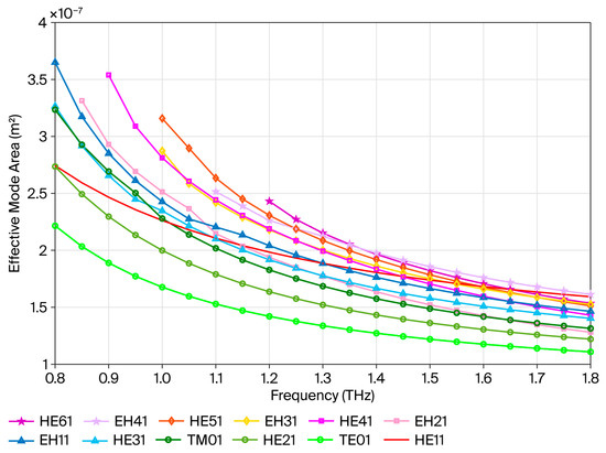
Figure 9.
Effective mode area as a function of frequency for different modes.
Figure 10 shows that the numerical aperture curves of various OAM modes are very close, in the frequency range of 0.8 THz to 1.8 THz. This indicates that at the aforementioned frequency conditions, the ability of the fiber to bind to different OAM modes is similar, or that the propagation characteristics of these modes in the fiber are relatively stable. Although the curves of each mode are close, the numerical aperture increases with frequency. This is because the high-frequency light alters the effective refractive index difference between the core and the cladding of the optical fiber, or the propagation mode characteristics of the light, thereby counteracting the originally weakened binding effect of short-wavelength light, and ultimately increasing the numerical aperture. This means that at higher frequency, the optical fiber may receive a smaller range of light angles, affecting its coupling efficiency and transmission performance.
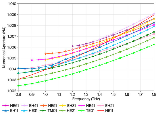
Figure 10.
Numerical aperture as a function of frequency for different modes.
Figure 11 shows that in the frequency range of 0.8 to 1.8 THz, the purity of all vector modes in the terahertz OAM PCF increases with the transmission frequency, ranging from 80% to 96%. This shows that as the frequency increases, the vector mode in the fiber becomes more stable, with less coupling or interference with other modes, thus maintaining a high mode purity.
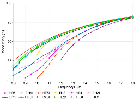
Figure 11.
Mode purity as a function of frequency for different modes.
4. Conclusions
In this study, we focus on the transmission characteristics of terahertz waves in photonic crystal fibers. Through theoretical modeling and numerical simulations, we systematically explored the influence of structural parameter optimization, material selection, and nonlinear effect control on the performance of a THz PCF. We propose an air hole structure based on a circular core, which optimizes the thickness of the fiber core and tube wall to achieve confinement losses up to 10−3 orders of magnitude lower in the 0.8–1.8 THz frequency band. It has excellent transmission characteristics, with a low confinement loss below 10−3 dB/m, a dispersion of 5.57 ps/THz/cm, an effective mode area above 3.65 × 10⁻⁷ m2, and a mode purity above 81%. The fiber explored in this study addresses the key technological bottlenecks of THz PCFs due to its low loss, high nonlinearity, and multifunctional integration through combined structural and material innovation, providing high-performance solutions for photonic devices in fields such as 6G communication, biosensing, and terahertz imaging.
Author Contributions
Methodology, J.Y.; software, W.L.; validation, J.Y.; formal analysis, J.Y.; investigation, J.Y.; writing—original draft preparation, J.Y. All authors have read and agreed to the published version of the manuscript.
Funding
This work is partly supported by the Science and Technology Project of Hebei Education Department (BJK2023110) and the Natural Science Foundation of Hebei Province (F2021408002).
Data Availability Statement
The original contributions presented in this study are included in the article. Further inquiries can be directed to the corresponding author.
Conflicts of Interest
The authors declare no conflict of interest.
Correction Statement
This article has been republished with a minor correction to the Data Availability Statement. This change does not affect the scientific content of the article.
References
- Chang, H.; Meng, Y. Terahertz polymer vortex photonic crystal fiber with low confinement loss and flat dispersion for stable transmission of 92 orbital angular momentum modes. Opt. Quantum Electron. 2024, 56, 267. [Google Scholar] [CrossRef]
- Chen, X.; Yan, D.; Qiu, J.; Zhu, Z.; Li, X.; Zhang, L.; Sun, S.; Li, J. Design and investigation of a terahertz hollow-core fiber with double-layer ring core for OAM mode transmission. Phys. Scr. Int. J. Exp. Theor. Phys. 2024, 99, 105511. [Google Scholar] [CrossRef]
- Pan, Z.; Zhou, Z.; Song, Z. Terahertz generations of transmissive deflection, focusing, and orbital angular momentum with polarization conversion. Opt. Laser Technol. 2023, 159, 109036. [Google Scholar] [CrossRef]
- Zhang, H.; Zeng, I.; Lu, X.; Wang, Z.; Zhao, C.; Cai, Y. Review on fractional vortex beam. Nanophotonics 2022, 11, 241–273. [Google Scholar] [CrossRef] [PubMed]
- Zhang, H.; Zhu, J.; Lu, X.; Hu, Z.; Gao, J.; Liu, K.; Zhan, Q.; Cai, Y.; Zhao, C. Single-shot phase retrieval for randomly fluctuated and obstructed vortex beams. Sci. China Phys. Mech. Astron. 2024, 67, 72–80. [Google Scholar] [CrossRef]
- Zhang, H.; Hu, Z.; Wang, Z.; Zhu, J.; Lu, X.; Qiu, S.; Peng, P.; Zhan, Q.; Cai, Y.; Zhao, C. Inverse vortex beams: Reverse control of radius. Opt. Laser Technol. 2025, 184, 112478. [Google Scholar] [CrossRef]
- Li, H.; Ren, G.; Zhu, B.; Gao, Y.; Yin, B.; Wang, J.; Jian, S. Guiding terahertz orbital angular momentum beams in multimode Kagome hollow-core fibers. Opt. Lett. 2017, 42, 179–182. [Google Scholar] [CrossRef]
- Sharif, V.; Pakarzadeh, H. Terahertz hollow-core optical fibers for efficient transmission of orbital angular momentum modes. J. Light. Technol. 2021, 39, 4462–4468. [Google Scholar] [CrossRef]
- Xue, L.; Sheng, X.; Lou, S.; Zhao, G.; Yang, S.; Xing, Z.; Jia, H. High-birefringence low-loss hollow-core THz waveguide embedded parallel slab cladding. IEEE Trans. Terahertz Sci. Technol. 2022, 12, 471–480. [Google Scholar] [CrossRef]
- Xue, L.; Sheng, X.; Mu, Q.; Kong, D.; Wang, Z.; Chu, P.K.; Lou, S. 3D-printed high-birefringence THz hollow-coreanti-resonant fiber with an elliptical core. Opt. Express 2023, 31, 26178–26193. [Google Scholar] [CrossRef]
- Liang, Y.; Wang, H.; Zhang, X.; Ai, J.; Ma, Z.; Ramachandran, S.; Wang, J. Reconfigurable structured light generation and its coupling to air–core fiber. Adv. Photonics Nexus 2023, 2, 036015. [Google Scholar] [CrossRef]
- Liang, Y.; Hu, X.; Wang, Q.; Wang, J. Tailoring optical vortex beams based on diffractive neural networks for high-quality ring-core fiber coupling. Opt. Lett. 2025, 50, 3788–3791. [Google Scholar] [CrossRef] [PubMed]
- Zheng, W.; Qin, Y.; Xu, O.; Xiang, M.; Peng, D.; Fu, S.; Li, J. Wideband low confinement loss anti-resonant hollow core fiber with nested U-shape tube. Opt. Express 2021, 29, 24182–24192. [Google Scholar] [CrossRef] [PubMed]
- Yu, Y.; Zhang, X.; Zhang, Q.; Wang, K.; Yang, Y.; Wang, Z.; Wang, Y.; Huang, Y.; Wen, J.; Chen, W.; et al. Parametric optimization for low loss negative curvature hollow core fiber with elliptical tube. J. Light. Technol. 2023, 41, 293–300. [Google Scholar] [CrossRef]
- Jaworski, P.; Yu, F.; Carter, R.M.; Knight, J.C.; Shephard, J.D.; Hand, D.P. Light transmission in negative curvature hollow core fiber in extremely high material loss region. Opt. Express 2015, 23, 8498–8506. [Google Scholar] [CrossRef]
- Wang, Y.Y.; Wheeler, N.V.; Couny, F.; Roberts, P.J.; Benabid, F. Low loss broadband transmission in hypocycloid-core Kagome hollow-core photonic crystal fiber. Opt. Lett. 2011, 36, 669–671. [Google Scholar] [CrossRef]
- Hong, Y.; Jia, A.; Gao, S.; Sheng, Y.; Lu, X.; Liang, Z.; Zhang, Z.; Ding, W.; Wang, Y. Birefringent, low loss, and broadband semi-tube anti-resonant hollow-core fiber. Opt. Lett. 2023, 48, 163–166. [Google Scholar] [CrossRef]
- Gong, A.; Qiu, Y.; Chen, X.; Zhao, Z.; Xia, L.; Shao, Y. Biomedical applications of terahertz technology. Appl. Spectrosc. Rev. 2019, 55, 418–438. [Google Scholar] [CrossRef]
Disclaimer/Publisher’s Note: The statements, opinions and data contained in all publications are solely those of the individual author(s) and contributor(s) and not of MDPI and/or the editor(s). MDPI and/or the editor(s) disclaim responsibility for any injury to people or property resulting from any ideas, methods, instructions or products referred to in the content. |
© 2025 by the authors. Licensee MDPI, Basel, Switzerland. This article is an open access article distributed under the terms and conditions of the Creative Commons Attribution (CC BY) license (https://creativecommons.org/licenses/by/4.0/).