Communication

High-Efficiency Deployable V-Band Reflectarray Antenna Design, Tolerance Analysis and Measurement

by
Guang Liu
1,*,
Xiaolong Dong
1,
Di Zhu
1 and
Hongjian Wang
1,2
1
Key Laboratory of Microwave Remote Sensing, National Space Science Center, Chinese Academy of Sciences, Beijing 100190, China
2
University of Chinese Academy of Sciences, Beijing 100190, China
*
Author to whom correspondence should be addressed.
Photonics 2025, 12(9), 866; https://doi.org/10.3390/photonics12090866
Submission received: 5 June 2025 / Revised: 18 July 2025 / Accepted: 22 July 2025 / Published: 28 August 2025

Abstract

A deployable reflectarray antenna (RA) using a three-times expansion structure working at the V-band for 12U CubeSat is presented in this paper. Double-circle ring unit cells with excellent dispersion characteristics are used to constitute the layout of the RA. The impact of the tolerance of the gap between boards on the RA’s radiation patterns are shown and discussed. A high expansion compression ratio of 26:1 is achieved by using the three-times expansion structure design. The measured results of the prototype show that the deployable RA achieves performance with high efficiency, a low side lobe level, a low cross-polarization level and a wide band.

1. Introduction

Deployable reflectarray antennas have been widely used on the CubeSat platform for various applications because of their high expansion compression ratio and low loss. For example, an RHCP deployable RA working at the C-band (8.425 GHz) for deep space communication is shown in [1], and the measured gain and aperture efficiency are 29.2 dB and 41.6%, respectively. A one-meter deployable RA working at the Ka-band (35.75 GHz) for a space-based earth science radar is shown in [2], and the measured gain and aperture efficiency are 48.1 dB and 44%, respectively. An integrated solar array and RHCP deployable RA working at the Ka-band (26 GHz) for radar application are shown in [3], and the measured gain is 33.5 dB. A dual-polarized deployable RA operating at the Ku-band (17.2 GHz) for a synthetic aperture radar (SAR) mission is shown in [4], and the measured gain and aperture efficiency are 36.6 dB and 29.2%, respectively.
A deployable RA working at the V-band for atmospheric pressure sensing [5] on the 12 U Cubesat platform is presented herein. This paper is organized as follows: Section 2 presents the design of the deployable reflectarray antenna and the double-circle ring unit cell. Section 3 presents the tolerance analysis of the impact of the gap between boards on the RA’s radiation patterns. Section 4 presents the RA’s deployment structure design and measurement results. The main conclusions are drawn in Section 5.

2. Deployable Reflectarray Antenna and Unit Cell Design

2.1. Reflectarray Antenna Design

The geometric design of the deployable reflectarray antenna is shown in Figure 1 and the aperture dimension of the RA is D = 91.56λ0 = 504 mm, and its focal length is F = 520 mm, with an F/D ratio of 1.03. The feed is 150 mm offset of the center of the RA with an incident angle of 16.1°, and the outgoing beam pointing angle is also 16.1°. The RA contains 180 × 180 unit cells, and the phase correction function in [6] is used to calculate the reflection phase distribution of the RA for the out beam direction ( θ 0 , φ 0 ), as shown as follows:
φ i x i , y i = k 0 d i sin θ 0 x i cos φ 0 + y i sin φ 0
where k 0 is the propagation constant, and d i is the distance from the phase center of feed to the i t h element:
d i = x i x f 2 + y i y f 2 + z f 2
where (xi, yi) is the element position of the i t h element in the reflectarray, and (xf, yf, zf) is the feed location in Equation (2).
The calculated reflection phase distribution, design process and radiation pattern results of the RA are shown in [7], which indicates that a very high gain of 48 dB is reached by the RA because of its comparatively large aperture dimensions and high aperture efficiency. A very narrow half power beam width (HPBW) of 0.7° and low side lobe level (SLL) of −25 dB are also achieved.

2.2. Unit Cell Design

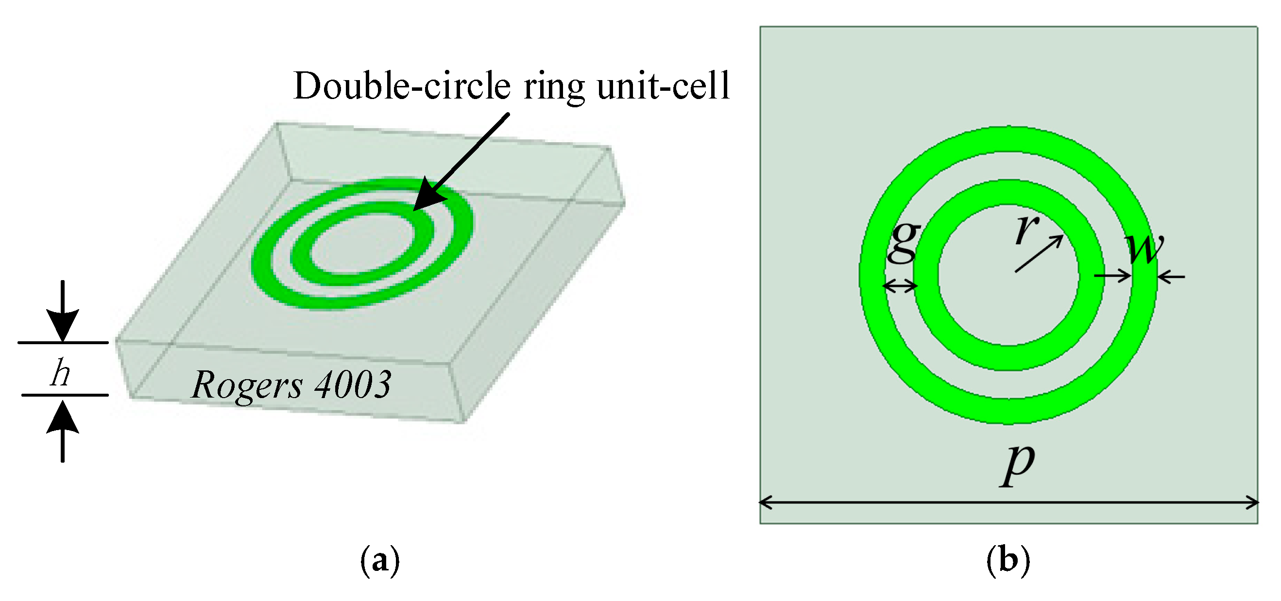
The double-circle ring unit cell is constituted by two concentric circular rings on a Rogers 4003 substrate, as shown in Figure 2a. Rogers 4003 [8] is a material whose thermal coefficient of expansion is similar to that of copper and that could be used in space application and has been used in the MarCO and SWOT missions [9]. The thickness of the RO4003 substrate is h = 0.508 mm. The periodic size of the unit cell is p = 0.51λ0 = 2.8 mm, where λ0 is the wavelength in free space at the center frequency of 54.5 GHz. The width of each ring patch is w = 0.14 mm, and the distance between two rings is g = 0.16 mm, as shown in Figure 2b.
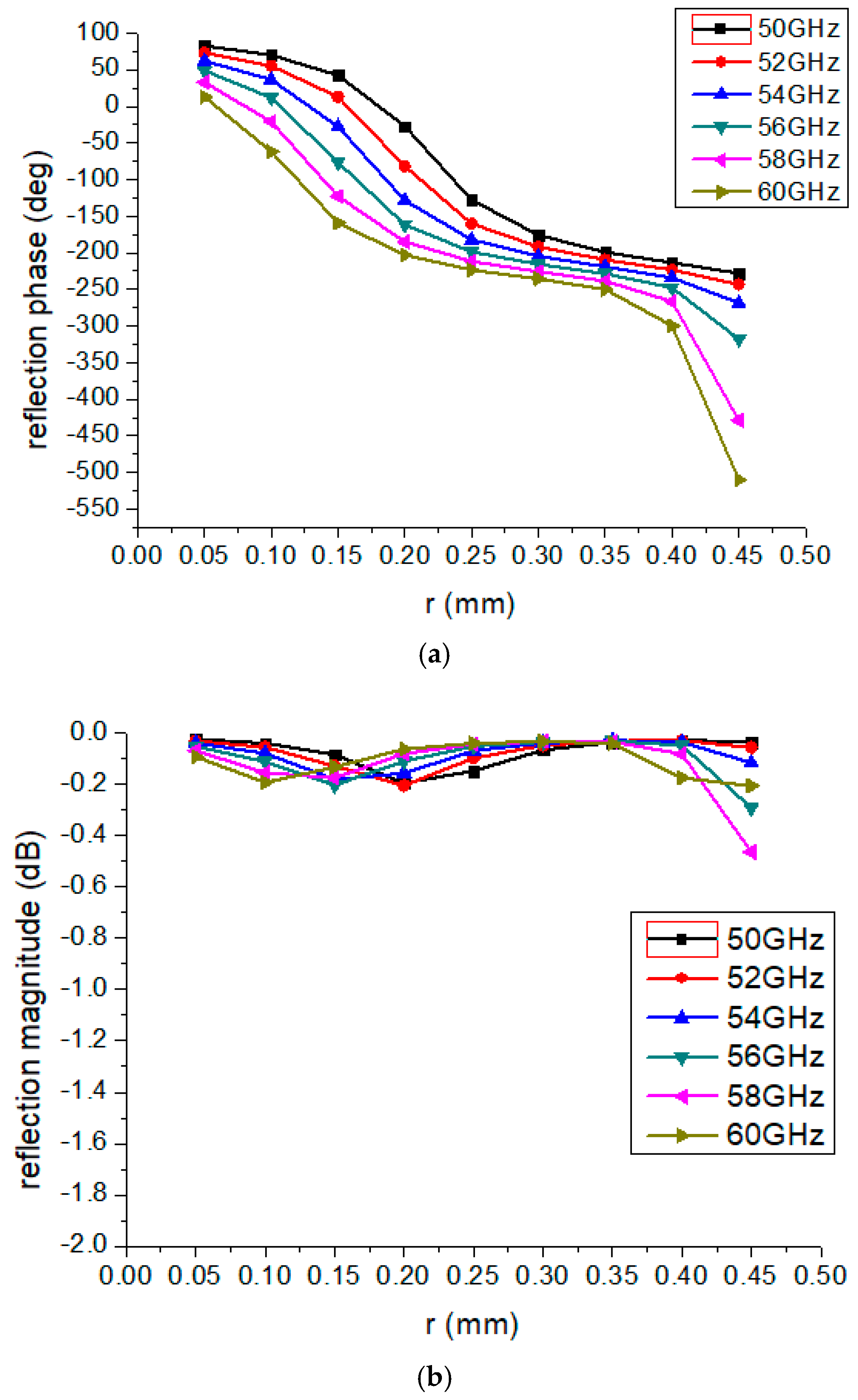
As the radius parameter r varies from 0.05 mm to 0.45 mm, Figure 3 illustrates the reflection phase and magnitude responses of the double-circle ring unit cell across various frequencies from 50 GHz to 60 GHz. The phase curves at different frequencies are nearly parallel to one another, indicating that excellent dispersion characteristics are achieved by the unit cell at the V-band. Within the operating frequency band, the reflection loss of the unit cell remains below 0.5 dB, which indicates low loss performance at the V-band.

3. Deployable Reflectarray Antenna Tolerance Analysis

A pyramidal horn with an illumination edge taper of −10 dB is used as the feed of the RA. The array theory in [10] is used to compute the E-plane and H-plane radiation patterns of the RA. Because the working principle of the RA consists of the unit cell’s ability to compensate for the wave from the feed, and the deployable RA is constituted by three panels, the gap width between the panels is the major parameter that affects the performance of the RA.
The influences of the gap width tolerance of adjacent boards on radiation patterns are analyzed. The gap width increases from 0 mm to 0.5 mm with a step size of 0.1 mm. The computed E-plane and H-plane radiation patterns of the RA at 54.5 GHz with gap widths increasing from 0 mm to 0.5 mm are shown in Figure 4. The computed results indicate that increasing the gap width to 0.5 mm has little impact on the E-plane pattern. The side lobe level of the H-plane pattern increases by about 1.3 dB, but the gain decreases only a little, less than 0.05 dB. The reflection phase compensation that is missing at the gap position is considered the main reason for the side lobe level increases.
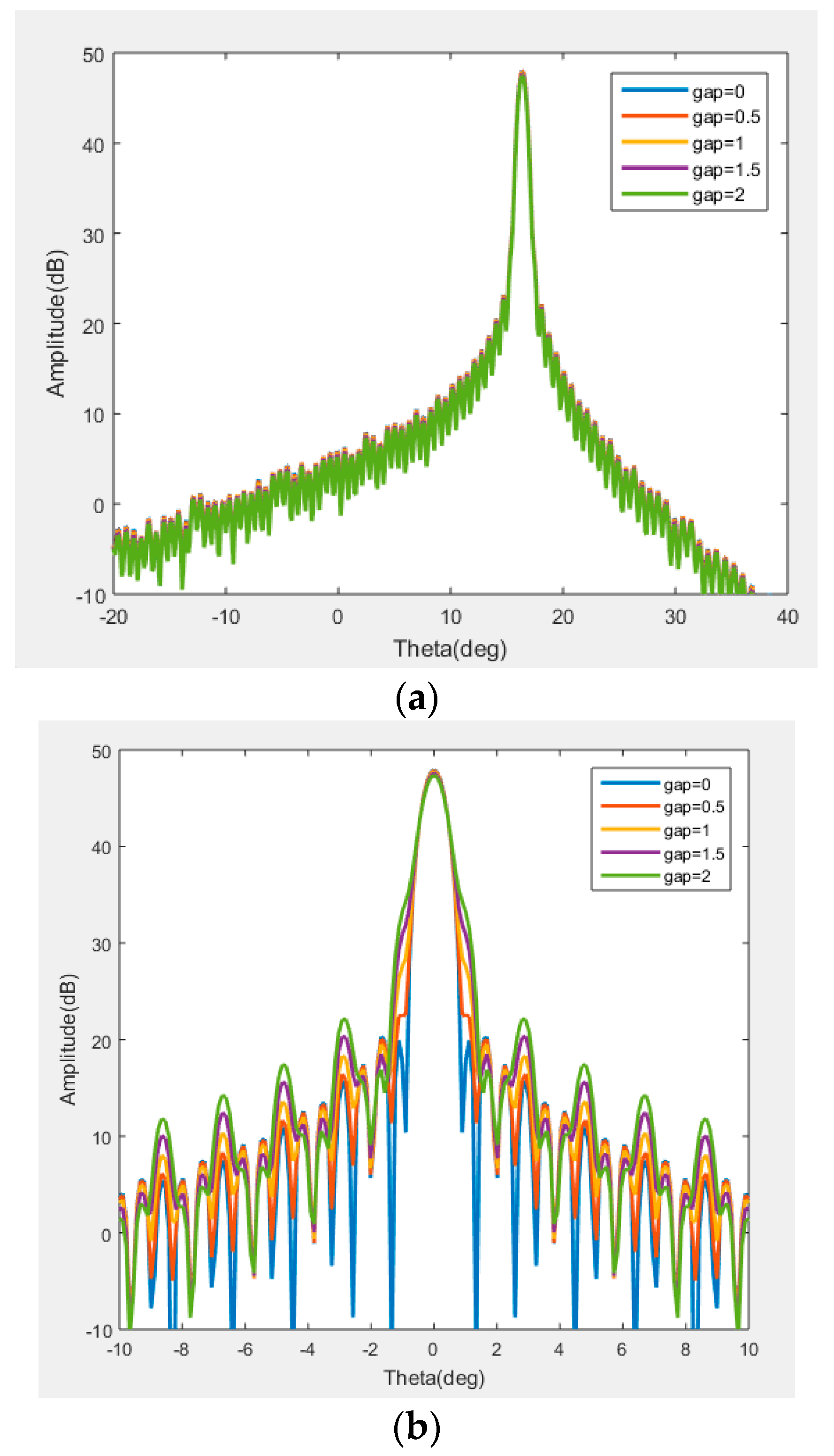
Figure 5 shows the E- and H-plane radiation patterns of the RA as the gap widths increase from 0 mm to 2 mm. The computed results show that the gains of the RA decrease by 0.5 dB, the SLLs of E-plane patterns increase by 0.4 dB and the SLLs of H-plane patterns increase by 2.1 dB. Thus the gap widths between the RA’s boards are better controlled to less than 0.5 mm at the V-band.

4. Reflectarray Antenna Deployment Structure Design and Measurement

4.1. Deployment Structure Design of RA

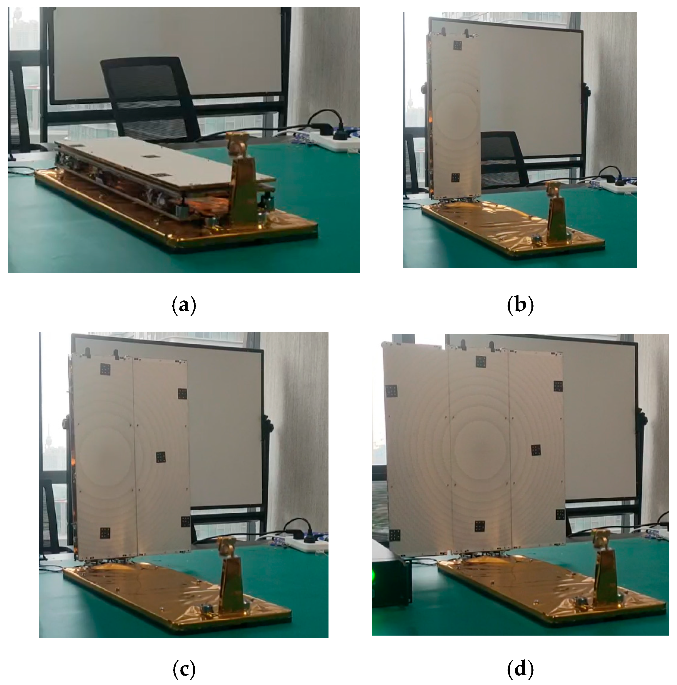
A similar triple deployment mechanism with a deployable RA on Mars Cube One (MarCO) CubeSat [1] is used for reference, and the pictures of the deployable RA prototype are shown in Figure 6. As shown in Figure 6a, three divided RA panels are folded together and pressed on the antenna base, and the folded dimensions of the RA are 504 × 168 × 60 mm3. As shown in the first deployment of the RA in Figure 6b, three folded boards stand up together from the base. In the second deployment, as shown in Figure 6c, the left hinge releases, and then the left board turns left. In the last deployment, as shown in Figure 6d, the right hinge releases, and then the right board turns right. The deployed volume of the RA is 504 × 504 × 520 mm3 , and a comparatively high expansion compression ratio of 26:1 is achieved by the deployable RA prototype. The measured root mean square (RMS) of the deployed prototype’s panel is 0.019 mm.

4.2. Measured Results of Deployable RA

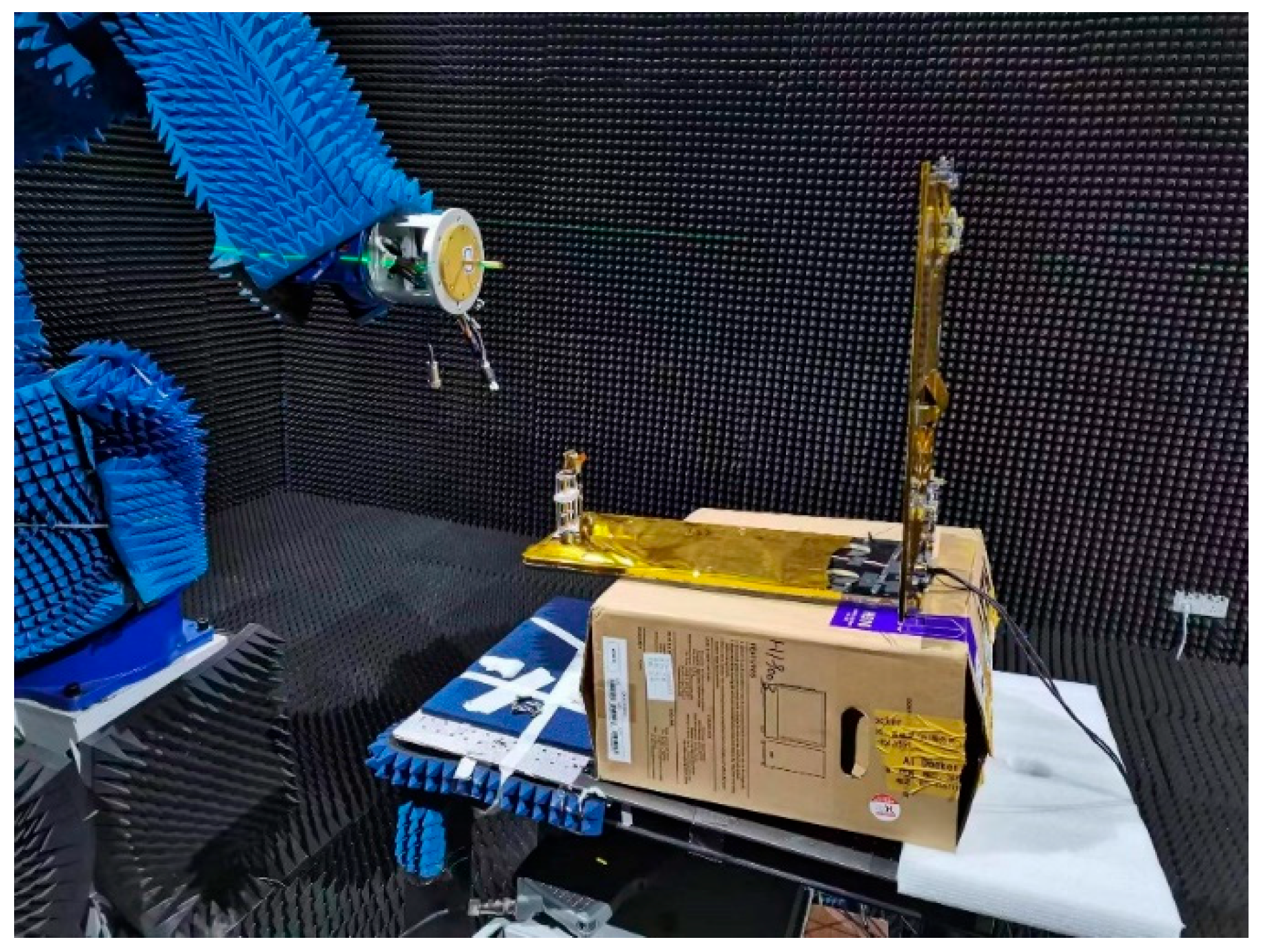
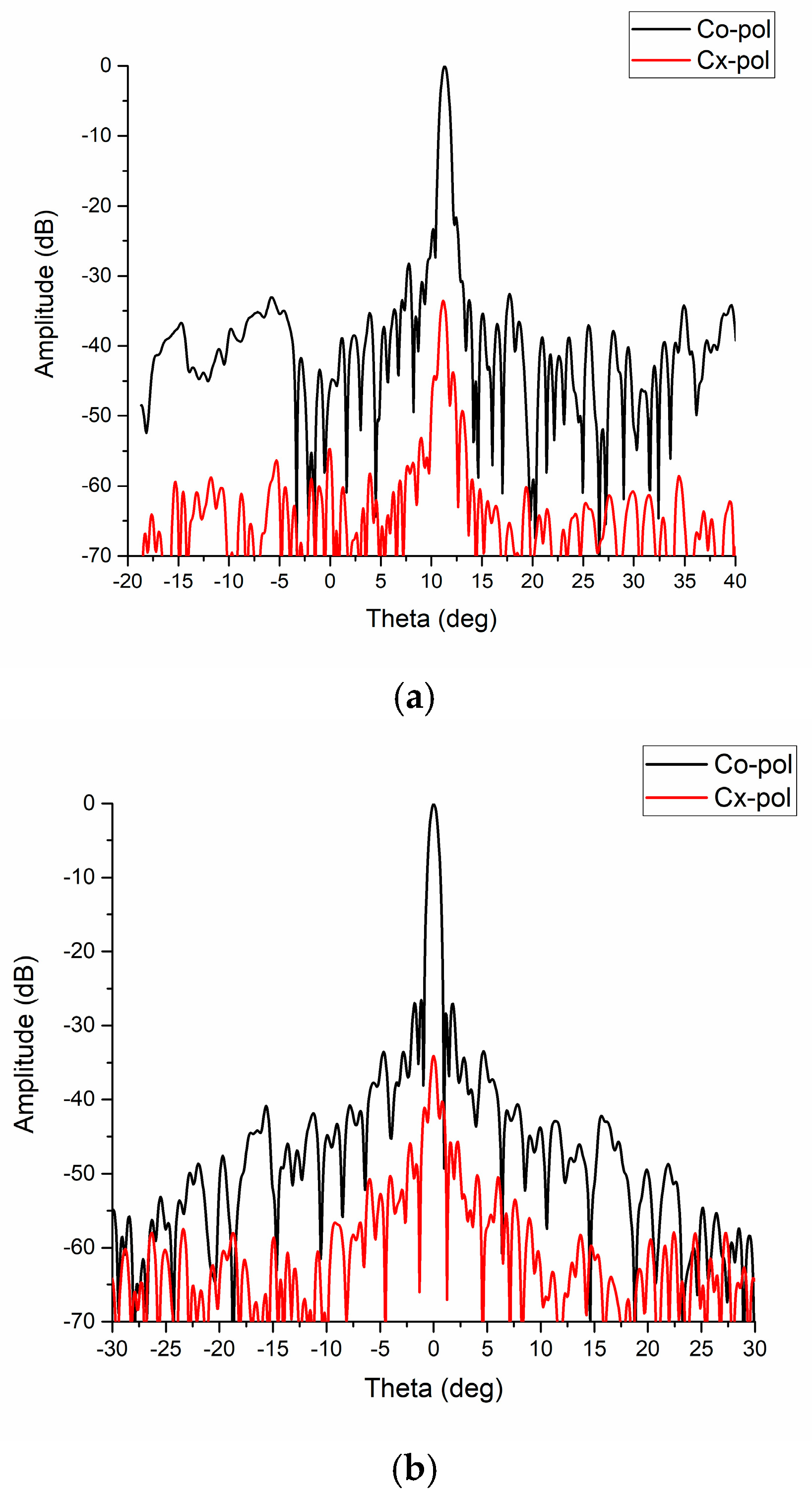
The deployable RA prototype was measured by a Near-field system, as shown in Figure 7. The measured E-plane and H-plane radiation patterns of the RA prototype at 54.5 GHz are shown in Figure 8. A measured high gain of 46.9 dB is reached by the RA, indicating that a relatively high radiation efficiency of 77.6% and aperture efficiency of 46.5% are achieved by the deployable RA. The measured half power beam width (HPBW) is 0.7°, coinciding with the theoretical result very well. The measured E- and H-plane side lobe levels are −21.6 dB and −26 dB, respectively. The measured cross-polarization levels are lower than −34 dB both at the E- and H-planes, which indicates that the RA achieves performance with a low side lobe level and low cross-polarization level.
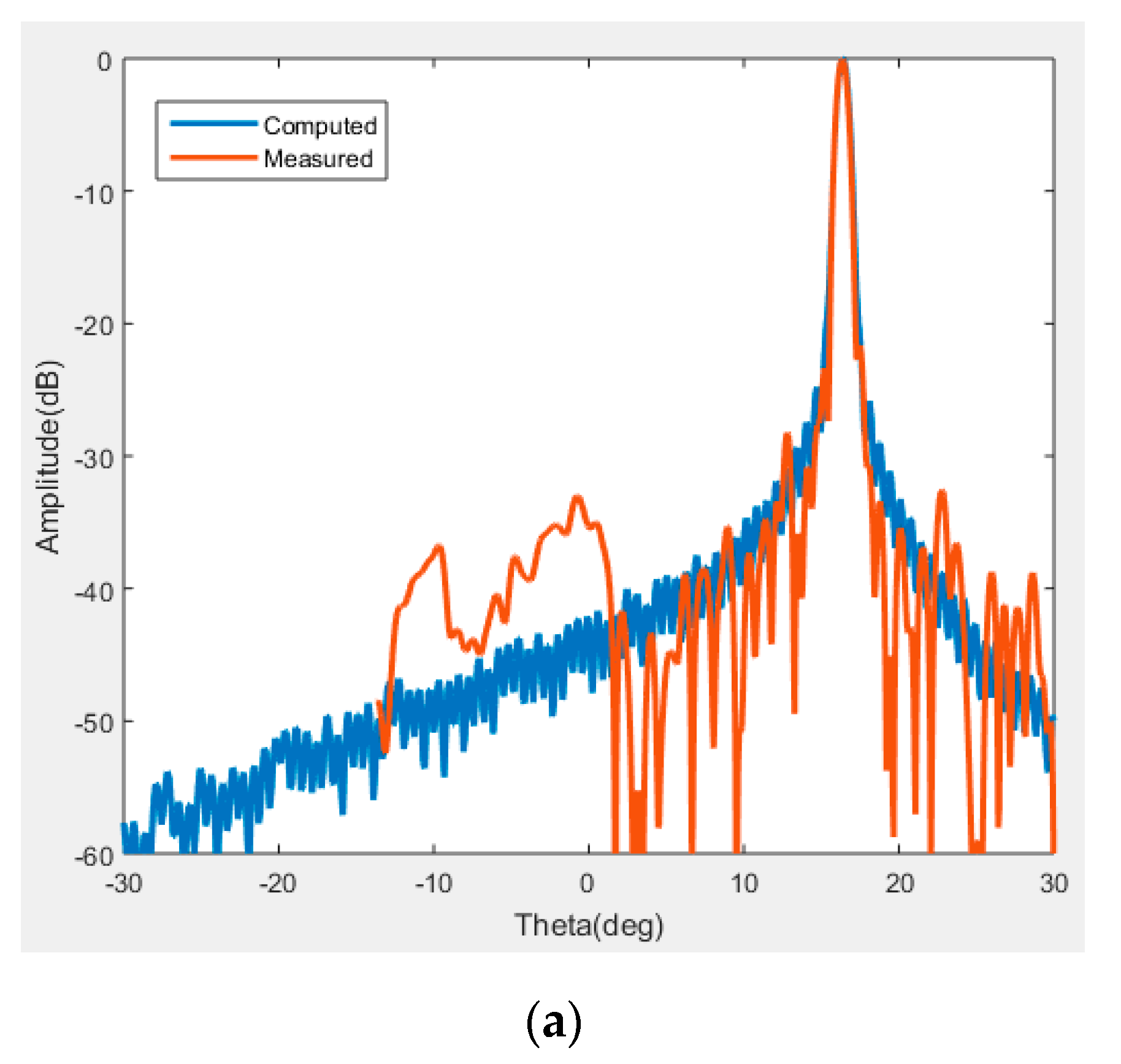
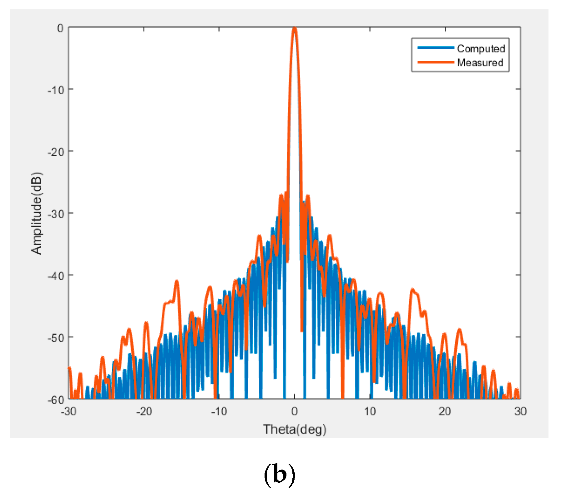
A comparison between the measured and simulated E- and H-plane radiation patterns is shown in Figure 9. The measured radiation patterns are in very good agreement with the simulated results. The lifting left far side lobes of the measured E-plane pattern are because of the blockage of the feed and bracket.
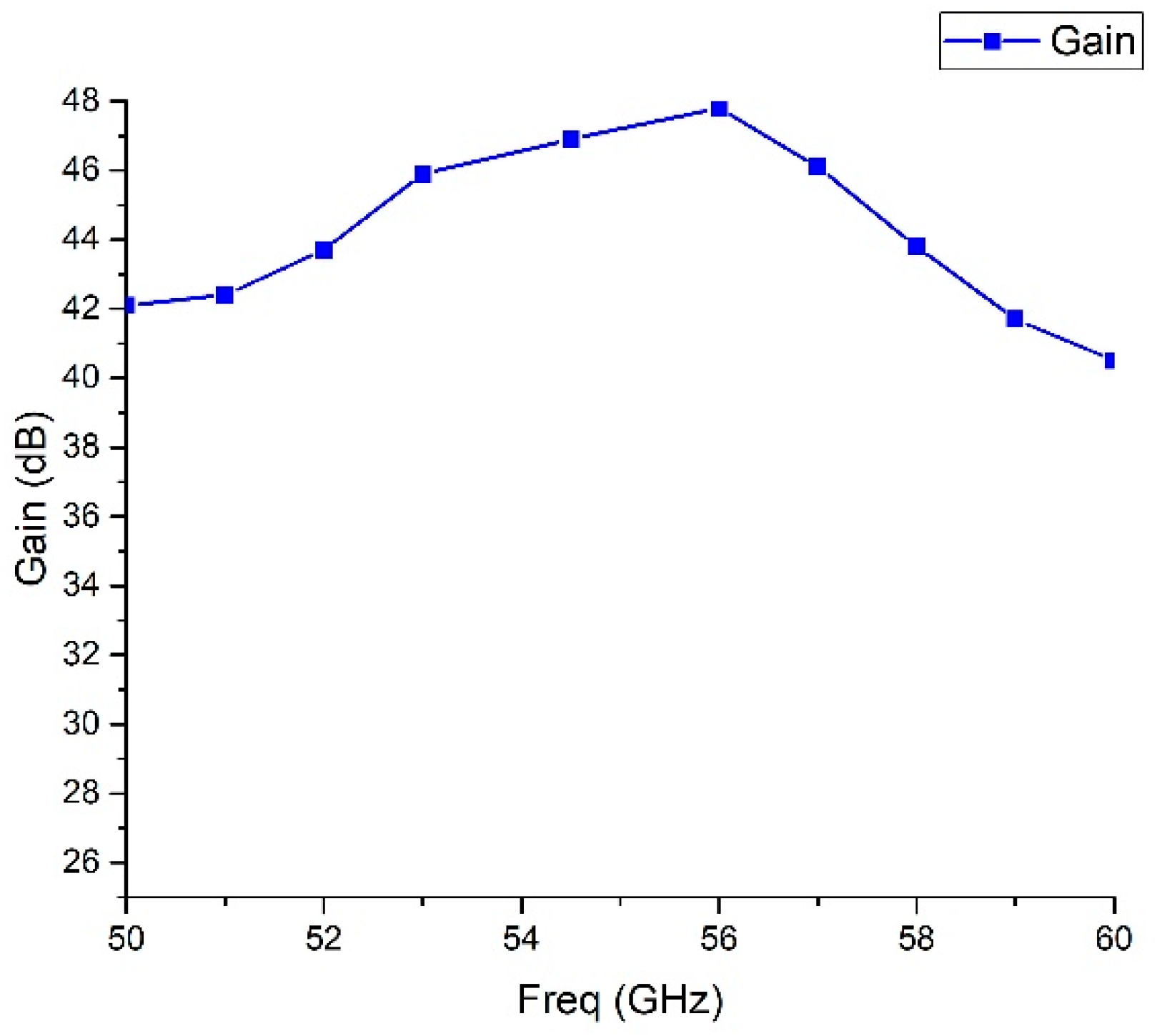
The measured gain of the RA versus frequency is presented in Figure 10. The 3 dB gain bandwidth is 11%, indicating that the RA has wide-band performance.
Table 1 lists the performance parameters of the proposed deployable RA and some recent published works. It can be concluded that the deployable RA has the advantages of high gain, high aperture efficiency and low side lobe level compared to the published designs in [1,2,4].

5. Conclusions

A deployable reflectarray antenna working at the V-band for the CubeSat platform was designed, manufactured and tested. Double-circle ring unit cells with low reflection loss and excellent dispersion characteristics at the working frequency band are used to constitute the RA. The E- and H-plane radiation patterns and radiation performance of the RA do not change very much as the gap width between adjacent boards increases from 0 mm to 0.5 mm. With the triple deployment structural design, an expansion compression ratio of 26:1 of the RA is reached. The measured results of the prototype show that high gain (46.9 dB), high aperture efficiency (46.5%), a low side lobe level (<−21.6 dB), a low cross-polarization level (<−34 dB) and wide-band performance are achieved by the deployable RA.

Author Contributions

Conceptualization, G.L.; Validation, G.L.; Formal analysis, G.L.; Writing—original draft, G.L.; Supervision, D.Z. and H.W.; Project administration, X.D. All authors have read and agreed to the published version of the manuscript.

Funding

No funding support.

Institutional Review Board Statement

Not applicable.

Informed Consent Statement

Not applicable.

Data Availability Statement

Data are contained within the article.

Conflicts of Interest

The authors declare no conflict of interest.

References

  1. Hodges, R.E.; Chahat, N.; Hoppe, D.J.; Vacchione, J.D. A Deployable High-Gain Antenna Bound for Mars: Developing a new folded-panel reflectarray for the first CubeSat mission to Mars. IEEE Antennas Propag. Mag. 2017, 59, 39–49. [Google Scholar] [CrossRef]
  2. Chahat, N.; Agnes, G.; Sauder, J.; Cwik, T. One meter deployable reflectarray antenna for earth science radars. In Proceedings of the 2017 IEEE International Symposium on Antennas and Propagation & USNC/URSI National Radio Science Meeting, San Diego, CA, USA, 9–14 July 2017; pp. 245–246. [Google Scholar]
  3. Hodges, R.E.; Radway, M.J.; Toorian, A.; Hoppe, D.J.; Shah, B.; Kalman, A.E. Isara-integrated solar array and reflectarray cubesat deployable ka-band antenna. In Proceedings of the 2015 IEEE International Symposium on Antennas and Propagation USNC/URSI National Radio Science Meeting, Vancouver, BC, Canada, 19–24 July 2015; pp. 2141–2142. [Google Scholar]
  4. Pelletier, É.C.; Mireault-Lecourt, C.; Laurin, J.-J. Reflectarray Antenna Concept for a Snow Mass Measurement SAR Mission in Ku-Band on a Nanosatellite Platform. IEEE Antennas Wireless Propag. Lett. 2021, 20, 2085–2089. [Google Scholar] [CrossRef]
  5. Zhang, Z.; Dong, X. Combining the 50–60 GHz and 118 GHz Passive Microwave Measurements for Surface Pressure Retrieval Over Oceans. In Proceedings of the 2022 IEEE International Geoscience and Remote Sensing Symposium, Kuala Lumpur, Malaysia, 17–22 July 2022; pp. 6562–6565. [Google Scholar]
  6. Liu, G.; Wang, H.J.; Jiang, J.S.; Xue, F.; Yi, M. A high-efficiency transmitarray antenna using double split ring slot elements. IEEE Antennas Wireless Propag. Lett. 2015, 14, 1415–1418. [Google Scholar] [CrossRef]
  7. Liu, G.; Wang, H.; Zhu, D.; Dong, X. A deployable V-band Reflectarray Antenna for 12U CubeSat Platform. In Proceedings of the 2024 International Conference on Electromagnetics in Advanced Applications (ICEAA), Lisbon, Portugal, 2–6 September 2024; pp. 15–17. [Google Scholar]
  8. RO4003C™. Available online: https://www.rogerscorp.cn/advanced-electronics-solutions/ro4000-series-laminates/ro4003c-laminates (accessed on 21 July 2025).
  9. Hodges, R.E.; Chen, J.C.; Radway, M.R.; Amaro, L.R.; Khayatian, B.; Munger, J. An Extremely Large Ka-Band Reflectarray Antenna for Interferometric Synthetic Aperture Radar: Enabling Next-Generation Satellite Remote Sensing. IEEE Antennas Propag. Mag. 2020, 62, 23–33. [Google Scholar] [CrossRef]
  10. Nayeri, P.; Elsherbeni, A.Z.; Yang, F. Radiation Analysis Approaches for Reflectarray Antennas [Antenna Designer’s Notebook]. IEEE Antennas Propag. Mag. 2013, 55, 127–134. [Google Scholar] [CrossRef]
Figure 1. Geometric design of deployable RA.
Photonics 12 00866 g001
Figure 2. Double-circle ring unit cell: (a) 3D view, (b) top view.
Photonics 12 00866 g002
Figure 3. Reflection (a) phase and (b) magnitude of unit cell across various frequencies.
Photonics 12 00866 g003
Figure 4. Computed (a) E-plane and (b) H-plane radiation patterns of RA at 54.5 GHz with gap widths increasing from 0 mm to 0.5 mm.
Photonics 12 00866 g004
Figure 5. Computed (a) E-plane and (b) H-plane radiation patterns of RA at 54.5 GHz with gap widths increasing from 0 mm to 2 mm.
Photonics 12 00866 g005
Figure 6. Triple deployment of RA prototype: (a) folded condition, (b) first deployment, (c) second deployment, (d) third deployment.
Photonics 12 00866 g006
Figure 7. Measurement picture of deployable RA prototype.
Photonics 12 00866 g007
Figure 8. Measured (a) E-plane and (b) H-plane radiation patterns of RA.
Photonics 12 00866 g008
Figure 9. Comparison between measured and simulated (a) E- and (b) H-plane radiation patterns.
Photonics 12 00866 g009aPhotonics 12 00866 g009b
Figure 10. Measured gain vs. frequency curve of deployable RA.
Photonics 12 00866 g010
Table 1. Comparison of proposed deployable RA with some recent published works.
Ref.Freq (GHz)PolarizationGain (dB)Aperture EfficiencySide Lobe Level (dB)
[1]8.425RHCP29.241.6%−19.9/−22.6
[2]35.75Linear4844%−19/−14
[4]17.2Dual linear36.629.2%−17.9
This work54.5Linear46.946.5%−21.6/−26
Disclaimer/Publisher’s Note: The statements, opinions and data contained in all publications are solely those of the individual author(s) and contributor(s) and not of MDPI and/or the editor(s). MDPI and/or the editor(s) disclaim responsibility for any injury to people or property resulting from any ideas, methods, instructions or products referred to in the content.