Article

Adaptive Transmission Performance of Underwater Autoencoder Group Based on DNN Channel Estimation

1
School of Automation and Information Engineering, Xi’an University of Technology, Xi’an 710048, China
2
Shaanxi Key Laboratory of Intelligent Collaborative Network for Civil-Military Cooperation, Xi’an 710106, China
3
Xi’an Key Laboratory of Wireless Optical Communication and Network Research, Xi’an 710048, China
*
Author to whom correspondence should be addressed.
Photonics 2025, 12(9), 865; https://doi.org/10.3390/photonics12090865
Submission received: 12 July 2025 / Revised: 8 August 2025 / Accepted: 22 August 2025 / Published: 28 August 2025
(This article belongs to the Section Optical Communication and Network)

Abstract

Autoencoders can leverage deep neural networks to jointly optimize transmitters and receivers for end-to-end communication performance. The time-varying characteristics of underwater channels due to turbulence, absorption, and scattering seriously affect the reliability of autoencoder-based underwater wireless optical communication (UWOC) systems. In order to reduce the need for complex online training of autoencoders in real underwater channels, we propose a deep autoencoder group adaptive transmission scheme, which can adaptively select the optimal autoencoder group at the transmitter side for signaling based on the instantaneous channel state information (CSI) estimation obtained using a deep neural network (DNN) during the online transmission process, thus suppressing the underwater effect of the time-varying channel. The selection of the optimal number of encoders in the autoencoder group can balance the error performance and complexity of the system, as well as reduce the complexity of the system while ensuring the reliability of the adaptive transmission system.

1. Introduction

Underwater wireless optical communication (UWOC) has attracted much attention in high-tech fields, such as marine environmental monitoring, offshore exploration, and underwater submarine communication. Compared with traditional underwater acoustic communication and underwater radio frequency communication, UWOC has significant advantages, such as a higher bandwidth, lower latency, longer transmission distance, and higher data rate in the blue/green region with less beam attenuation [1,2,3].
However, a large number of water molecules, chlorophyll, and dissolved organic matter and other particles present in seawater have absorption and scattering effects on light, resulting in increased light loss in transmission and reduced system performance [4]. Miramirkhani et al. gave a model of path loss due to absorption and scattering based on the Beer–Lambert law and evaluated the performance of the UWOC system in different types of waters and at different depths from the sea surface [5]. Meanwhile, ocean turbulence, which is caused by random changes in refractive index due to various factors present in seawater, such as temperature fluctuations, salinity changes, and air bubbles, causes random fluctuations in optical power, resulting in spot flickering, which, in turn, degrades UWOC communication performance [6]. Jamali et al. have shown through extensive experiments that the Gamma–Gamma distribution can be utilized to describe weak to strong turbulence induced by temperature and salinity variations in the UWOC system [7]. Therefore, it is necessary to design effective communication schemes to suppress the underwater channel fading and improve the system communication performance by considering the comprehensive influence of the complexity factors in seawater, such as absorption, scattering, and turbulence effects, on the transmission performance of the UWOC system.
In prior research, significant development of deep learning (DL) enabled researchers to efficiently perform end-to-end learning of communication systems [8]. The application of DL to communication systems enables transmitters and receivers to be trained end-to-end under specific performance metrics and channel models [9]. Therefore, the DL-based communication system can be represented and implemented by an autoencoder for end-to-end modeling of the physical layer of a communication system [10], which can be directly applied to practical systems online. Mallik et al. proposed a convolutional recursive autoencoder for data-driven learning of acoustic signals transmission in underwater marine environments, which improves the performance of the system [11]. Mirkarimi et al. designed an autoencoder based on a near-optimal minimum mean square error estimator computed with a deep neural network, which shows promising performance compared with several conventional techniques [12].
The actual underwater channel is time-varying, and using autoencoders to achieve maximum end-to-end performance of communication systems is limited. To solve this issue, Dörner et al. considered using channel models to train deep learning-based systems and then fine-tuning the receiver with test data [13]. However, it is impossible to fully capture end-to-end performance because fine-tuning is not performed at the transmitter in this approach. In addition, Aoudia et al. approximated the gradient of the loss function for transmitter parameters and proposed an alternating algorithm for end-to-end training without a channel model [14]. However, this method requires more samples to converge and relies on training examples that are time-consuming in two stages of online transmission, thereby reducing the availability of the link.
Therefore, in order to reduce the need for complex online training of the network on the actual channel and to achieve the best end-to-end communication performance, this paper proposes an adaptive transmission scheme for autoencoder groups based on real-time underwater channel estimation, which estimates the instantaneous underwater channel gain at the receiver during online transmission and then quickly feeds it back to the transmitter (we disregard the estimation error and the transmission delay for the time being), and finally, the transmitter selects the best autoencoder set for data adaptive transmission based on this channel estimation information to achieve the best system performance. In the proposed scheme, in order to improve the accuracy of underwater channel estimation, we designed a deep neural network-based underwater channel estimation method, which utilizes a large amount of simulated UWOC joint channel data for offline training to learn the channel characteristics.
The rest of this paper is organized as follows. Section 2 describes underwater joint channel model. Section 3 compared with non-adaptive transmission, an adaptive transmission scheme for an underwater autoencoder group based on deep neural network (DNN) channel estimation is proposed. In Section 4, the numerical results and analysis of the adaptive transmission scheme based on underwater channel estimation are presented. Finally, we conclude the paper in Section 5.

2. Underwater Joint Channel Model

The presence of a large amount of particulate matter in the marine environment, such as water molecules, chlorophyll, and dissolved organic matter, has an impact on the transmitted beam, resulting in absorption and scattering of light, leading to optical power attenuation and beam spreading. In addition, light propagation in the ocean is also affected by turbulence, causing the light intensity to fluctuate and reducing the communication performance. For the UWOC system, the fading h of the joint underwater channel can be expressed as [15]
h = h c h t
where h c is the link loss due to absorption and scattering and h t is the fading due to the underwater turbulence.

2.1. Attenuation Channel Model

The optical power attenuation for different optical wavelengths and link distances in a UWOC channel can be determined by the Beer–Lambert law [16]:
h c = exp ( c ( λ ) L )
where L is the link distance, λ is the wavelength of beam propagation, and c ( λ ) = a ( λ ) + b ( λ ) is the attenuation coefficient. a ( λ ) and b ( λ ) are the underwater absorption coefficient and scattering coefficient, respectively, which can be expressed as [17]
a ( λ ) = a w ( λ ) + a c ( λ ) + a C D O M ( λ ) + a n a p ( λ )
where a w ( λ ) is the absorption coefficient of pure water, a c ( λ ) is the absorption coefficient of chlorophyll, a C D O M ( λ ) is the absorption coefficient due to the yellow substance, and a n a p ( λ ) is the absorption coefficient of suspended particles, and
b ( λ ) = b w ( λ ) + b c ( λ ) + b s 0 ( λ ) C s + b l 0 ( λ ) C l
where b w ( λ ) is the scattering coefficient of pure water; b c ( λ ) is the scattering coefficient of chlorophyll; b s 0 ( λ ) and b l 0 ( λ ) represent the scattering coefficients of small and large particles; and C s and C l represent the concentrations of small and large particles, respectively. Typical values for absorption, scattering, and attenuation coefficients for different water types are shown in Table 1 [17,18,19].

2.2. Turbulence Channel Model

The underwater turbulence effect can cause fluctuations in light intensity, seriously affecting the performance of UWOC systems [4]. The channel fading caused by underwater turbulence can be described by the Gamma–Gamma distribution, which ranges from describing weak to strong turbulence. After the transmitted signal passes through underwater turbulence, the irradiance distribution at the receiver follows the Gamma–Gamma distribution model with the probability density function (PDF) expressed as [20]
f h t ( h t ) = 2 ( α β ) ( α + β ) / 2 Γ ( α ) Γ ( β ) h t ( α + β ) 2 1 K α β ( 2 α β h t )      h t > 0
where Γ ( · ) is the Gamma function; K n ( · ) is the second-order modified Bessel function of order n; α and β are the large- and small-scale parameters, respectively, that describe the beam scintillation caused by ocean turbulence, which are given by the following equations under the assumption of plane wave propagation [21]:
α = exp 0.49 σ R 2 ( 1 + 1.11 σ R 12 / 5 ) 7 / 6 1 1
β = exp 0.51 σ R 2 ( 1 + 0.69 σ R 12 / 5 ) 5 / 6 1 1
where σ R 2 = 1.23 C n 2 k 7 / 6 L 11 / 6 is the Rytov variance, C n 2 is the refractive index structural constant, and k = 2 π / λ denotes the optical wave number. If σ I 2 is used to represent the underwater intensity scintillation index, and σ I 2 = 1 / α + 1 / β + 1 / α β [7].

3. Underwater Adaptive Transmission Scheme

3.1. Underwater Autoencoders

The autoencoder mainly uses the encoder and decoder to learn the compressed representation of data [22], as shown in Figure 1. The encoder compresses the input signal x into low-dimensional encoding to obtain y w , b ( x ) = f ( x ) , and the decoder receives the generated low-dimensional encoding y w , b ( x ) and attempts to reconstruct the data to obtain the output signal x ^ = g ( y w , b ( x ) ) = g ( f ( x ) ) . During the training process, the autoencoder attempts to minimize the difference between the input data and the output data in order to learn an effective data representation, usually using the reconstruction error (such as mean square error) as the loss function, in order to keep the output signal x ^ as consistent as possible with the original input signal x . Therefore, DL-based UWOC systems can be modeled as autoencoders. After iterative training and optimization using a large training dataset, the autoencoder will obtain fixed weights and biases. The trained autoencoder can be directly applied to different underwater communication links.
Figure 2 shows the diagram of the autoencoder-based UWOC system consisting of a transmitter, an underwater channel, and a receiver. At the transmitting end, a neural network is used to convert input information s into a transmission signal x . Then, through N discrete uses of the underwater channel, the transmission signal x is transmitted to the receiver using the neural network. Finally, the receiving end uses the neural network to obtain the estimated information s ^ . From the perspective of deep learning, the transmitter and receiver in the autoencoder can be considered as the encoding network and decoding network consisting of fully connected layers, respectively. Among them, the encoding network compresses the input information s into coded data x with input dimensions M and output dimensions N, while the decoding network reconstructs the sent information s based on the received signal y, with both the input and output dimensions being M.
The transmitter encodes the transmitted information s 1 , 2 , , M as a one-hot vector s M with only one non-zero element. For example, if the transmitted message s = 2 , the corresponding one-hot vector will be s = [ 0 , 1 , 0 , 0 , 0 , , 0 ] T , that is, the s-th element of the M-dimensional vector is 1, and the remaining M 1 elements are all 0.
The one-hot vector is encoded through multiple dense layers, including rectified linear unit (ReLU) and linear layers in the network, achieving f t : M N and ultimately producing the transmitted signal x = [ x 1 , , x N ] T for N discrete channel uses. The normalization layer ensures that the average power constraint of the transmitted signal is E [ | x i | 2 ] 1 i , and the output of the transmitter can be represented as
x = W 3 × f Linear [ W 2 × f ReLU ( W 1 s + b 1 ) + b 2 ] + b 3
where W i and b i ( i = 1 , 2 , 3 ) are the weights and biases of the trainable optimization, respectively, and f ReLU ( x ) = max x , 0 and f Linear ( x ) = x are the activation functions.
Considering the underwater joint channel affected by link attenuation and turbulence, if the transmitter output signal is x , then the receiver input y can be expressed as
y = h x + n
where h is the joint channel fading, x is the transmitter output signal, n is the additive Gaussian white noise vector with zero mean and variance σ 2 = ( 2 R E b / N 0 ) 1 , R is the data rate, and E b / N 0 denotes the ratio of energy per bit E b to the noise power spectral density N 0 .
The signal y transmitted through the UWOC channel is passed through the ReLU layer and Softmax layer in the receiver to obtain an M-dimensional probability vector p = [ p 1 , , p M ] T , where each element p i ( i = 1 , 2 , , M ) lies in the range ( 0 , 1 ] , and the sum of all elements is 1. The element with the highest probability in p is generally considered as the receiver estimation information s ^ ; then, the receiver output can be represented as
s ^ = max ( p ) = max { f Softmax [ W 5 × f ReLU ( W 4 y + b 4 ) + b 5 ] }
where W i and b i ( i = 4 , 5 ) are the weights and biases of the trainable optimization, f Softmax ( x ) = e x / j = 1 M e x j is the activation function, and x j denotes the j-th element of x .
After obtaining the receiver estimation information s ^ , the bit error rate (BER) of the UWOC system based on DL can be calculated using the following formula:
BER = 1 M s Pr ( s ^ s )
The UWOC autoencoder based on DL uses a large dataset to train on different signals and channel conditions, and its iterative training process depends on the value of the loss function in each iteration. Therefore, network parameters can be obtained by training autoencoders to minimize the training loss function. The minimum loss function during the training process is
L MSE ( s , p ) = s p 2 2
where L MSE ( s , p ) denotes using the mean square error (MSE) to minimize the loss between the input signal s and the probability vector p .
During network training, the Dropout [23] regularization method is employed to randomly remove a portion of hidden layer neurons from a fully connected network, thereby simplifying the neural network model and preventing overfitting. After training, autoencoders with fixed neural network parameters can be applied to practical underwater optical communication systems.

3.2. Underwater Channel Estimation Based on DNN

Underwater channel conditions are very complex due to the combined effects of absorption, scattering, and turbulence in seawater. Even though classic channel estimation techniques, like least squares (LS) and minimum mean square error (MMSE), have simple models, their inability to accurately capture complex nonlinear characteristics in the channel leads to a lack of adaptability and generalizability. Therefore, we propose an underwater channel estimation method based on a deep neural network (DNN), which utilizes a large amount of channel simulation data to train offline and automatically learn deep features in the channel, thereby accurately estimating instantaneous channel state information online.
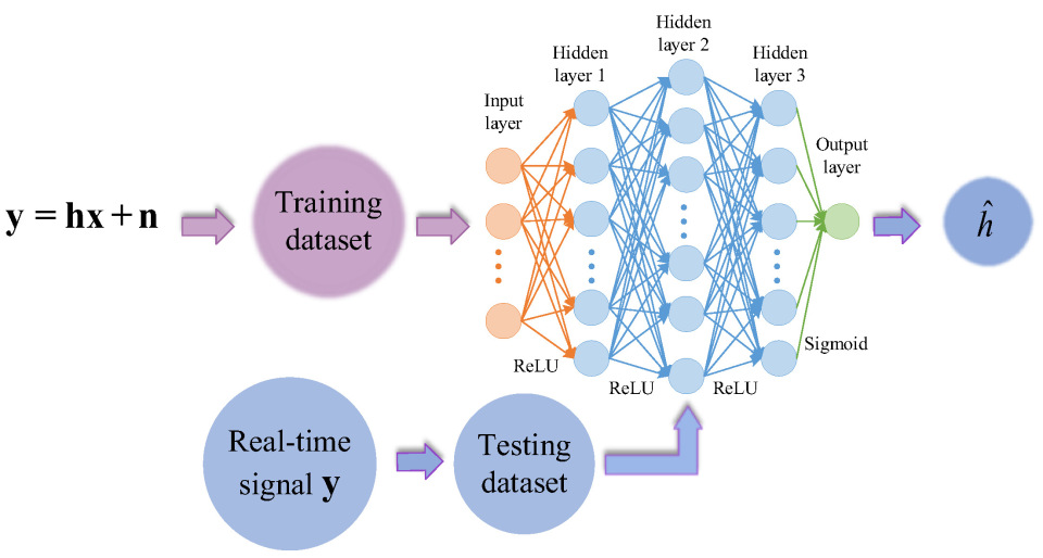
In this paper, the DNN-based underwater joint channel estimation model consists of an input layer, three hidden layers, and an output layer. The estimation model uses the ReLU function as the activation function in the hidden layer and the Sigmoid function in the output layer to map the output to the interval ( 0 , 1 ) , thus improving the autonomous learning ability of the DNN estimation model. The DNN channel estimation scheme is shown in Figure 3, where y is the received data of the autoencoder receiver, as given by Equation (8). The training dataset for the DNN estimation model is composed of received data y and channel fading data h, which are labels for the DNN model. By training the model, the mapping relationship between the received signal and channel fading is obtained; then, the instantaneous fading h ^ of the underwater channel is accurately estimated online.
Using the DNN model to achieve channel estimation for underwater wireless optical communication, in the training process of DNN, in order to minimize the error between the true value h and the predicted value h ^ , the MSE is used as the loss function of the network model:
L MSE = 1 m i = 1 m ( h i h i ) 2
where h i is the input label used for training the DNN model, which is the true value; h i is the output value recovered by the DNN model, which is the predicted value; and m is the number of samples.

3.3. Adaptive Transmission of Autoencoder Groups

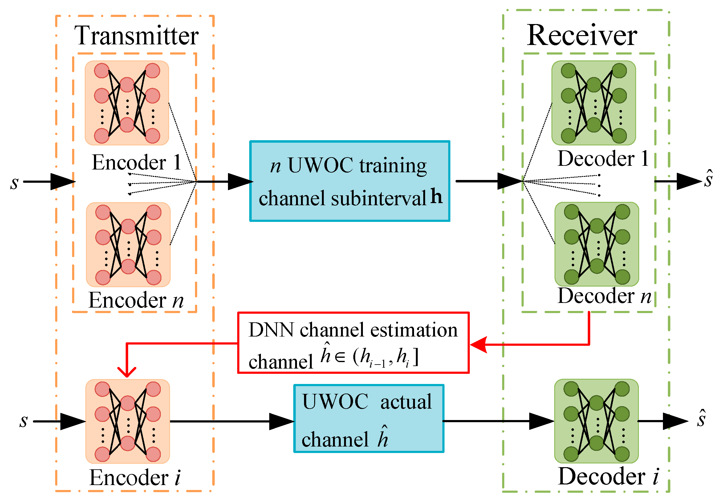
In this section, an adaptive transmission scheme for underwater autoencoder groups based on channel estimation is proposed with the aim of improving the reliability of the UWOC system under different actual underwater channel conditions, as shown in Figure 4.
The underwater channel fading h = [ h min , h max ] is divided into n sub-intervals, and an autoencoder is trained in each channel sub-interval. These n trained encoders and decoders form an autoencoder group. Based on the instantaneous state information of the channel, the corresponding autoencoder in the autoencoder group will be chosen for adaptive transmission. The channel fading interval can be expressed as
h = [ [ h min , h 1 ] , ( h 1 , h 2 ] , , ( h n 1 , h max ] ] N   sub-intervals
During the online transmission, the receiver feeds back the estimated instantaneous channel fading h ^ to the transmitter. If the channel fading h ^ is within the i-th sub-interval of h , select the i-th pair of encoders and decoders to send and receive data. Algorithm 1 presents the main steps of the proposed autoencoder group adaptive transmission scheme based on underwater channel estimation.
Algorithm 1. Adaptive Transmission Using Real-Time Channel Estimation
1Input: n sub-intervals of channel fading, n pairs for encoder and decoder.
2Output: The i-th pair of encoders and decoders used for sending and receiving data, estimated actual channel fading value h ^ .
3Start
41. (Offline) Training n pairs of encoders and decoders on n channel sub-intervals using a large training dataset consisting of all M possible one-hot vectors;
52. (Online) Using DNN model to estimate the instantaneous underwater channel fading h at the receiver and feed it back to the transmitter;
63. (Online) if  h ^  lies in the i-th sub-interval then
7                      Select the i-th pair of encoder and decoder to send and receive data;
8                   end if
94. (Online) Estimate the real-time underwater channel fading;
10if The estimated value has changed from the current sub-interval to another one then
11    Switch to the appropriate encoder and decoder in the group for data transmission.
12end if
13End
The robustness of the adaptive transmission scheme for autoencoder groups based on underwater channel estimation comes at the cost of using multiple pairs of encoder–decoder pairs instead of a single pair, which increases the deployment cost of the system. Therefore, the UWOC system based on autoencoders needs to consider the minimum number of encoder–decoder pairs while meeting the target performance. The optimal number of encoder–decoder pairs for an autoencoder group is found using the target average bit error rate P e t as the criterion for the UWOC system, and the minimum number of encoder–decoder pairs (i.e., the number of channel sub-intervals) is found to meet the bit error rate constraints under different channel conditions. Therefore, the optimal number of encoder–decoder pairs problem can be expressed as
min n s . t . P ¯ e P e t
where n is the number of pairs of encoders and decoders, P ¯ e represents the error rate under different channel conditions, and P e t is the target average bit error rate.
It is worth noting that in the optimization problem of the number of encoders in the autoencoder group, the minimum number of encoder–decoder pairs should be found under different channel conditions. As the number of encoders gradually increases, the system performance designed under different channel conditions improves. However, when the number of encoders increases to a certain value, the system performance will no longer improve, and at the same time, the complexity will increase. Therefore, it is necessary to find the optimal number of encoder–decoder pairs to balance the system deployment costs and expected performance.

4. Simulation Results and Analysis

In this section, we evaluate the numerical results of the proposed adaptive transmission scheme of an autoencoder group based on an underwater channel estimator.
The UWOC performances of the DL-based communication system were evaluated by simulations using Keras 2.15 and TensorFlow 2.15.0 frameworks. We used Adam [24] optimizer and Dropout [23] regularization methods to randomly discard some neurons in the hidden layer, thus avoiding the network getting locally optimized and overfitting during the training process. The simulated and theoretical number of training parameters in autoencoder M = 64 are shown in Table 2. For adaptive transmission, DNN channel estimation is also required, and the number of floating-point operations for DNN channel estimation mainly depends on factors such as the network structure, the size of the training data, and the optimization algorithm used in the training process. Normally, the floating-point operand (FLOPS) for DNN channel estimation is N D N N = 2 ( N i n 1 ) N o u t , where N in and N out are the number of neurons input and output by the DNN channel estimation model, respectively.

4.1. Performance Analysis of DNN Estimation Algorithm for Underwater Channel

The network training hyperparameter settings for the DNN channel estimation model are shown in Table 3 [19,25]. In the simulation, the training intensity scintillation index σ I T 2 = 0.2 , underwater absorption coefficient a = 0.114   m 1 , scattering coefficient b = 0.037   m 1 , link distance L = 15   m , and training signal to noise ratio (SNR) is SNR T = 20   dB .
The training loss of a DNN estimation model refers to the difference between the estimated value and the true value, which is computed using the MSE loss function (12). This value reflects the performance of the DNN model during the training process. The validation loss is usually used to evaluate the generalization ability of the model, that is, the predictive ability of the model for new samples. By monitoring the validation loss, overfitting or underfitting of the model can be detected in a timely manner.
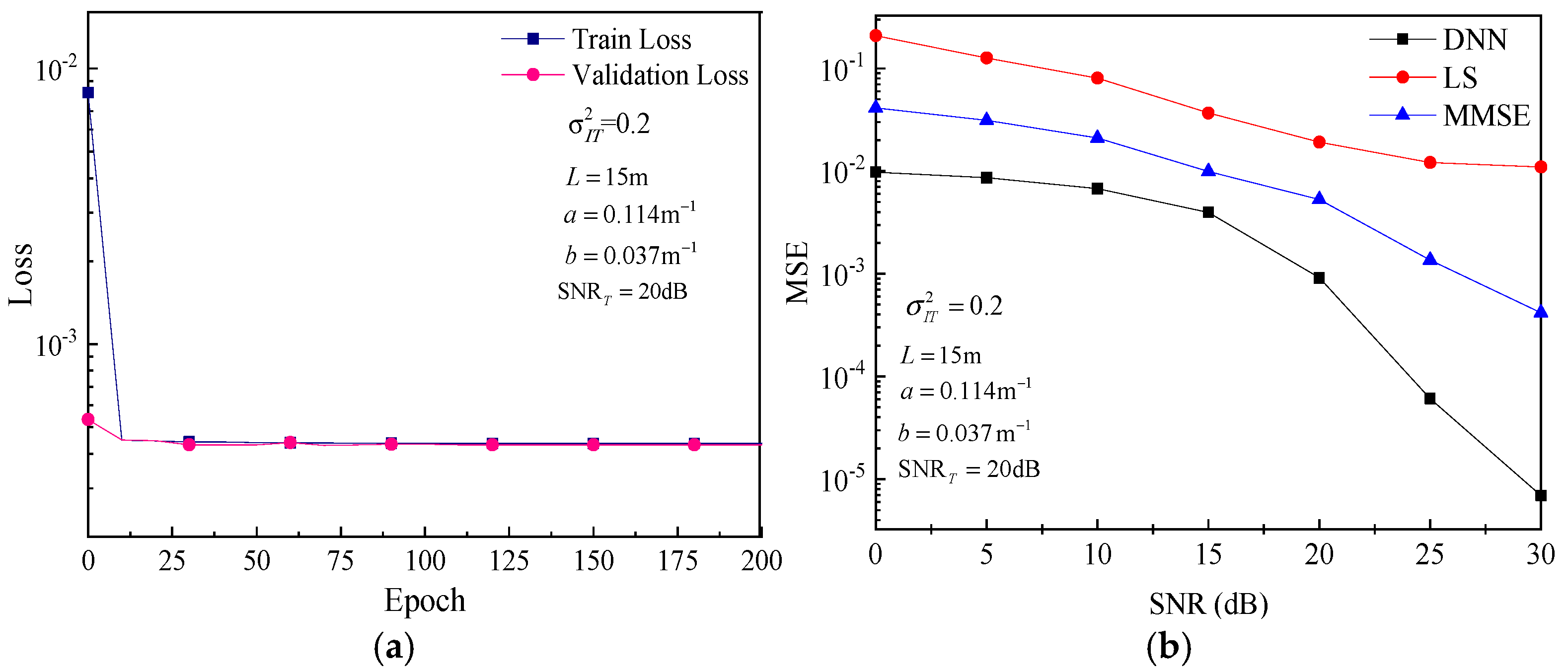
In a typical clear seawater environment considering link loss and Gamma–Gamma turbulence, the autoencoder uses a one-hot vector of M = 64 for transmission, and the received signal obtained is y . The DNN training dataset consists of simulated channel fading data h and received data y , and simulated channel fading data h is generated by Equation (1). The convergence comparison curve between the DNN training loss and validation loss is shown in Figure 5a. It can be seen that as the training iterations epochs increase, the loss gradually decreases, and the fitting degree of the DNN model to the training data gradually improves. The training loss rapidly decreases between 0 and 20 epochs; then, the loss value slowly decreases and gradually becomes flat. Finally, the network converges after 100 epochs of training, and the training loss value reaches 4.36 × 10 4 . In addition, after 20 epochs, there is almost no difference between the training loss and the validation loss; this indicates that the deep neural network (DNN) estimation model fits very well and has a good generalization performance.
Meanwhile, in order to evaluate the performance of the proposed DNN model in real-time underwater channel estimation, we trained and tested the DNN channel estimation model in a clear seawater environment and compared it with the mean square error of traditional LS and MMSE channel estimation methods through simulations. From Figure 5b, it can be seen that the MSE obtained through the three channel estimation methods of DNN, LS, and MMSE gradually decreases with the increase in the signal-to-noise ratio. Compared with traditional LS and MMSE channel estimation, the DNN channel estimation model has the lowest MSE, indicating that its estimation accuracy is the highest. The results indicate that using the DNN channel estimator to estimate underwater channel fading parameters has good estimation accuracy and further demonstrate that the DNN estimator can obtain more accurate channel characteristics by learning the mapping relationship between received signals and channels using deep neural networks. In other words, the DNN estimator has a strong learning ability for UWOC using deep neural networks.

4.2. Performance Analysis of Autoencoder Transmission

4.2.1. Non-Adaptive Transmission

In order to compare the performance of underwater autoencoders with traditional multiple phase shift keying (MPSK) modulation communication systems, Figure 6 shows the comparison of the BER between the autoencoder one-hot vector non-adaptive transmission scheme and the traditional MPSK modulation schemes. Under the UWOC joint channel conditions of light intensity fluctuation variance σ I 2 = 0.2 , underwater absorption coefficient a = 0.114   m 1 , scattering coefficient b = 0.037   m 1 , link distance L = 15   m , and training signal-to-noise ratio SNR T = 20   dB , the N , k autoencoder was trained and fixed neural network parameters were obtained. The number of discrete channel neurons in the simulation was N = 7 , and the bit signals were k = 2 , 3 , 4 , 5 , 6 .
From Figure 6, it can be seen that the bit error rate of the underwater autoencoder decreases with the increase in the signal-to-noise ratio at the receiver. When the dimension M  ( M = 2 k ) of the one-hot vector changes from 64 to 4, the bit error rate of the traditional one-hot vector scheme decreases, and the transmission rate also decreases accordingly. This phenomenon is more pronounced under high signal-to-noise ratio conditions. On the other hand, the bit error rate performance of underwater autoencoders is much better than that of traditional UWOC communication systems modulated by MPSK. At a signal-to-noise ratio of 25 dB, the bit error rate of traditional BPSK modulation communication is 0.00944, and the bit error rate of 16PSK modulation communication is 0.10125. However, the communication bit error rate of autoencoders using M = 64 solitary heat vectors for transmission can reach 9.4 × 10 5 . This indicates that underwater communication systems based on deep learning can learn and extract the features of encoder and decoder functions without any prior knowledge and can achieve lower bit error rates than traditional modulation scheme communication systems.

4.2.2. Adaptive Transmission

In order to maximize the end-to-end performance of the UWOC system based on autoencoders, the channel model of the autoencoder during training should match the actual transmission channel of the UWOC system. However, for actual UWOC systems, the channels are not fully known and vary randomly. Therefore, for each new channel condition, it is necessary to retrain the autoencoder from scratch, which greatly limits the availability and reliability of the link. Therefore, this section proposes an adaptive transmission scheme that adapts to different channel conditions by training an autoencoder group composed of multiple pairs of codecs. In the simulation, the underwater channel can be divided into n sub-intervals based on the variance of light intensity fluctuations, with each sub-interval corresponding to an encoder. The autoencoders are trained separately in different variance intervals of light intensity fluctuations. During online transmission, the trained autoencoders are adaptively selected based on the estimated variance of instantaneous light intensity fluctuations in the underwater channel to achieve adaptive transmission. The parameter settings for channel sub-intervals in different marine environments are shown in Table 4. In clear seawater environments, the channel is divided into eight sub-intervals based on the variance of light intensity fluctuations, while in coastal seawater environments, the channel is divided into six sub-intervals based on the variance of light intensity fluctuations.
Table 4 shows the parameter settings of the scintillation index σ I T 2 for channel sub-intervals in different marine environments. The σ I T 2 value that is too large means stronger turbulence, but it can also affect the convergence of loss in network training. Therefore, in simulation, we set the turbulence intensity training set as σ I T 2 [ 0.2 , 1 ] in a clear seawater environment. Similarly, in coastal seawater environments, the turbulence intensity training set is σ I T 2 [ 0.2 , 0.8 ] . By using Equations (1), (2) and (5), we can obtain the sub-intervals of channel fading h . The encoders and decoders are trained separately in different sub-intervals of the channel, and then the corresponding trained encoder is adaptively selected based on the instantaneous estimation information of the underwater channel during the online process to achieve adaptive transmission.
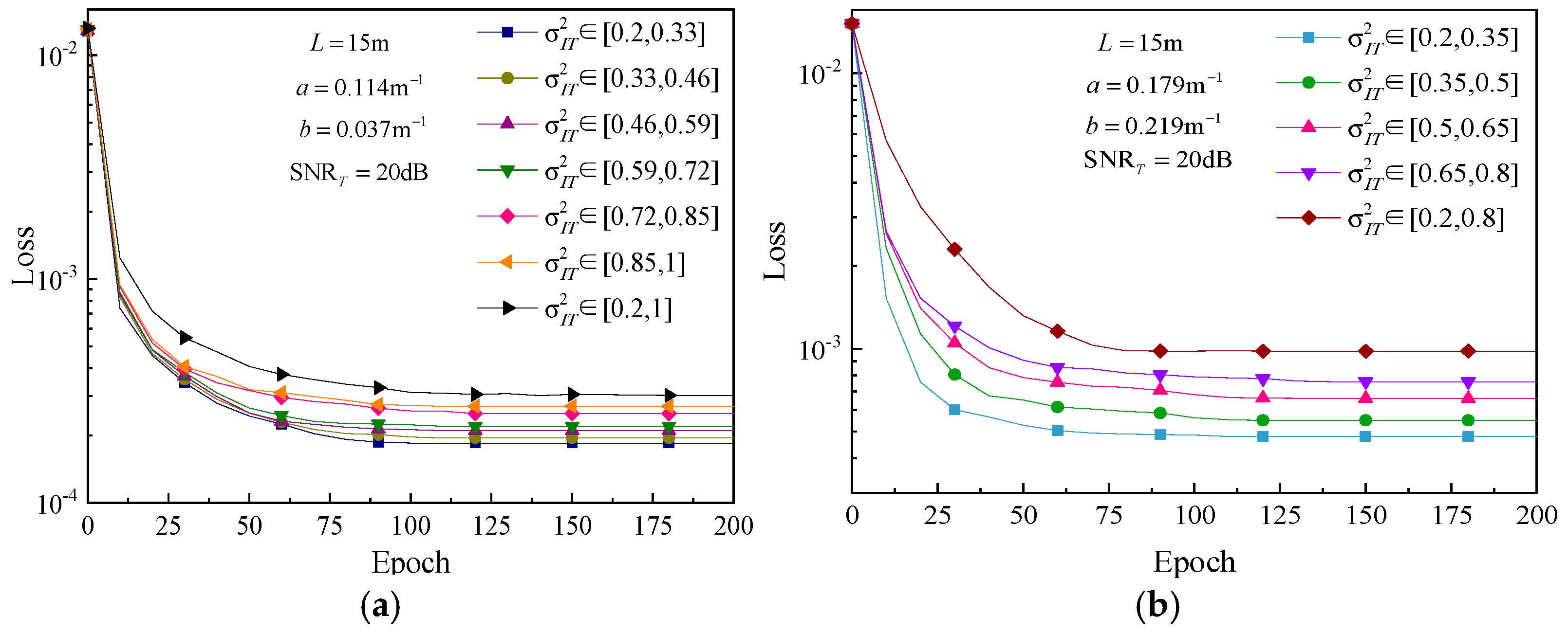
Figure 7 shows the loss curves of the autoencoder training in different turbulence intensity sub-intervals of underwater channels. In a clear seawater environment, if the number of intervals between channels was n = 6, the turbulence intensity training set σ I T 2 [ 0.2 , 1 ] was evenly divided with a step size of 0.13, as shown in Table 4. In a costal seawater environment, the turbulence intensity training set σ I T 2 [ 0.2 , 0.8 ] was divided with a step size of 0.15, that is, the number of channel sub-intervals was n = 4 . The autoencoder was trained within each turbulent channel sub-interval, and the training loss curve is given in Figure 7. It can be seen that the maximum loss occurs for the turbulence intensity training set σ I T 2 [ 0.2 , 1 ] in Figure 7a. In addition, during the training of the autoencoder group, a larger step size in the channel sub-interval may lead to gradient explosion, increased training loss, and cause overfitting of the network. However, a smaller step size may also lead to gradient vanishing, slow convergence speed, and underfitting of the network. Therefore, selecting an optimal step size to divide the turbulent channel sub-intervals for training the autoencoder group can not only accelerate the convergence speed of the network and reduce training losses but also obtain a robust network model.
To obtain the optimal number of encoders and decoders under different UWOC channel conditions, we investigated the error rate performance of the autoencoder group adaptive-transmission-based DNN channel estimator, which is shown in Figure 8. In the simulation, n is the number of encoders and decoders, which corresponds to dividing the training ocean turbulence intensity set into n sub-intervals and training one autoencoder on each interval.
In Figure 8, when only one pair of encoder and decoder is used, i.e., n = 1 , the UWOC system based on the autoencoder can be considered as non-adaptive transmission, and the system’s error rate performance is the worst at this time. In clear seawater environments, compared with the non-adaptive transmission scheme, the adaptive transmission scheme of the autoencoder group ( n = 6 ) can achieve a 10 dB SNR gain at BER = 4.2 × 10 5 . However, adding the number of sub-intervals (or equal number of encoder and decoder pairs) after a given number (i.e., n = 6) does not always result in an improvement in the system performance. Similarly, in a coastal seawater environment, the error rate performance is optimal when n = 4 . This indicates that when the channel sub-interval is short, the n pairs of encoder and decoder trained over close sub-intervals (i.e., nearly the same channel conditions) provide the same performance, while also increasing the complexity of dynamically selecting the optimal number. However, if the sub-interval of the channel is wide, it may lead to a decrease in the accuracy of selecting the corresponding autoencoder during adaptive transmission, thereby increasing the bit error rate.

5. Discussion and Conclusions

In this paper, in order to improve the reliability of UWOC systems in complex underwater environments, an adaptive transmission scheme for autoencoder groups based on DNN channel estimation is proposed. The performance of the UWOC system based on channel estimation is evaluated using an autoencoder group adaptive transmission scheme. Compared with traditional estimation methods, the DNN estimation has the best MSE estimation performance and is more suitable for estimating time-varying underwater channel fading parameters. Compared with non-adaptive transmission, UWOC systems based on autoencoder group adaptive transmission can achieve lower bit error rates in different underwater channel scenarios. In addition, under the condition of meeting the target error rate, the optimal number of autoencoders for the adaptive transmission scheme can be selected to balance the system performance and system complexity.
To improve the transmission reliability of underwater optical communication systems based on autoencoder groups under different channel conditions, this paper proposes an adaptive transmission scheme for autoencoder groups based on underwater channel estimation. We have achieved certain results, but there are still problems that need to be explored and studied. At present, although the performance of underwater wireless communication systems based on DNN channel estimation is superior, the computational complexity is high. In the future, lightweight neural network architectures can be explored to achieve lower complexity and power consumption. In addition, the article conducted theoretical research without conducting experimental studies. In the future, experiments can be conducted in real underwater scenarios by building an experimental platform to consider the feasibility of adaptive transmission schemes for autoencoders in communication systems under different ocean conditions, link distances, and turbulence intensity.

Author Contributions

Conceptualization, D.C.; methodology, D.C.; investigation, D.C.; formal analysis, D.C.; funding acquisition, D.C.; writing—original draft preparation, D.C. and J.L.; data curation, J.L.; supervision, J.L.; writing—review and editing, R.W.; validation, R.W. All authors have read and agreed to the published version of the manuscript.

Funding

This work is supported by the National Natural Science Foundation of China (No. 62371390), the Key Research and Development Program of Shaanxi Province of China (No. 2023-YBGY-039, No. 2020-GY-036), and the Xi’an Science and Technology Bureau Program (No. 2019-GXYD14.21).

Institutional Review Board Statement

Not applicable.

Informed Consent Statement

Not applicable.

Data Availability Statement

Data are contained within the article.

Conflicts of Interest

Author Dan Chen was employed by Xi’an University of Technology. The remaining authors declare that the research was conducted in the absence of any commercial or financial relationships that could be construed as a potential conflict of interest.

References

  1. Al-Shamma’a, A.I.; Shaw, A.; Saman, S. Propagation of electromagnetic waves at MHz frequencies through seawater. IEEE Trans. Antennas Propag. 2004, 52, 2843–2849. [Google Scholar] [CrossRef]
  2. Sun, X.; Kang, C.H.; Kong, M.; Alkhazragi, O.; Guo, Y.; Ouhssain, M.; Weng, Y.; Jones, B.H.; Ng, T.K.; Ooi, B.S. A review on practical considerations and solutions in underwater wireless optical communication. J. Light. Technol. 2020, 38, 421–431. [Google Scholar] [CrossRef]
  3. Xu, J. Underwater wireless optical communication: Why, what, and how? Chin. Opt. Lett. 2019, 17, 100007. [Google Scholar] [CrossRef]
  4. Alipour, A.; Mir, A. On the performance of blue–green waves propagation through underwater optical wireless communication system. Photonic Netw. Commun. 2018, 36, 309–315. [Google Scholar] [CrossRef]
  5. Miramirkhani, F.; Uysal, M. Visible light communication channel modeling for underwater environments with blocking and shadowing. IEEE Access 2017, 6, 1082–1090. [Google Scholar] [CrossRef]
  6. Ji, X.Y.; Yin, H.; Jing, L.; Liang, Y.; Wang, J. Performance analysis of underwater wireless optical communication system with strong turbulence channels based on strong fluctuation theory. Acta Opt. Sin. 2022, 42, 9–16. [Google Scholar] [CrossRef]
  7. Jamali, M.V.; Mirani, A.; Parsay, A.; Abolhassani, B.; Nabavi, P.; Chizari, A.; Khorramshahi, P.; Abdollahramezani, S.; Salehi, J.A. Statistical studies of fading in underwater wireless optical channels in the presence of air bubble, temperature, and salinity random variations. IEEE Trans. Commun. 2018, 66, 4706–4723. [Google Scholar] [CrossRef]
  8. Talaei Khoei, T.; Ould Slimane, H.; Kaabouch, N. Deep learning: Systematic review, models, challenges, and research directions. Neural Comput. Appl. 2023, 35, 23103–23124. [Google Scholar] [CrossRef]
  9. Qin, Z.; Ye, H.; Li, G.Y.; Juang, B.H.F. Deep learning in physical layer communications. IEEE Wirel. Commun. 2019, 26, 93–99. [Google Scholar] [CrossRef]
  10. O’Shea, T.J.; Karra, K.; Clancy, T.C. Learning to communicate: Channel auto-encoders, domain specific regularizers, and attention. In Proceedings of the 2016 IEEE International Symposium on Signal Processing and Information Technology (ISSPIT), Limassol, Cyprus, 12–14 December 2016; pp. 223–228. [Google Scholar] [CrossRef]
  11. Mallik, W.; Jaiman, R.K.; Jelovica, J. Predicting transmission loss in underwater acoustics using convolutional recurrent autoencoder network. J. Acoust. Soc. Am. 2022, 152, 1627–1638. [Google Scholar] [CrossRef] [PubMed]
  12. Mirkarimi, F.; Tellambura, C.; Li, G.Y. Deep MMSE estimation for data detection. IEEE Commun. Lett. 2022, 27, 180–184. [Google Scholar] [CrossRef]
  13. Dörner, S.; Cammerer, S.; Hoydis, J.; Ten Brink, S. Deep learning based communication over the air. IEEE J. Sel. Top. Signal Process. 2017, 12, 132–143. [Google Scholar] [CrossRef]
  14. Aoudia, F.A.; Hoydis, J. End-to-end learning of communications systems without a channel model. In Proceedings of the 52nd Asilomar Conference on Signals, Systems, and Computers, Pacific Grove, CA, USA, 28–31 October 2018; pp. 298–303. [Google Scholar] [CrossRef]
  15. Lu, H.; Jiang, M.; Cheng, J. Deep learning aided robust joint channel classification, channel estimation, and signal detection for underwater optical communication. IEEE Trans. Commun. 2020, 69, 2290–2303. [Google Scholar] [CrossRef]
  16. Gabriel, C.; Khalighi, M.A.; Bourennane, S.; Léon, P.; Rigaud, V. Monte-Carlo-based channel characterization for underwater optical communication systems. J. Opt. Commun. Netw. 2013, 5, 1–12. [Google Scholar] [CrossRef]
  17. Zeng, Z.; Fu, S.; Zhang, H.; Dong, Y.; Cheng, J. A survey of underwater optical wireless communications. IEEE Commun. Surv. Tutor. 2016, 19, 204–238. [Google Scholar] [CrossRef]
  18. Tang, S.; Dong, Y.; Zhang, X. Impulse response modeling for underwater wireless optical communication links. IEEE Trans. Commun. 2013, 62, 226–234. [Google Scholar] [CrossRef]
  19. Shi, J.; Huang, A.; Tao, L. Deep learning aided channel estimation and signal detection for underwater optical communication. Chin. J. Lasers 2022, 49, 110–117. [Google Scholar] [CrossRef]
  20. Ata, Y.; Kiasaleh, K. Analysis of optical wireless communication links in turbulent underwater channels with wide range of water parameters. IEEE Trans. Veh. Technol. 2023, 72, 6363–6374. [Google Scholar] [CrossRef]
  21. Andrews, L.C.; Beason, M.K. Laser Beam Propagation in Random Media: New and Advanced Topics; SPIE Publications: Bellingham, WA, USA, 2023. [Google Scholar]
  22. Goodfellow, I.; Bengio, Y.; Courville, A.; Bengio, Y. Deep Learning; MIT Press: Cambridge, MA, USA, 2016. [Google Scholar] [CrossRef]
  23. Srivastava, N.; Hinton, G.; Krizhevsky, A.; Sutskever, I.; Salakhutdinov, R. Dropout: A simple way to prevent neural networks from overfitting. J. Mach. Learn. Res. 2014, 15, 1929–1958. Available online: https://dl.acm.org/doi/abs/10.5555/2627435.2670313 (accessed on 21 August 2025).
  24. Kingma, D.P.; Ba, J. Adam: A method for stochastic optimization. arXiv 2014, arXiv:1412.6980. [Google Scholar] [CrossRef]
  25. Hu, J.; Bai, Z.; Yang, J.; Cai, Y.; Zhou, D.; Wang, Y.; Kwak, K. DNN and LS Based Channel Estimation in OTFS System. In Proceedings of the 2023 IEEE 23rd International Conference on Communication Technology (ICCT), Wuxi, China, 20–22 October 2023; pp. 106–110. [Google Scholar] [CrossRef]
Figure 1. Autoencoder model.
Photonics 12 00865 g001
Figure 2. UWOC system based on autoencoder.
Photonics 12 00865 g002
Figure 3. DNN channel estimation scheme.
Photonics 12 00865 g003
Figure 4. Adaptive transmission scheme for underwater autoencoder group based on channel estimation.
Photonics 12 00865 g004
Figure 5. Loss curve and MSE performance curve of DNN channel estimation. (a) Loss curve; (b) MSE performance curve of different channel estimation methods.
Photonics 12 00865 g005
Figure 6. Comparison of the BER between the autoencoder one-hot vector non-adaptive transmission scheme and the traditional MPSK modulation schemes.
Photonics 12 00865 g006
Figure 7. Network training loss of autoencoder group at different channel sub-intervals. (a) Clear seawater; (b) costal seawater.
Photonics 12 00865 g007
Figure 8. BER of autoencoder group adaptive transmission scheme under different channel sub-intervals and SNR. (a) Clear seawater; (b) coastal seawater.
Photonics 12 00865 g008
Table 1. Absorption, scattering, and attenuation coefficients in different types of water.
Water Type a ( λ )   ( m 1 ) b ( λ )   ( m 1 ) c ( λ )   ( m 1 )
Pure sea water0.0530.0030.056
Clear ocean water0.1140.0370.151
Costal ocean water0.1790.2190.398
Turbid harbor water0.2951.8752.17
Table 2. Training parameters of autoencoder.
Simulation ParametersOutput ShapeTheoretical Parameters
Transmitter
Input64 { 0 , 1 } M M
Dense (Reu layer)4160 M ( M + 1 ) ( M + N )
Dense (linear layer)455 N
Normalization14 N 2 N
Underwater channel
h = h c h t 14 N 2 N
Additive white Gaussian noise14 N 2 N
Receiver
Dense (ReLU layer)512 M M ( N + 1 )
Dense (Softmax layer)4160 M M ( M + 1 )
Table 3. Training hyperparameters for DNN channel.
ParameterValue
OptimizerAdam
Loss function MSE
Activation functionReLU, Sigmoid
Number of training samples 10 6
Number of test samples 10 5
Number of input layer neurons7
Number of neurons in hidden layer 1500
Number of neurons in hidden layer 2250
Number of neurons in hidden layer 3120
Number of output layer neurons1
Maximum number of iterations epochs200
Batch size quantity32
Table 4. Parameter settings of signaling sub-intervals in different marine environments.
Seawater TypenChannel Sub-Intervals
Clear seawater1 σ I T 2 [ 0.2 , 1 ]
2 σ I T 2 [ [ 0.2 , 0.6 ] , ( 0.6 , 1 ] ]
3 σ I T 2 [ [ 0.2 , 0.47 ] , ( 0.47 , 0.74 ] , ( 0.74 , 1 ] ]
4 σ I T 2 [ [ 0.2 , 0.4 ] , ( 0.4 , 0.6 ] , ( 0.7 , 0.8 ] , ( 0.8 , 1 ] ]
5 σ I T 2 [ [ 0.2 , 0.36 ] , ( 0.36 , 0.52 ] , ( 0.52 , 0.68 ] , ( 0.68 , 0.84 ] , ( 0.84 , 1 ] ]
6 σ I T 2 [ [ 0.2 , 0.33 ] , ( 0.33 , 0.46 ] , ( 0.46 , 0.59 ] , ( 0.59 , 0.72 ] , ( 0.72 , 0.85 ] , ( 0.85 , 1 ] ]
7 σ I T 2 [ [ 0.2 , 0.31 ] , ( 0.31 , 0.42 ] , ( 0.42 , 0.53 ] , ( 0.53 , 0.64 ] , ( 0.64 , 0.75 ] , ( 0.75 , 0.86 ] , ( 0.86 , 1 ] ]
8 σ I T 2 [ [ 0.2 , 0.3 ] , ( 0.3 , 0.4 ] , ( 0.4 , 0.5 ] , ( 0.5 , 0.6 ] , ( 0.6 , 0.7 ] , ( 0.7 , 0.8 ] , ( 0.8 , 0.9 ] , ( 0.9 , 1 ] ]
Costal seawater1 σ I T 2 [ 0.2 , 0.8 ]
2 σ I T 2 [ [ 0.2 , 0.5 ] , ( 0.5 , 0.8 ] ]
3 σ I T 2 [ [ 0.2 , 0.4 ] , ( 0.4 , 0.6 ] , ( 0.6 , 0.8 ] ]
4 σ I T 2 [ [ 0.2 , 0.35 ] , ( 0.35 , 0.5 ] , ( 0.5 , 0.65 ] , ( 0.65 , 0.8 ] ]
5 σ I T 2 [ [ 0.2 , 0.32 ] , ( 0.32 , 0.44 ] , ( 0.44 , 0.56 ] , ( 0.56 , 0.68 ] , ( 0.68 , 0.8 ] ]
6 σ I T 2 [ [ 0.2 , 0.3 ] , ( 0.3 , 0.4 ] , ( 0.4 , 0.5 ] , ( 0.5 , 0.6 ] , ( 0.6 , 0.7 ] , ( 0.7 , 0.8 ] ]
Disclaimer/Publisher’s Note: The statements, opinions and data contained in all publications are solely those of the individual author(s) and contributor(s) and not of MDPI and/or the editor(s). MDPI and/or the editor(s) disclaim responsibility for any injury to people or property resulting from any ideas, methods, instructions or products referred to in the content.