Article

Complete Suppression of Color Dispersion in Quantum-Dot Backlights by Optimizing Optical Configuration of Films

School of Semiconductor Display Technology, Nano Convergence Technology Center, Hallym University, Chuncheon-si 24252, Gangwon-do, Republic of Korea
*
Author to whom correspondence should be addressed.
Photonics 2025, 12(9), 864; https://doi.org/10.3390/photonics12090864 (registering DOI)
Submission received: 28 July 2025 / Revised: 19 August 2025 / Accepted: 25 August 2025 / Published: 28 August 2025
(This article belongs to the Section Lasers, Light Sources and Sensors)

Abstract

This study investigated the optimization of optical film configurations to mitigate angular color deviation—a persistent challenge in quantum dot (QD) backlight displays. A white backlight was implemented by placing a yellow CdSe-based QD film on a blue edge-lit backlight, followed by various combinations of prism and diffusion films. Optical characteristics, including luminance, spectral distribution, and chromaticity coordinates, were systematically measured over a viewing-angle range of −70° to 70° for different film arrangements. Applying one or two prism films significantly enhanced normal luminance and improved color conversion efficiency by forming vertical optical cavities; however, this also introduced the side-lobe phenomenon, leading to color non-uniformity. Placing a diffusion film between the QD and prism films did not resolve these issues, whereas positioning it as the topmost layer above the prism films effectively eliminated color dispersion and produced a uniform luminance distribution. These results provide practical design guidelines for optimizing optical film stacks in QD-enhanced backlight units to achieve superior color uniformity in LCD displays.

1. Introduction

Liquid crystal displays (LCDs) have remained a dominant technology in the display industry for decades as a representative type of non-emissive display. Owing to advantages such as low power consumption, stable image quality, and high manufacturing productivity, LCDs are widely adopted in applications ranging from mobile devices and laptops to monitors, televisions, and outdoor information displays. A typical LCD comprises a backlight unit (BLU), a liquid crystal cell, bottom and top polarizers, and color filters. Among these components, the BLU functions as the light source for the display panel. The performance of an LCD—including its brightness, color reproduction, viewing angle, and energy efficiency—is largely governed by the BLU [1]. Consequently, extensive research has been devoted to optimizing BLU designs to enhance the overall performance and efficiency of LCDs. In particular, significant efforts have focused on developing novel white-light sources based on light-emitting diodes (LEDs) and color-conversion materials such as phosphors [2,3,4,5,6,7,8].
Ideally, the BLU spectrum should achieve a wide color gamut by exhibiting narrow emission peaks at the red, green, and blue primary wavelengths. However, phosphor-based light sources suffer from relatively broad emission spectra, which reduce color purity and, consequently, limit the achievable color gamut. In contrast, quantum dot (QD) BLUs, in which a QD film is incorporated, can produce sharp, narrow emission peaks at specific wavelengths by exploiting the tunable bandgap and inherently narrow emission characteristics of QDs. QDs are semiconductor nanoparticles only a few nanometers in size [9,10,11,12], and they can be fabricated into remote components, such as QD films in which the QDs are uniformly dispersed within a polymer matrix [13,14,15,16,17,18]. This configuration enables a significantly wider color gamut than conventional phosphor-based approaches, thereby greatly enhancing the color reproduction of displays [19,20,21,22,23,24,25,26,27,28,29,30,31,32,33,34,35,36,37].
Additionally, applying prism films with one-dimensional microscopic prism structures on the surface forms a vertical optical cavity between the bottom reflector and the prism films, inducing reciprocating light propagation. This configuration not only enhances brightness but also enables more efficient excitation of the QD film located within the optical cavity, thereby improving color conversion efficiency [38,39]. While a single prism film can collimate light in either the horizontal or vertical direction, arranging two prism films in a crossed configuration with their prism grooves oriented perpendicularly allows control of light in both directions. This results in higher brightness and further enhances the color conversion efficiency of the QD film [40].
Separately, although the red and green light emitted from QDs after absorbing blue backlight photons is initially isotropic, its directional characteristics can be altered through interactions with various optical films within the backlight system. Due to the thin-film geometry, the optical path length of the blue excitation light in the QD film varies with the incident angle, which in turn modulates the excitation probability of QDs and may induce color imbalance at oblique viewing angles [26,27,29]. Consequently, the spectral balance among the red, green, and blue components in the BLU can shift with viewing direction, leading to increased color dispersion and perceptible color shifts. Therefore, optimizing the optical design of QD-based BLUs is critical for minimizing such angular color deviations. Despite extensive research on QD BLUs, there are almost no quantitative reports on angular color dispersion, except for our previous studies [26,27,29]. A few studies have reported the angular color properties of QD-LED or QD-based micro-LED devices, which may be adopted in self-emitting displays [41,42,43].
Reducing angular color dispersion is crucial when integrating QD films into LCDs. In this study, we systematically investigated the influence of various optical configurations of QD-based BLUs on their optical performance. In particular, we examined the effects of the number and arrangement of optical films, as well as the transmittance and haze of diffusion films positioned above the yellow QD film. Based on this analysis, we identified optimized configurations that effectively minimize color deviations across viewing angles.

2. Experiments

In this study, a yellow QD film was placed on an edge-lit blue backlight to generate white light, and a combination of optical films was subsequently applied. The blue backlight, with a central emission wavelength of 455 nm and an area of 100 mm × 100 mm2, was purchased from Advanced Illumination (BT100100-455IC, Advanced Illumination, Rochester, VT, USA). The specific dimensions and a photograph of the blue BLU are provided in Figure S1. The yellow QD film consisted of red- and green-emitting CdSe-based QDs uniformly dispersed within a polymer matrix. Blue light emitted from the BLU excited the QD film, generating distinct emission peaks in the red and green spectral regions and, together with the residual blue component, producing white light.
In this study, the one-dimensional prism film was fabricated by cutting commercial prism films typically used in LCDs. The prism grooves have a vertex angle of 90°, and incident light is collimated in the forward direction through refraction at the inclined grooves with a 45° slope. To reduce color dispersion across viewing angles, two types of diffusion films with different haze values were employed. The films, with haze values of 97.07 and 67.96, are hereafter referred to as HighH (LGT075T, Simihui Electronic Materials Co., Ltd., Shenzhen, China) and LowH (LGT075T2, Simihui Electronic Materials Co., Ltd., Shenzhen, China), respectively. Haze affects the angular distribution and intensity of scattered light, thereby directly influencing viewing-angle characteristics and color dispersion. The haze and transmittance values of the two diffusion films, measured using a hazemeter (NDH-2000N, Nippon Denshoku, Tokyo, Japan), are summarized in Table 1. The microscopic structures of each diffusion film are shown in the microscope images in Figure S2.
For accurate measurements, the backlight was turned on and stabilized for a pre-aging period of 10 min prior to data acquisition. Luminance, chromaticity coordinates, and spectral distributions as a function of viewing angle were measured using a luminance meter (PR-670, Photo Research, Syracuse, NY, USA). The distance between the meter and the backlight was fixed at 95 cm. Viewing angles were controlled from −70° to 70° in 10° increments using a rotating table placed beneath the backlight. Color dispersion for each optical configuration was evaluated from the variations in chromaticity coordinates across viewing angles. Figure 1 presents schematic diagrams of the various optical film configurations on the blue backlight.
To compare color dispersion with that of a commercial product, measurements were conducted on a commercial 65-inch QD Mini-LED TV (C855, TCL, Huizhou, China) with the display panel removed. The optical structure of the product consisted, in the listed order, of a Mini-LED backlight, a diffusion sheet, a QD film, and a composite sheet, as illustrated in Figure S3. Measurements were performed over a viewing-angle range from −70° to +70° at a distance of 285 cm, corresponding to the average viewing distance for a 65-inch TV under typical usage conditions.

3. Results and Discussion

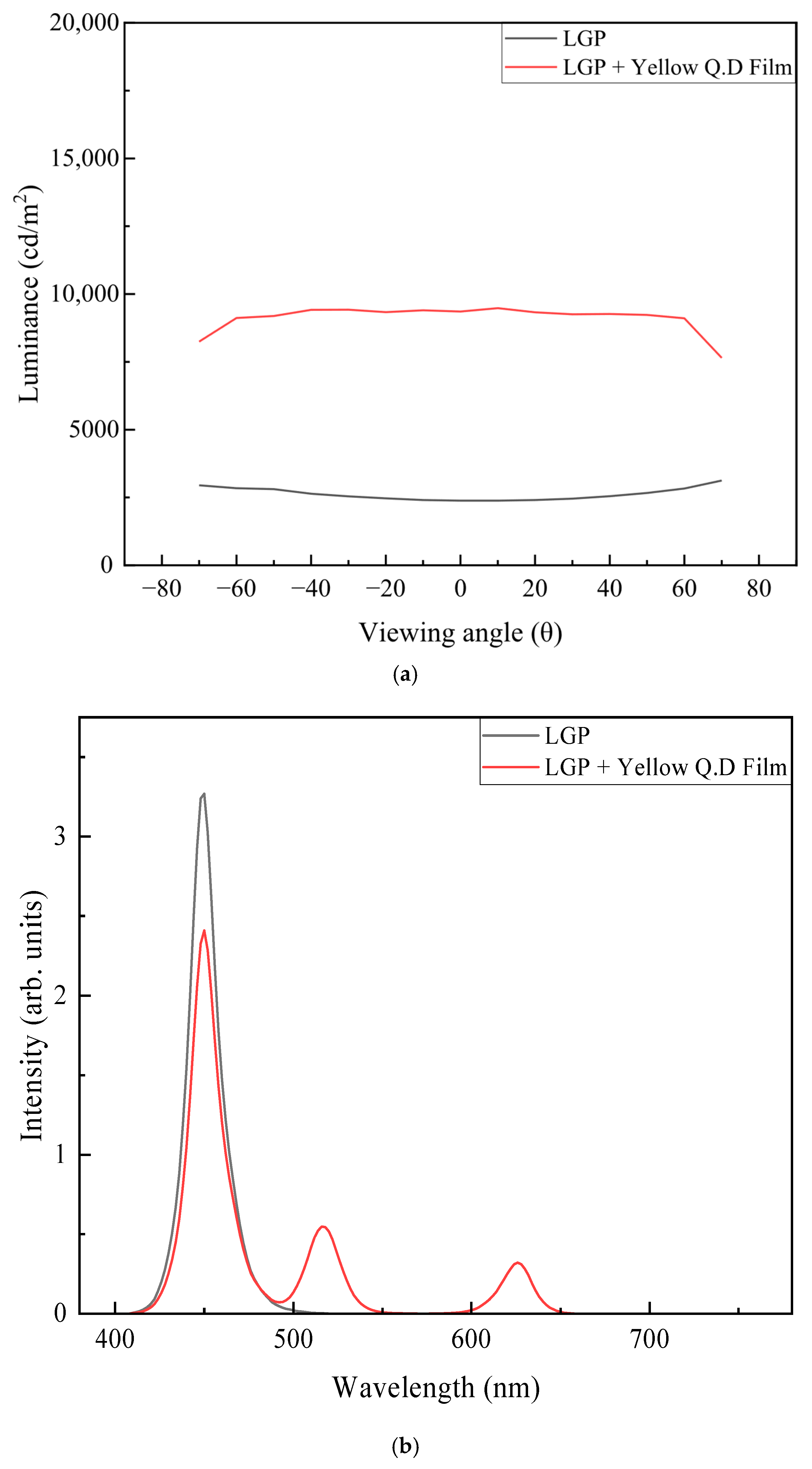
Figure 2a compares the angular dependence of luminance between the blue backlight and the white backlight incorporating the yellow QD film. Without the QD film, the luminance increased slightly at higher viewing angles due to scattering from dot patterns printed on the bottom surface of the light guide plate (LGP) to disrupt the total internal reflection. When the yellow QD film was applied, the luminance distribution became uniform owing to the scattering effect of the QDs, resulting in a quasi-Lambertian profile. Figure 2b compares the emission spectra of the backlight with and without the QD film. Blue light from the backlight excited the yellow QD film, producing additional emission peaks in the red (~635 nm) and green (~520 nm) spectral regions. As shown in Figure 2a, this spectral modification led to an increase in luminance of approximately 7000 cd/m2. This enhancement arises from the higher sensitivity of the human eye to green wavelengths, whereby the added green component increases the perceived luminance. Table 2 summarizes the luminance and chromaticity coordinates for all 18 configurations evaluated in this study.
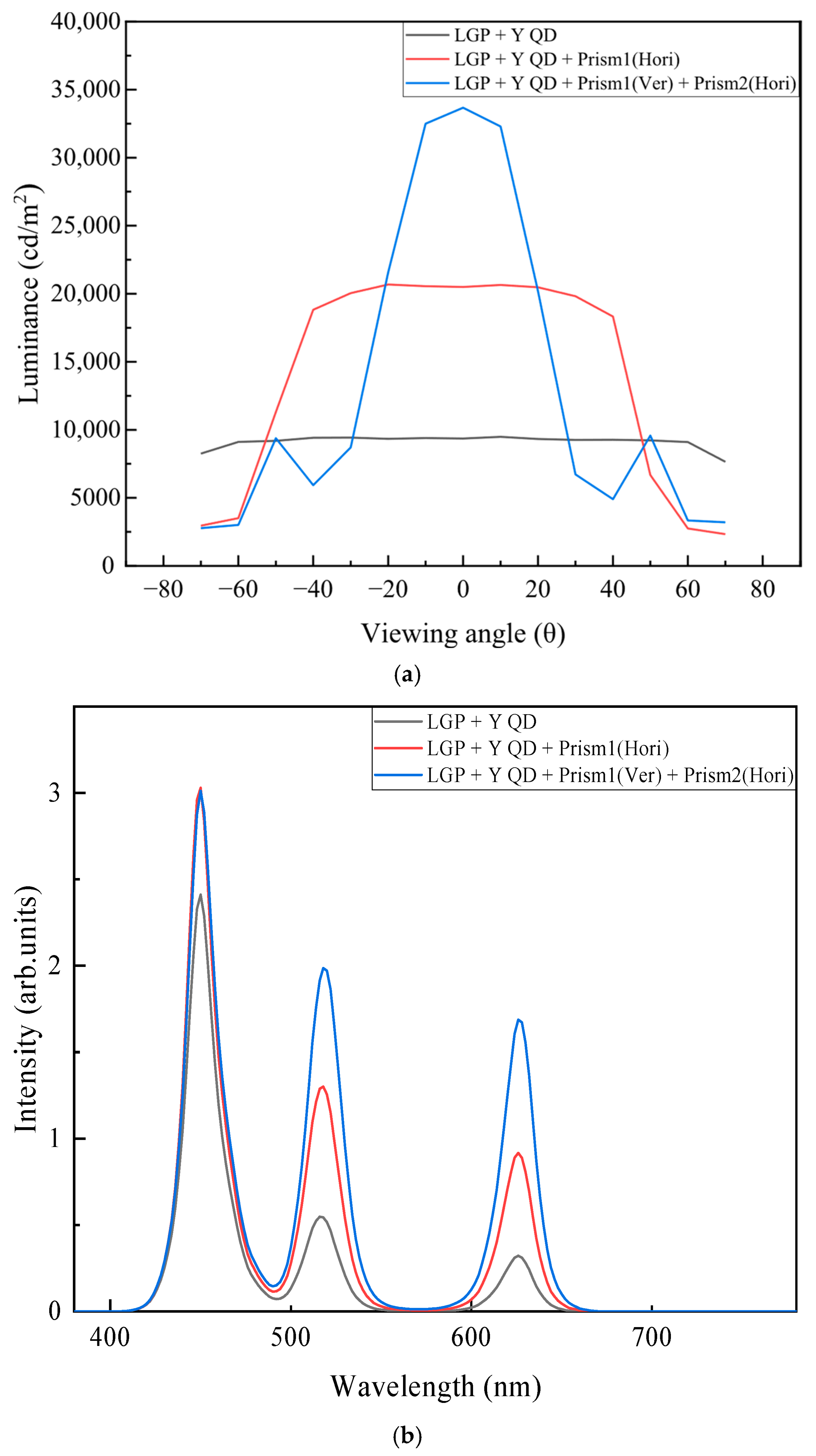
Next, we investigated the effect of prism film configuration on the optical characteristics of the QD BLU. The number of prism films (one or two) and the orientation of prism grooves (horizontal or vertical) placed on the yellow QD film were varied. Figure 3a compares the luminance obtained with a single prism film and with two crossed prism films, with the grooves of the top film oriented horizontally. When a single prism film was applied, the normal luminance increased by approximately 129% compared with the case without a prism film; stacking two films led to a further increase of about 56%. The viewing-angle distribution also became progressively narrower. However, when two films were stacked, an anomalous peak appeared at around 50°, attributed to the side-lobe phenomenon—an inherent limitation of prism films [44,45]. Prism films consist of triangular prism structures with a vertex angle of 90° and faces inclined at 45°, which refract incident light toward the normal direction to enhance frontal luminance. Nevertheless, some light is refracted at oblique angles, producing side lobes that can reduce color uniformity and distort viewing-angle characteristics, thus requiring the application of supplementary optical films to suppress this effect.
Figure 3b compares the spectra measured along the normal direction for the three optical film configurations shown in Figure 3a. As the number of prism films increased from one to two, the emission peaks in the red and green spectral regions increased progressively, indicating enhanced color conversion efficiency. This enhancement is primarily attributed to multiple reflections within the optical cavity formed by the reflector located beneath the LGP and the overlying prism films.
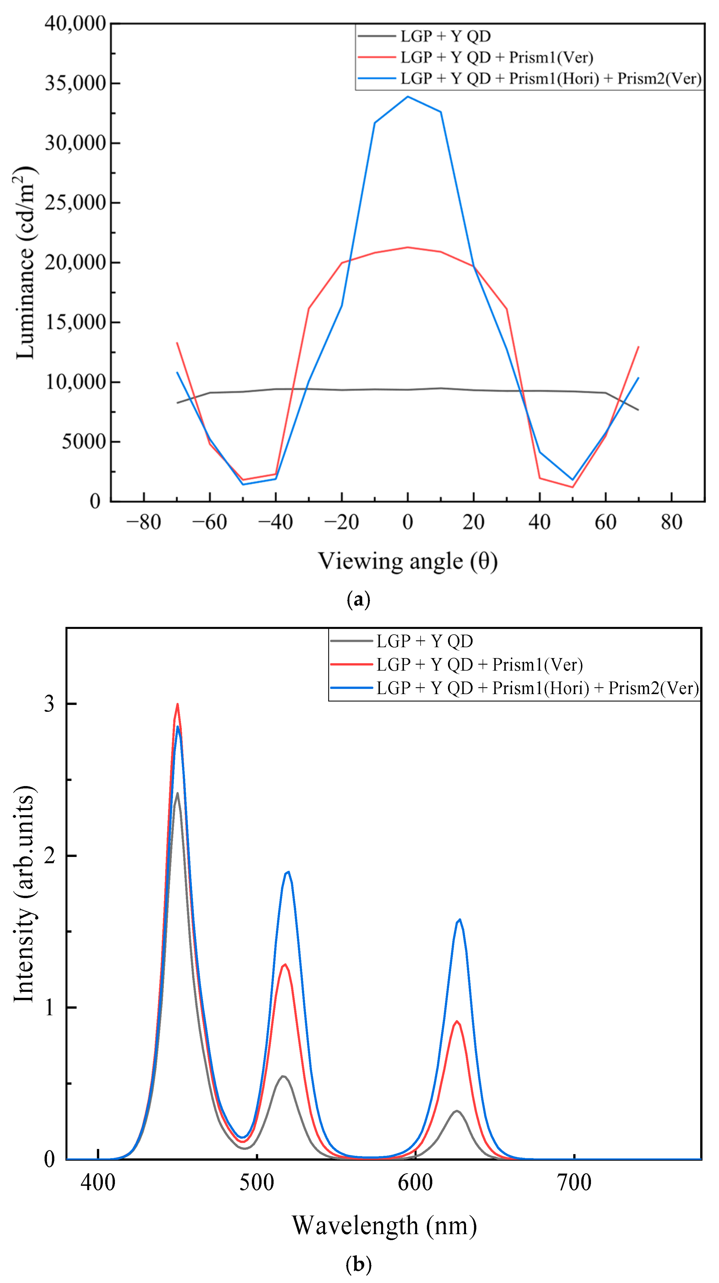
Figure 4 compares the luminance and spectra obtained with the prism grooves of the uppermost film oriented vertically, in contrast to the horizontal configuration in Figure 3. The normal luminance exhibited a similar increasing trend to that in the horizontal case. However, unlike in Figure 3, which shows that an anomalous peak appeared only at around 50° with two stacked prism films, Figure 4a shows a gradual luminance increase from approximately 50° in both single- and double-film configurations. This behavior is also attributed to the side-lobe phenomenon. When the prism grooves were aligned vertically, light rays propagating toward large viewing angles could pass through without obstruction from adjacent grooves, thereby forming side lobes, as shown in Figure 4a. The spectra in Figure 4b further demonstrate the role of the prism films in enhancing the color conversion efficiency of the QD film, consistent with the results shown in Figure 3b.
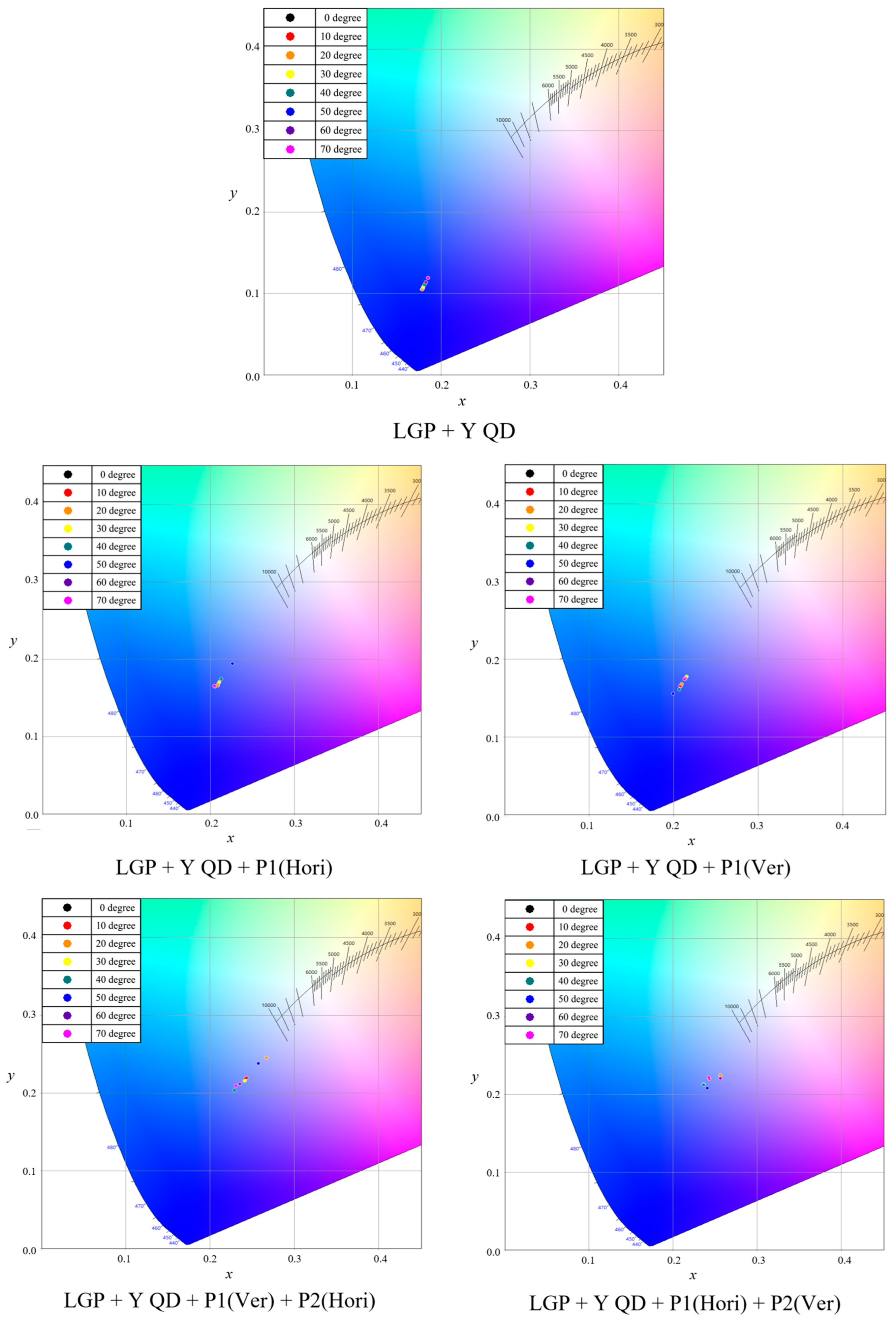
Figure 5 compares the chromaticity coordinates across viewing angles for the configurations in Figure 3 and Figure 4. When only the yellow QD film was applied, more pronounced color conversion occurred at wider viewing angles, resulting in a systematic shift toward the white region on the chromaticity diagram. This effect was primarily attributed to the longer optical path length of the blue excitation light traveling through the QD film at high viewing angles. However, the conversion remained insufficient, and the chromaticity coordinates stayed in the blue region. In display applications, maintaining color uniformity across viewing angles is critical; therefore, such a color distribution is not desirable for high-quality performance.
When prism films were applied, regardless of whether the prism groove orientation was vertical or horizontal, enhanced color conversion was observed, accompanied by a shift in chromaticity coordinates toward the white region. In particular, stacking two prism films produced additional color conversion, moving the coordinates even closer to the white point. However, significant color non-uniformity was also observed, as evidenced by substantial shifts in chromaticity coordinates with viewing angle, consistent with the luminance and spectral profiles. To minimize color deviation across viewing angles, it is essential to achieve a uniform light distribution by controlling light diffusion and implementing appropriate optical path modifications. Therefore, we further investigated the optical characteristics of the system by varying the position, transmittance, and haze of additionally applied diffusion films.
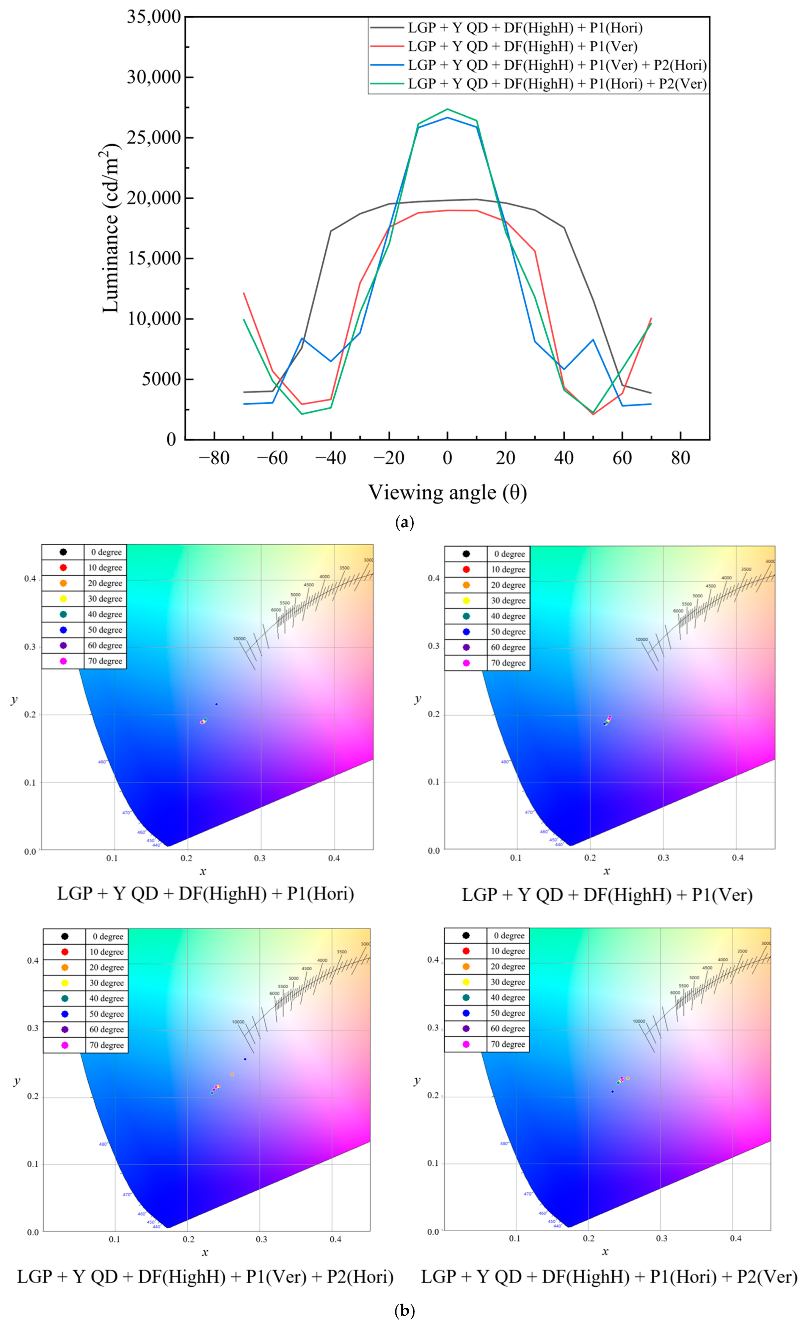
Figure 6a compares the angular luminance distributions when a HighH-type DF was inserted between the QD film and either one or two prism films, as in Figure 3 and Figure 4. In both cases, the luminance profiles closely resembled those without the DF, and the side-lobe phenomenon persisted. The overall luminance decreased by approximately 8% with one prism film and by about 19% with two stacked prism films, due to the reduced transmittance of the DF. The spectral distribution exhibited a similar decreasing trend. Figure 6b shows the chromaticity coordinates across viewing angles for the configurations in Figure 6a. Although a slight reduction in color dispersion was observed, substantial deviation remained, and abrupt chromaticity shifts at specific viewing angles were not eliminated. This limitation is attributed to the DF’s insufficient ability—despite its placement within the optical cavity—to suppress the side-lobe phenomenon inherent to the geometric structure of prism films. Therefore, optimizing the DF position is necessary to better exploit its scattering properties and achieve a more uniform light distribution. Supplementary Figure S4 provides the emission spectra of the four backlight configurations in Figure 6a as a function of viewing angle.
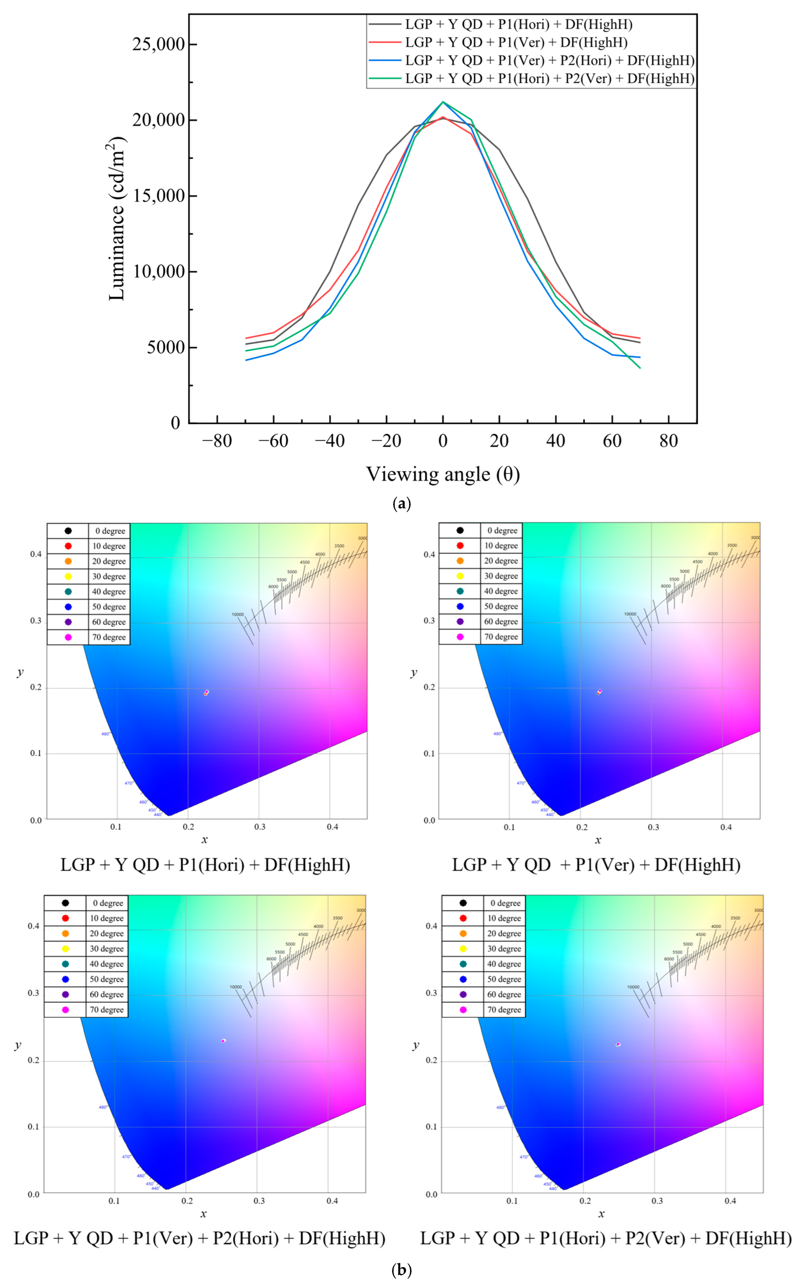
Figure 7a presents the angular luminance distributions for each configuration with a HighH-type DF applied as the topmost layer above the prism films. In all cases, the side-lobe phenomenon was completely suppressed, and the angular luminance profiles showed no abrupt changes, resulting in improved uniformity. When a single prism film was placed below the DF, the on-axis luminance was comparable to that obtained when the prism film was positioned above the DF. However, when two prism films were placed below the DF, the on-axis luminance was lower than that of the configuration with the prism films above. This reduction is attributed to the scattering property of the DF, which redirected the collimated light away from the normal direction. With a single prism film, the DF-induced scattering had little impact because the viewing-angle distribution was relatively broad. In contrast, with two stacked prism films, the light was strongly collimated, and the DF substantially dispersed this light, leading to a reduction in on-axis luminance. As a result, the angular distribution became more uniform, resembling that of the single-film configuration.
As illustrated in Figure 7b, all configurations exhibited minimal color deviation, with chromaticity coordinates remaining stable over the full viewing range. The configuration with two stacked prism films demonstrated the highest color uniformity, likely due to the enhanced scattering effect. These results indicate that introducing a diffusing layer above the QD backlight was effective in suppressing color dispersion arising from variations in the optical path length within the QD film. Supplementary Figure S5 presents the emission spectra of the four backlight configurations in Figure 7a as a function of viewing angle.
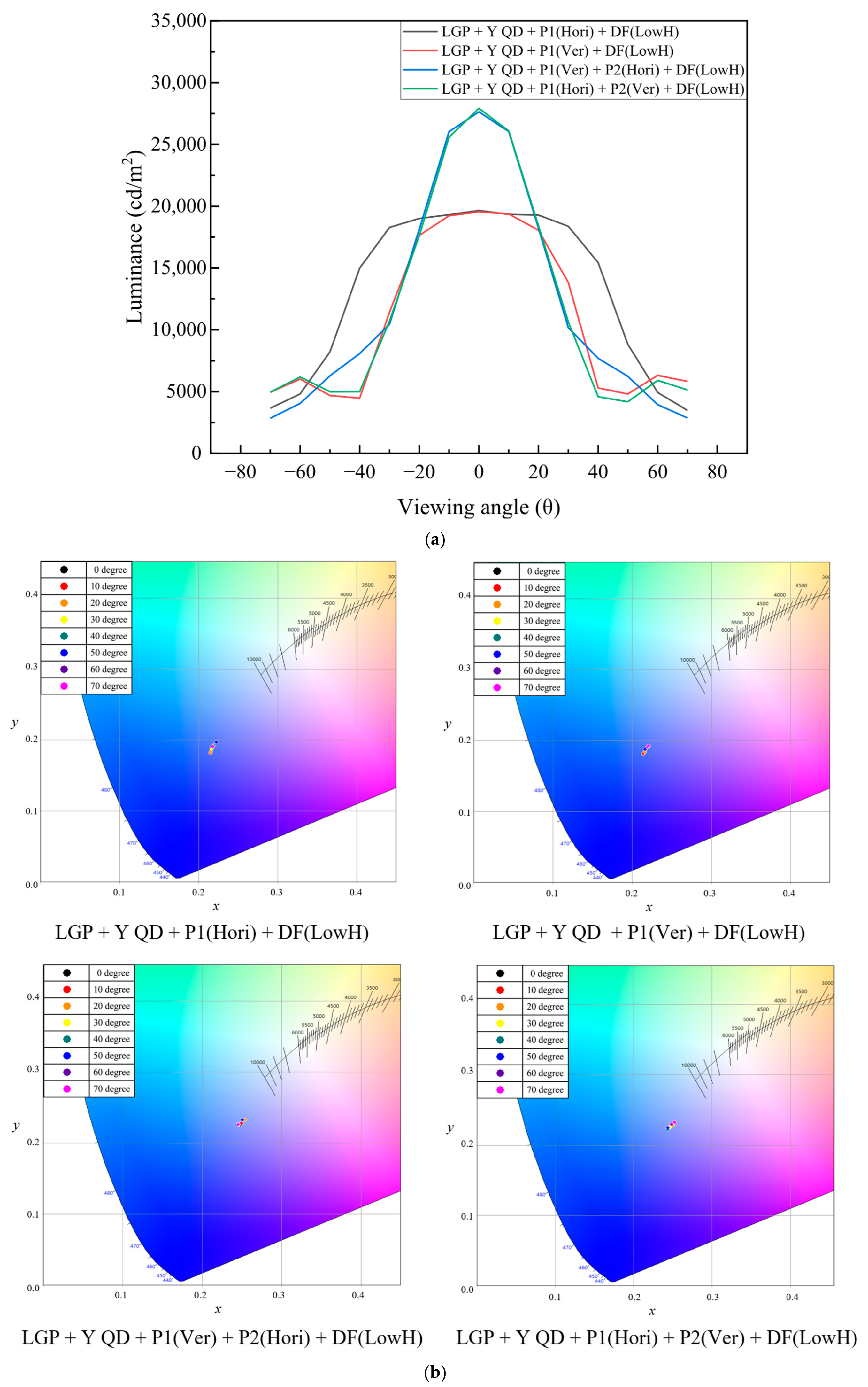
To investigate the effect of the DF haze value on angular luminance distribution and chromaticity variation, a comparative analysis was conducted using a LowH-type DF applied as the topmost layer above the prism film(s). As shown in Figure 8a, the overall luminance distributions were qualitatively similar to those in Figure 6a. The profiles exhibited strong collimation and noticeably reduced side-lobe characteristics. The on-axis luminance values were comparable to those in Figure 6a, where the HighH-type DF was placed beneath the prism film(s). These results are primarily attributed to the low haze and high parallel transmittance of the LowH-type DF, as listed in Table 1. Figure 8b presents the chromaticity coordinates across viewing angles for the configurations in Figure 8a. The angular color uniformity improved compared with Figure 6b but remained inferior to that in Figure 7b. Supplementary Figure S6 provides the emission spectra of the four backlight configurations in Figure 8a as a function of viewing angle.
To further validate the color-dispersion reduction observed in this study, we compared our proposed configuration with the HighH-type DF used with a commercial 65-inch QD mini-LED TV. As illustrated in Figure S3, the commercial product consisted of a blue mini-LED array, a diffusion sheet, a QD film, and a composite sheet. Figure S7a shows the angular luminance distribution of the commercial backlight, which was similar to that in Figure 7a. However, the chromaticity variation shown in Figure S7b was noticeably greater than that in Figure 7b. Consequently, the proposed film stack demonstrated improved color uniformity over the entire viewing-angle range compared with the commercial configuration. While the color coordinates of the commercial system varied substantially with viewing angle, the proposed stack maintained a stable color point, indicating superior angular color uniformity. Table 3 summarizes the comparison of color coordinates as a function of viewing angle, highlighting the superior performance of the LGP + Y QD + P1(Hori) + P2(Ver) + DF(HighH) configuration. This finding is further supported by the color-difference data relative to the normal incidence for five optical film configurations, as shown in Figure 9. The color difference observed for the LGP + Y QD + P1(Hori) + P2(Ver) + DF(HighH) configuration was smaller than those reported in previous simulation results [27] and experimental results [29]. This improvement is also evident from the reduced color dispersion on the chromaticity diagram reported in Ref. [29]. Previous studies on QD-LED and QD-based micro-LED devices showed that the appropriate incorporation of diffusing structures was important in improving angular color shift [41,42]. The negligible angular color shift reported in Ref. [43] should be evaluated from a different perspective, as the small color shift in that study was mainly attributed to the optimization of the microcavity structure in addition to the narrow spectral half-widths of the emission.
The color coordinates achieved from this study are located in the bluish area on the chromaticity diagram and are lower than the usual values appropriate for LCD TV backlights. We consider the relatively low coordinates and their adjustment to be a technical matter that can be addressed by further optimization, such as tuning the film thickness and/or the QD concentration. The primary focus of this study is the inherent color dispersion introduced by QD films in backlights—a problem that has not been thoroughly addressed in previous research. The optical solution proposed here can be applied to any QD-based backlight employing a remote-type QD configuration, such as a thin-film design. However, variations in the thickness or concentration of the QD film could significantly influence the optimization of the optical structure, and may require additional optimization of the haze characteristics of the diffusion film placed on top of the backlight. Such variations may also affect the degree of color dispersion.
The CdSe-based QDs include toxic elements, which may be a problem from an environmental point of view. The adoption of Cd-free QDs, such as InP-based QDs [46], may be a solution to this issue. However, the fundamental optical function of the QD film in the backlight remains the same; therefore, all results and suggestions presented in this study are equally applicable to InP-based QD systems.
Overall, these findings confirm that, in QD-based white backlight systems, angular luminance, spectral characteristics, and color dispersion are critically influenced by the number and orientation of prism films, the placement of the DF, and its haze property. In particular, optical configurations incorporating a high-haze DF effectively suppressed color shift over the full viewing range, ensuring consistent color performance. These results demonstrate the practical potential of such configurations for improving angular color uniformity in QD backlight applications.

4. Conclusions

In this study, we examined a white backlight system incorporating a yellow quantum dot (QD) film over a blue LED backlight and explored optical film combinations to reduce angular color dispersion—a persistent challenge in QD-based backlights. The use of prism films created vertical optical cavities with the bottom reflector, promoting reciprocal light propagation that enhanced luminance and increased the excitation efficiency of the QD film, thereby improving the color conversion efficiency. The side-lobe phenomenon, inherent to prism films, was analyzed, and its characteristics were found to vary with the groove orientation of the topmost prism film, underscoring the critical influence of this layer on angular light distribution. To address this issue, diffusion films (DFs) were introduced at various positions within the stack. Notably, placing the DF above the prism films effectively suppressed side lobes, yielding both uniform luminance and stable chromaticity coordinates across a wide viewing-angle range. In particular, substantial light scattering from a high-haze DF proved most effective in reducing the color dispersion. These findings offer a practical strategy for mitigating angular color dispersion in remote QD backlight structures and can significantly contribute to enhancing the optical performance and color uniformity of next-generation QD-based display systems.

Supplementary Materials

The following supporting information can be downloaded at https://www.mdpi.com/article/10.3390/photonics12090864/s1: Figure S1: the blue backlight; Figure S2: two diffuser films; Figure S3: QD backlight in a commercial LCD TV; Figure S4: the emission spectra for Figure 6a; Figure S5: the emission spectra for Figure 7a; Figure S6: the emission spectra for Figure 8a; Figure S7: characteristics of the commercial QD backlight.

Author Contributions

Conceptualization, D.-H.K. and J.-H.K.; methodology, D.-H.K. and J.-H.K.; software, D.-H.K., J.-Y.K., M.-H.S. and J.-S.Y.; validation, D.-H.K. and J.-H.K.; formal analysis, D.-H.K., J.-Y.K., M.-H.S. and J.-S.Y.; investigation, D.-H.K., J.-Y.K., M.-H.S. and J.-S.Y.; resources, J.-H.K.; data curation, D.-H.K., J.-Y.K., M.-H.S. and J.-S.Y.; writing—original draft preparation, D.-H.K. and J.-H.K.; writing—review and editing, D.-H.K., J.-Y.K., M.-H.S., J.-S.Y. and J.-H.K.; visualization, D.-H.K.; supervision, J.-H.K.; project administration, J.-H.K.; funding acquisition, J.-H.K. All authors have read and agreed to the published version of the manuscript.

Funding

This work was supported by the National Research Foundation of Korea (NRF) grant funded by the Korea government (MIST) (No. RS-2023-00219703) and by the Ministry of Trade, Industry and Energy (MOTIE), Korea Institute for Advancement of Technology (KIAT), through the program of Smart Specialized Infrastructure Construction (no. P0013743).

Acknowledgments

The authors thank Inno QD Co., Ltd. for providing quantum dot films and offering various insights for this research.

Conflicts of Interest

The authors declare no conflict of interest.

References

  1. Kybayashi, S.; Mikoshiba, S.; Lim, S. (Eds.) LCD Backlights; Wiley: Hoboken, NJ, USA, 2009. [Google Scholar]
  2. Schubert, E.F.; Kim, J.K.; Luo, H.; Xi, J.-Q. Solid-state lighting—A benevolent technology. Rep. Prog. Phys. 2006, 69, 3069. [Google Scholar] [CrossRef]
  3. Pust, P.; Schmidt, P.J.; Schnick, W. A revolution in lighting. Nat. Mater. 2015, 14, 454. [Google Scholar] [CrossRef]
  4. Lin, C.C.; Liu, R.-S. Advances in phosphors for light-emitting diodes. J. Phys. Chem. Lett. 2011, 2, 1268. [Google Scholar] [CrossRef]
  5. McKittrick, J.; Shea-Rohwer, L.E. Down conversion materials for solid-state lighting. J. Am. Ceram. Soc. 2014, 97, 1327. [Google Scholar] [CrossRef]
  6. Choi, H.-W.; Choi, M.H.; Ko, J.-H. Effect of Temperature on the Luminous Properties of White-light-emitting Diodes with Red and Green Phosphors. New Phys. Sae Mulli 2013, 63, 1149. [Google Scholar] [CrossRef]
  7. Erdem, T.; Demir, H.V. Color science of nanocrystal quantum dots for lighting and displays. Nanophotonics 2013, 2, 57. [Google Scholar] [CrossRef]
  8. Bae, W.K.; Lim, J.; Lee, D.; Park, M.; Lee, H.; Kwak, J.; Char, K.; Lee, C.; Lee, S. R/G/B/natural white light thin colloidal quantum dot-based light-emitting devices. Adv. Mater. 2014, 26, 6387. [Google Scholar] [CrossRef] [PubMed]
  9. Lim, S.J.; Zahid, M.U.; Le, P.; Ma, L.; Entenberg, D.; Harney, A.S.; Condeelis, J.; Smith, A.M. Brightness-equalized quantum dots. Nat. Commun. 2015, 6, 8210. [Google Scholar] [CrossRef]
  10. Lim, J.; Park, Y.S.; Wu, K.; Yun, H.J.; Klimov, V.I. Droop-free colloidal quantum dot light-emitting diodes. Nano Lett. 2018, 18, 6645. [Google Scholar] [CrossRef]
  11. Denault, K.A.; Mikhailovsky, A.A.; Brinkley, S.; DenBaars, S.P.; Seshadri, R. Improving color rendition in solid state white lighting through the use of quantum dots. J. Mater. Chem. C 2013, 1, 1461. [Google Scholar] [CrossRef]
  12. Chung, S.-R.; Chen, S.-S.; Wang, K.-W.; Siao, C.-B. Promotion of solid-state lighting for ZnCdSe quantum dot modified-YAG-based white light-emitting diodes. RSC Adv. 2016, 6, 51989. [Google Scholar] [CrossRef]
  13. Li, C.; Murase, N. Synthesis of Highly Luminescent Glasses Incorporating CdTe Nanocrystals through Sol-Gel Processing. Langmuir 2004, 20, 1. [Google Scholar] [CrossRef]
  14. Bullen, C.; Mulvaney, P.; Sada, C.; Ferrari, M.; Chiasera, A.; Martucci, A. Incorporation of a highly luminescent semiconductor quantum dot in ZrO2–SiO2 hybrid sol–gel glass film. J. Mater. Chem. 2004, 14, 1112. [Google Scholar] [CrossRef]
  15. Tetsuya, H.; Ebina, T.; Mizukami, F. Highly luminescent flexible quantum dot-clay films. Adv. Mater. 2008, 20, 3039. [Google Scholar] [CrossRef]
  16. Mutlugun, E.; Hernandez-Martinez, P.L.; Eroglu, C.; Coskun, Y.; Erdem, T.; Sharma, V.K.; Unal, E.; Panda, S.K.; Hicky, S.G.; Gaponik, N.; et al. Large-Area (over 50 cm × 50 cm) Freestanding Films of Colloidal InP/ZnS Quantum Dots. Nano Lett. 2012, 12, 3986. [Google Scholar] [CrossRef]
  17. Kim, J.-H.; Yang, H. White lighting device from composite films embedded with hydrophilic Cu(In, Ga)S2/ZnS and hydrophobic InP/ZnS quantum dots. Nanotechnology 2014, 25, 225601. [Google Scholar] [CrossRef]
  18. Lien, J.-Y.; Chen, C.-J.; Chiang, R.-K.; Wang, S.-L. High color-rendering warm-white lamps using quantum-dot color conversion films. Opt. Express 2016, 24, A1021. [Google Scholar] [CrossRef] [PubMed]
  19. Jang, E.; Jun, S.; Jang, H.; Lim, J.; Kim, B.; Kim, Y. White-light-emitting diodes with quantum dot color converters for display backlights. Adv. Mater. 2010, 22, 3076. [Google Scholar] [CrossRef] [PubMed]
  20. Jun, S.; Lee, J.; Jang, E. Highly luminescent and photostable quantum dot–silica monolith and its application to light-emitting diodes. ACS Nano 2013, 7, 1472. [Google Scholar] [CrossRef]
  21. Altintas, Y.; Genc, S.; Talpur, M.Y.; Mutlugun, E. CdSe/ZnS quantum dot films for high performance flexible lighting and display applications. Nanotechnology 2016, 27, 295604. [Google Scholar] [CrossRef] [PubMed]
  22. Chen, H.-W.; Zhu, R.-D.; He, J.; Duan, W.; Hu, W.; Lu, Y.-Q.; Li, M.-C.; Lee, S.-L.; Dong, Y.-J.; Wu, S.-T. Going beyond the limit of an LCD’s color gamut. Light Sci. Appl. 2017, 6, e17043. [Google Scholar] [CrossRef]
  23. Abe, S.; Joos, J.J.; Martin, L.I.D.; Hens, Z.; Smet, P.F. Hybrid remote quantum dot/powder phosphor designs for display backlights. Light Sci. Appl. 2017, 6, e16271. [Google Scholar] [CrossRef]
  24. Chen, E.; Xie, H.; Huang, J.; Miu, H.; Shao, G.; Li, Y.; Guo, T.; Xu, S.; Ye, Y. Flexible/curved backlight module with quantum-dots microstructure array for liquid crystal displays. Opt. Express 2018, 26, 3466. [Google Scholar] [CrossRef]
  25. Yang, X.; Lan, X.-Y.; Liu, Y.-S.; Yang, H.-Y.; Li, Y.; Zheng, S.-W. Highly Stable White Light-Emitting Diodes Based on Quantum-Dots Dispersed Into the Backlight Lens for Display Backlight. IEEE Photonics J. 2019, 11, 8200707. [Google Scholar] [CrossRef]
  26. Kim, S.J.; Jang, H.W.; Lee, J.-G.; Ko, J.-H.; Ko, Y.W.; Kim, Y. Substantial Improvement of Color-Rendering Properties of Conventional White LEDs Using Remote-Type Red Quantum-Dot Caps. New Phys. Sae Mulli 2019, 69, 861. [Google Scholar] [CrossRef]
  27. Lee, J.-G.; Ko, J.-H. Simulation Study on the Improvement of the Luminance and the Color Uniformities of Integrated Quantum-Dot Backlights for LCD Applications. J. Korean Phys. Soc. 2020, 77, 264. [Google Scholar] [CrossRef]
  28. Halder, S.; Shin, Y.; Zhou, Z.; Zhang, X.; Hu, L.; Yang, D.-K. Aligned polymer dispersed liquid crystal film for light enhancement of quantum dot backlight. Opt. Express 2021, 29, 43241. [Google Scholar] [CrossRef]
  29. Lee, G.J.; Lee, J.-G.; Kim, Y.; Park, T.; Ko, Y.W.; Ko, J.-H. The effect of the reflective property of a reflection film on the performance of backlight units with quantum-dot films for LCD applications. J. Inf. Disp. 2021, 22, 55. [Google Scholar] [CrossRef]
  30. Chen, Y.L.; Ye, Z.T.; Lai, W.; Chiu, C.C.; Lin, K.W.; Han, P. Application of mini-LEDs with microlens arrays and quantum dot film as extra-thin, large-area, and high-luminance backlight. Nanomaterials 2022, 12, 1032. [Google Scholar] [CrossRef]
  31. Huang, B.; Chen, E.; Sun, L.; Guo, T. Quantum-dot color conversion film patterned by screen printing and overprinting process for display backlights. Opt. Laser Technol. 2022, 145, 107486. [Google Scholar] [CrossRef]
  32. Lee, T.-Y.; Huang, W.-T.; Chen, J.-H.; Liu, W.-B.; Chang, S.-W.; Chen, F.-C.; Kuo, H.-C. Optimized design with artificial intelligence quantum dot white mini LED backlight module development. Crystals 2023, 13, 1411. [Google Scholar] [CrossRef]
  33. Luo, Z.; Chen, Y.; Wu, S.-T. Wide color gamut LCD with a quantum dot backlight. Opt. Express 2023, 21, 26269. [Google Scholar] [CrossRef]
  34. Zhang, W.; Chen, Y.; Cai, J.; Deng, L.; Xu, S.; Ye, Y.; Yan, Q.; Guo, T.; Chen, E. Uniformity improvement of a mini-LED backlight by a quantum-dot color conversion film with nonuniform thickness. Opt. Lett. 2023, 48, 5643. [Google Scholar] [CrossRef]
  35. Lee, S.-M.; Choo, H.-H.; Jang, J.-H.; Kwak, M.-J.; Baek, E.; Kim, S.; Ko, J.-H. Correlation between the gain factor of a reflective polarizer and the optical structure of quantum dot-based backlights for LCD applications. J. Korean Phys. Soc. 2024, 85, 915. [Google Scholar] [CrossRef]
  36. Chen, J.; Zhao, Q.; Yu, B.; Lemmer, U. A Review on Quantum Dot-Based Color Conversion Layers for Mini/Micro-LED Displays: Packaging, Light Management, and Pixelation. Adv. Opt. Mater. 2024, 12, 2300873. [Google Scholar] [CrossRef]
  37. Xu, B.; Zhou, J.; Zhang, C.; Chang, Y.; Deng, Z. Research Progress on Quantum Dot-Embedded Polymer Films and Plates for LCD Backlight Display. Polymers 2025, 17, 233. [Google Scholar] [CrossRef]
  38. Baek, E.; Kim, B.; Kim, S.; Song, J.; Yoo, J.; Park, S.M.; Lee, J.-M.; Ko, J.-H. Color Rendering Index over 95 Achieved by Using Light Recycling Process Based on Hybrid Remote-Type Red Quantum-Dot Components Applied to Conventional LED Lighting Devices. Nanomaterials 2023, 13, 2560. [Google Scholar] [CrossRef]
  39. Lee, G.; Lee, H.; Cho, J.; Choi, I.; Park, S.M.; Ko, J.-H. Study on High-Efficiency White Light-Emitting Diodes Using a Remote Phosphor with Cadmium-Free Quantum Dots. New Phys. Sae Mulli 2023, 73, 703. [Google Scholar] [CrossRef]
  40. Yoo, J.; Baek, E.; Kim, S.; Lee, H.; Park, S.M.; Ko, J.-H. Tunable viewing angle characteristics of QD-enhanced LED lighting through combinations of holographic diffuser and prism film. J. Korean Phys. Soc. 2025, 86, 1101. [Google Scholar] [CrossRef]
  41. Shi, L.; Chen, S. Over 32.5% Efficient Top-Emitting Quantum-Dot LEDs with Angular-Independent Emission. ACS Appl. Mater. Interfaces 2022, 14, 30039. [Google Scholar] [CrossRef] [PubMed]
  42. Dai, B.-L.; Ji, J.-W.; Wu, B.-H.; Chen, K.-A.; Kuroda, H.; Kou, H.-C.; Akada, T.; Li, C.-Y. Investigation and comparison of the influence of modified DBR and yellow color filters for quantum dot color conversion-based micro LED applications. Heliyon 2024, 10, e35492. [Google Scholar] [CrossRef] [PubMed]
  43. Li, M.; Li, R.; Wu, L.; Lin, X.; Xia, X.; Ao, Z.; Sun, X.; Chen, X.; Chen, S. Ultrabright and stable top-emitting quantum-dot light-emitting diodes with negligible angular color shift. Nat. Commun. 2024, 15, 5161. [Google Scholar] [CrossRef] [PubMed]
  44. Lee, W.G.; Jeong, J.H.; Lee, J.-Y.; Nahm, K.-B.; Ko, J.-H.; Kim, J.H. Light output characteristics of rounded prism films in the backlight unit for liquid crystal display. J. Inf. Disp. 2006, 7, 1. [Google Scholar] [CrossRef]
  45. Watson, P.; Boyd, G.T. Mobile Displays; Bhowmik, A.K., Li, Z., Bos, P.J., Eds.; Wiley: Hoboken, NJ, USA, 2008. [Google Scholar]
  46. Won, Y.-H.; Cho, O.; Kim, T.; Chung, D.-Y.; Kim, T.; Chung, H.; Jang, H.; Lee, J.; Kim, D.; Jang, E. Highly efficient and stable InP/ZnSe/ZnS quantum dot light-emitting diodes. Nature 2019, 575, 634. [Google Scholar] [CrossRef] [PubMed]
Figure 1. Layer structures for each combination of optical films.
Photonics 12 00864 g001
Figure 2. (a) The angular distribution of luminance for the blue backlight without and with the yellow QD film, and (b) the emitting spectra of backlight without and with the yellow QD film.
Photonics 12 00864 g002
Figure 3. (a) Luminance as a function of viewing angle for a blue backlight with yellow QD and prism films (single horizontal prism vs. dual prism in vertical–horizontal arrangement), and (b) the emission spectra of the three types of backlights as a function of viewing angle, as shown in Figure 2a.
Photonics 12 00864 g003
Figure 4. (a) Luminance as a function of viewing angle for a blue backlight with yellow QD film and prism films (single vertical prism vs. dual prism in horizontal–vertical arrangement), and (b) the emission spectra of the three types of backlights as a function of viewing angle, as shown in Figure 3a.
Photonics 12 00864 g004
Figure 5. Color coordinate changes according to viewing angle for a blue backlight with yellow QD film, when a prism film is applied vertically and horizontally, and when two prism films are stacked in vertical–horizontal and horizontal–vertical orders.
Photonics 12 00864 g005
Figure 6. (a) Angular luminance distributions and (b) color coordinate changes as a function of viewing angle for configurations in which a HighH-type DF is placed between the yellow QD film and the prism films, with one or two prisms stacked.
Photonics 12 00864 g006
Figure 7. (a) Angular luminance distribution and (b) color coordinate variation as a function of viewing angle for configurations in which a HighH-type DF is placed above one or two stacked prism films.
Photonics 12 00864 g007
Figure 8. (a) Angular luminance distribution and (b) color coordinate variation as a function of viewing angle for configurations in which a LowH-type DF is placed above one or two stacked prism films.
Photonics 12 00864 g008
Figure 9. Color difference as a function of viewing angle, relative to the value measured along the normal direction, for five optical film configurations.
Photonics 12 00864 g009
Table 1. Haze meter measurement values of the used diffusion film.
HazeTotal
Transmittance
Parallel
Transmittance
Diffuse
Transmittance
DF(HighH)97.0795.552.892.75
DF(LowH)67.9691.3829.2862.10
Table 2. On-axis luminance and color coordinate properties for each optical film combination.
Combination of Optical FilmsLuminance (cd/m2)xy
LGP23800.15320.0232
LGP + YQD93570.17870.1045
LGP + YQD + P1(Hori)20,5000.20760.1674
LGP + YQD + P1(Ver)21,2800.20810.1647
LGP + YQD + P1(Ver) + P2(Hori)33,3100.24220.2176
LGP + YQD + P1(Hori) + P2(Ver)33,9000.24330.2199
LGP + YQD + DF(HighH) + P1(Hori)19,8200.22160.189
LGP + YQD + DF(HighH) + P1(Ver)18,9900.22120.1867
LGP + YQD + DF(HighH) + P1(Ver) + P2(Hori)27,2400.24260.2151
LGP + YQD + DF(HighH) + P1(Hori) + P2(Ver)27,3700.24650.2243
LGP + YQD + P1(Hori) + DF(HighH)20,1200.22470.1907
LGP + YQD + P1(Hori) + DF(LowH)19,6600.21490.181
LGP + YQD + P1(Ver) + DF(HighH)20,2200.22550.1915
LGP + YQD + P1(Ver) + DF(LowH)19,5600.21450.1808
LGP + YQD + P1(Ver) + P2(Hori) + DF(HighH)21,2100.25440.2319
LGP + YQD + P1(Ver) + P2(Hori) + DF(LowH)27,6400.24820.2257
LGP + YQD + P1(Hori) + P2(Ver) + DF(HighH)16,0800.24980.2256
LGP + YQD + P1(Hori) + P2(Ver) + DF(LowH)27,9300.24770.2262
Table 3. The color differences at 10°, 30°, 50°, and 70° relative to that measured along the normal direction.
Combination of Optical FilmsReference (0°)AngleΔxΔyΔxy
LGP + Y QD + P1(Hori) + P2(Ver)(0.2433, 0.2199)10°0.00010.00010.0001
30°−0.0066−0.00740.0099
50°−0.0023−0.01230.0125
70°−0.00050.00120.0013
LGP + Y QD + DF(HighH) + P1(Ver) + P2(Hori)(0.2426, 0.2151)10°0.00090.00150.0017
30°−0.00030.00070.0008
50°0.03720.04220.0563
70°−0.00280.00070.0029
LGP + Y QD + P1(Hori) + P2(Ver) + DF(HighH)(0.2498, 0.2256)10°−0.0002−0.00010.0002
30°−0.0016−0.00120.002
50°−0.00040.00040.0006
70°−0.00060.00070.0009
LGP + Y QD + P1(Ver) + P2(Hori) + DF(LowH)(0.2482, 0.2257)10°0.00150.00190.0024
30°−0.00200.002
50°0.00270.00650.007
70°−0.00260.00010.0026
65-Inch QD-Mini LED TV(0.2989, 0.2619)10°−0.0002−0.00010.0002
30°0.00330.00370.005
50°0.00260.00280.0038
70°0.00440.00550.007
Disclaimer/Publisher’s Note: The statements, opinions and data contained in all publications are solely those of the individual author(s) and contributor(s) and not of MDPI and/or the editor(s). MDPI and/or the editor(s) disclaim responsibility for any injury to people or property resulting from any ideas, methods, instructions or products referred to in the content.