Article

A Checkerboard Corner Detection Method for Infrared Thermal Camera Calibration Based on Physics-Informed Neural Network

by
Zhen Zuo
,
Zhuoyuan Wu
,
Junyu Wei
*,
Peng Wu
,
Siyang Huang
and
Zhangjunjie Cheng
College of Intelligence Science and Technology, National University of Defense Technology, Changsha 410073, China
*
Author to whom correspondence should be addressed.
Photonics 2025, 12(9), 847; https://doi.org/10.3390/photonics12090847
Submission received: 3 July 2025 / Revised: 20 August 2025 / Accepted: 22 August 2025 / Published: 25 August 2025
(This article belongs to the Special Issue Optical Imaging and Measurements: 2nd Edition)

Abstract

Control point detection is a critical initial step in camera calibration. For checkerboard corner points, detection is based on inferences about local gradients in the image. Infrared (IR) imaging, however, poses challenges due to its low resolution and low signal-to-noise ratio, hindering the identification of clear local features. This study proposes a physics-informed neural network (PINN) based on the YOLO target detection model to detect checkerboard corner points in infrared images, aiming to enhance the calibration accuracy of infrared thermal cameras. This method first optimizes the YOLO model used for corner detection based on the idea of enhancing image gradient information extraction and then incorporates camera physical information into the training process so that the model can learn the intrinsic constraints between corner coordinates. Camera physical information is applied to the loss calculation process during training, avoiding the impact of label errors on the model and further improving detection accuracy. Compared with the baselines, the proposed method reduces the root mean square error (RMSE) by at least 30% on average across five test sets, indicating that the PINN-based corner detection method can effectively handle low-quality infrared images and achieve more accurate camera calibration.

Graphical Abstract

1. Introduction

Infrared thermography is a method of imaging using infrared radiation that converts invisible thermal radiation emitted by an object into a visualized image. This technique is based on the relationship between the temperature of an object and the energy of the infrared radiation it emits. All objects emit infrared radiation based on their temperature and emissivity, and infrared thermal cameras are able to capture this radiation and convert it into an electrical signal, which in turn generates an image that reflects the temperature or emissivity distribution on the surface of the object.
Infrared thermal cameras have a wide range of applications as non-contact temperature measurement tools [1,2]. Although infrared thermal imaging cameras are affected by the inherent ambiguity between emissivity and temperature measurements, it is usually possible to determine whether an abnormal situation exists by referring to thermal radiation imaging under normal conditions. In the engineering field, temperature detection can detect equipment failures in time [3] and prevent secondary disasters, such as fires. In the medical field, infrared thermal cameras can be used to detect small temperature changes on the surface of the human body [4,5], providing information to aid diagnosis. In the military field, infrared imaging has been widely used for target detection due to its ability to work around the clock, recognize visible light artifacts, and penetrate smoke [6,7]. Although infrared imaging provides information about the distribution of thermal radiation, this information needs to be matched with a target or area in the physical world to be of practical significance. For example, hand–eye calibration is required for IR cameras and operating equipment in industrial or medical fields [8,9], and, in tasks such as smart driving and unmanned reconnaissance [10,11], IR cameras need to sense the actual physical location of the target. In order to realize the transformation from temperature information to actual objects, i.e., pixel coordinates to world coordinates, geometric calibration of the IR camera is required.
The calibration process for common infrared cameras is similar to the calibration process for general optical cameras. In both cases, a target with a specific geometry is photographed from different angles, feature points are extracted, and then the internal parameters of the camera are solved. The difference is that the calibration targets for IR cameras are more complex and usually based on blackbody simulators or thermocouple systems [12] since the feature points of an IR image consist of temperature differences or emissivity differences on the surface of the object. In addition, infrared cameras tend to struggle to provide higher image resolution compared to visible-light cameras, and infrared images also tend to be noisier. These factors lead to greater challenges in calibrating IR cameras.
Camera calibration is the process of solving camera parameters by the known positions of the corner points in the image [13]. Therefore, corner detection accuracy directly affects calibration accuracy. There are two main factors affecting calibration accuracy [14]. On the one hand, there are errors in the physical dimensions of the calibration target (e.g., checkerboard calibration plate, circular pattern calibration plate, etc.); on the other hand, there are inaccuracies in the positions of the corners detected in the images. The former depend on the manufacturing accuracy of the calibration target, such as the printing accuracy of the calibration patterns, etc., while the latter mainly come from image noise. Usually, the latter have a significantly larger impact on camera calibration accuracy than the former, especially for infrared camera calibration. This is mainly because infrared imaging compared to visible-light imaging has a low resolution, low contrast, low signal-to-noise ratio, and other characteristics, which significantly affect the accurate detection of corners in infrared images. In the case of infrared imaging, many conventional corner detection methods have significantly increased detection errors and even fail to detect corners effectively. Therefore, robust and accurate corner detection methods are the key to IR camera calibration.
For the above problems, the Features from Accelerated Segment Test (FAST) [15] and FAST-Enhanced Repeatability (FAST-ER) [16] represent the research directions of corner detection using machine learning methods. Currently, in the field of machine learning, deep learning methods demonstrate powerful feature mining capabilities. Deep learning algorithms have been used in many applications in the field of calibration image recognition and corner detection in recent years. Du et al. [17] proposed a novel visual tracking method that detects corners based on a relevance-guided attention mechanism to achieve accurate tracking of target objects. Wu et al. [18] proposed a synthetic training data generation method that simulates the real imaging process for training a simple neural network for checkerboard corner detection. Song et al. [19] proposed a method based on fully convolutional networks (FCNs) for corner detection of buildings in aerial images. Dantas et al. [20] implemented checkerboard corner detection by a CNN that segments the checkerboard grid and a CNN that extracts the corner points and evaluated their method on two visible-light datasets, GoPro and uEye. Kang et al. [21] proposed a novel neural network framework to predict the locations of checkerboard corner points by encoding the global context of an image while determining the existence of corner points from a global perspective. Zhu et al. [22] proposed a method called LSCCL (Learning Subpixel Checkerboard Corner Localization), which is based on the EfficientNetv2 framework for subpixel-level corner detection through offset prediction and confidence scoring.
In recent years, the YOLO [23] series of target detection methods based on deep learning have been widely used in many fields, which are able to predict the center position and the width and height of a target directly from the input image by modeling target detection as a regression problem. Some researchers have already employed the YOLO target detection algorithm in the process of camera calibration. Li et al. [24] used a two-layer calibration plate to avoid temperature crosstalk, obtained higher-quality IR calibration images, and used YOLOv4 to detect the calibration plate in the process of binocular calibration of long-wave infrared and visible cameras, but accurate corner detection still relies on accurate edge extraction algorithms. Wang et al. [25] proposed a robust checkerboard corner detection method based on an improved YOLOX deep learning network and the Harris algorithm for calibrating visible-light cameras. The method still works well in large-scale distorted images, but the Harris algorithm is not effective in detecting corners in infrared images. Son et al. [26] used YOLOv8 combined with a deformable convolutional network to implement AprilTag tag detection and correspondence estimation between a projector and camera. This was achieved based on the many different patterns contained in the AprilTag tags, and producing templates with these tags would be very difficult for infrared thermography.
Deep learning algorithms can effectively improve the robustness of corner detection and reduce the missed detection and false alarm rates. However, detected corners usually require further refinement to improve detection accuracy. The Harris algorithm [27] is directly used as an accurate corner detection algorithm in the literature [25]. Shi et al. [28] used a modified Shi–Tomasi [29] subpixel corner detection method for checkerboard corner detection in infrared images. Du et al. [30] extracted dark square edge points by Otsu threshold segmentation as well as gradient computation, then used least squares to fit straight lines and detected the intersection of the lines as corners. Dan et al. [31] proposed a corner detection method for checkerboards based on the EDLines algorithm, where straight lines in the checkerboard grid are detected and intersection points are extracted by the EDLines algorithm. Subpixel corner locations are subsequently obtained using an iterative algorithm based on gray gradient features. Lü et al. [32] used the same algorithm in the section of extracting subpixel corner coordinates, but only for four manually selected corner coordinates, and then computed the homologous matrix of these four corner coordinates with their world coordinates, thus obtaining the subpixel coordinates of all the corners from the world coordinates.
To address the shortcomings of the existing methods, we propose an end-to-end corner detection method based on PINN [33]. On the basis of extracting corner points from the local grayscale features of an image, the method is able to learn the deep information between the coordinates of the corner points from a global perspective by introducing the physical information of the imaging device, which in turn improves the model performance.
The main work and contributions of this paper are as follows:
  • We tested and analyzed the applicability of the YOLO model family for corner detection tasks, and improved the YOLO network structure for checkerboard corner detection tasks. Compared to baseline methods such as MATLAB and OpenCV, our model has improved robustness and accuracy.
  • An unsupervised training method driven by camera physical information is proposed for training the YOLO corner detection model. This method allows the model to learn the intrinsic relationship between corner points, breaks through the bottleneck of conventional training, and effectively improves camera calibration accuracy.
  • A real infrared thermal camera calibration dataset is constructed, and a set of experiments are conducted based on this dataset. The effectiveness of the YOLO model and the unsupervised training method proposed in this paper are verified through these experiments. Ultimately, compared to the baseline approach, our method achieves state-of-the-art performance on our test sets.

2. Materials and Methods

2.1. Materials

The construction of our dataset is based on a calibration board composed of a piece of Dibond® [14] material, as shown in Figure 1a, which is an aluminum composite material capable of near-perfect planarity. The calibration plate has a 9 × 12 checkerboard pattern, with each square measuring 30 mm on each side. The black checkerboard pattern was cured on the surface of the Dibond® material by a high-precision printer capable of providing emissivity different from that of the Dibond® material, which defines clear edges in the infrared image when heated by power. Given the lack of publicly available calibration datasets for IR cameras, we created our own IR image dataset based on this checkerboard calibration board for our experiments. The infrared image acquisition device is the telephoto infrared camera of DJI M300 RTK UAV H20N payload (DJI, Shenzhen, China), as shown in Figure 1b. When capturing images, the calibration board is positioned near the location that provides the clearest image (between 3.5 m and 5.0 m), rotated around the camera’s optical axis, and tilted at varying horizontal and vertical angles (between −45° and 45°). We acquired 1250 infrared images of the calibration board and divided the training set, validation set, and test set according to the ratio of 6:2:2. It is important to note that the test data came from one additional collection from a different site to avoid it being too similar to the training data. The image resolution is 640 × 512. The calibration plates in these images have different shooting distances, tilt angles, and temperatures to ensure a diverse dataset. During the shooting process, the temperature of the calibration plate was controlled between 50 °C and 80 °C, and the equivalent optical magnification of the infrared camera was set to 8×. In addition, the number of images in the training set was expanded from 750 to 3750 after data enhancement (4 data enhancements per image), as shown in Figure 1c. The data enhancement operations include adding Gaussian noise, changing brightness, cutout, rotation, cropping, shifting, and flipping, with each operation being randomized in terms of whether it is employed or not, the order in which it is performed, and the quantization parameters.

2.2. Conventional Methods

In terms of corner detection, most of the traditional checkerboard corner detection algorithms require images with clear edges, sharp contrast, and very low noise, such as the Harris and Shi–Tomasi corner detection algorithms. When these algorithms are used alone for corner detection in infrared images, they are easily interfered with by noise and background, and the threshold selection is difficult, making it almost impossible to detect checkerboard corners effectively. Widely used calibration tools, such as OpenCV [34] and MATLAB toolbox [35], also have unsatisfactory corner detection results in infrared images and are prone to misdetection.
For subpixel computation of corner coordinates, both OpenCV and MATLAB toolboxes use iterative algorithms based on grayscale gradient features [31,32]. The theoretical model of this approach is shown in Figure 2a. The dot product of the gray gradient vector of any point around the corner point and the direction vector from the corner point to the point should be 0, i.e., q i · p i = 0 , because, if the point is inside the square lattice, p i = 0 , and, if it is at the boundary of the square lattice, p i q i . The subpixel coordinates of the corner point can be obtained by establishing four equations based on the four pairs of vectors in Figure 2a and then solving them by the least squares method. However, due to the lower contrast and signal-to-noise ratio of infrared images, the gray gradient near the corner points may be inaccurate, which may lead to inaccurate subpixel calculation results. As shown in Figure 2b, among the four boundary points near the corner point, only the yellow point has a larger deviation in the gradient direction, which still leads to apparent inaccuracy in the calculated subpixel corner position.

2.3. Proposed Method

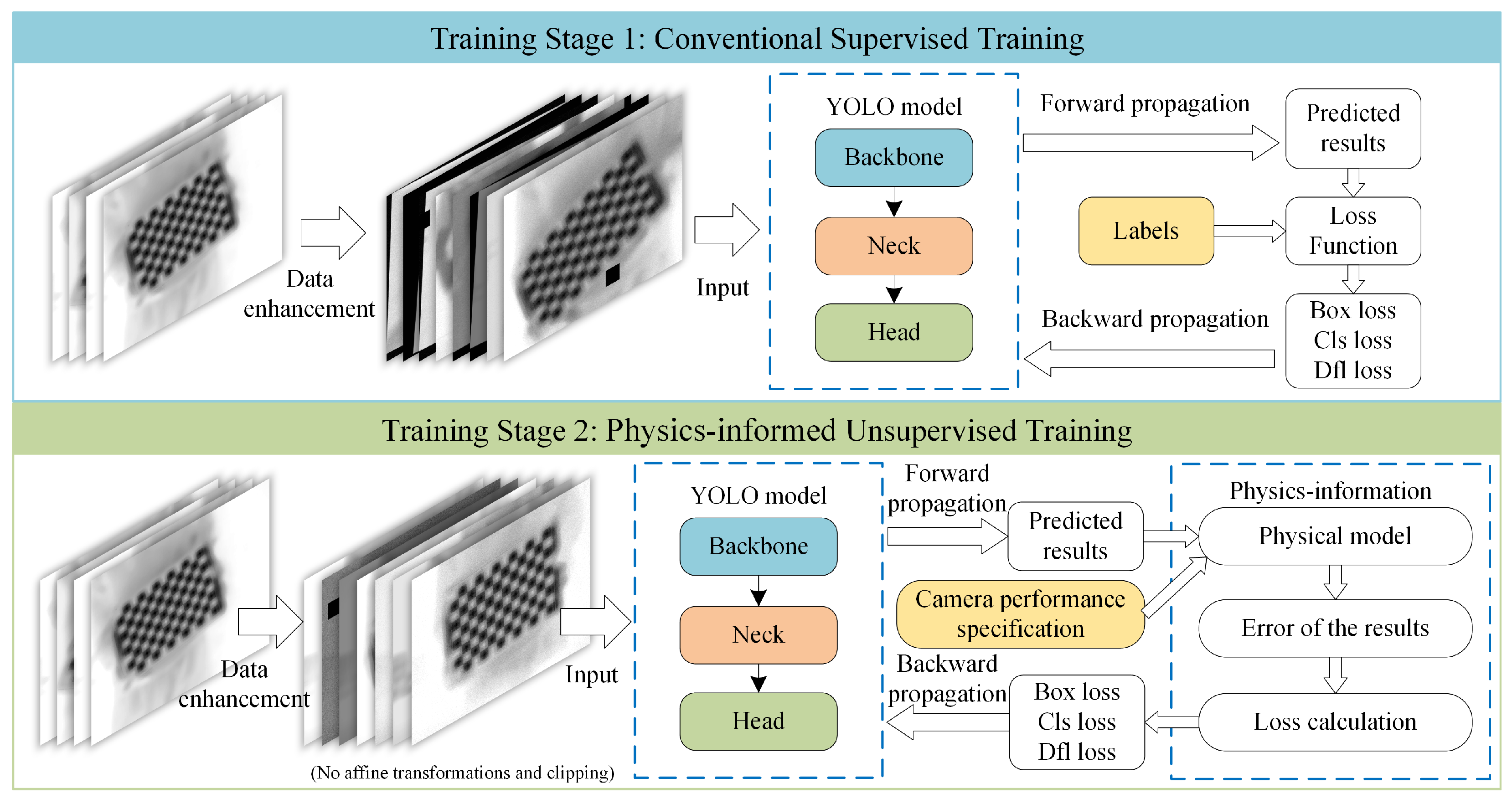
Aiming at the problems of difficult corner detection and inaccurate subpixel corner extraction by conventional methods in infrared camera calibration scenarios, a corner detection method based on the physics-informed YOLO target detection model is proposed. This method detects corner points in the form of a target box, taking the center of the box as the coordinates of the corner, which allows the network to learn the local features of the corner and effectively reduces the cases of missed and false positives. The training of the model is divided into 2 stages. The first stage is regular supervised training based on full data augmentation, which aims to bring the model close to convergence. At this point, the model predicts corner locations that are not precise enough because the labels are handmade and are usually only accurate to 0.5 pixels. In the second training stage, the network model is trained using information provided based on the physical model of the camera. At this point, the data enhancement operations do not include affine transformations and image cropping as these operations result in changes to the physical model of imaging. This process allows the model to learn the physical constraints of the corner points with respect to each other. The overall training process is shown in Figure 3.

2.3.1. Model Structure

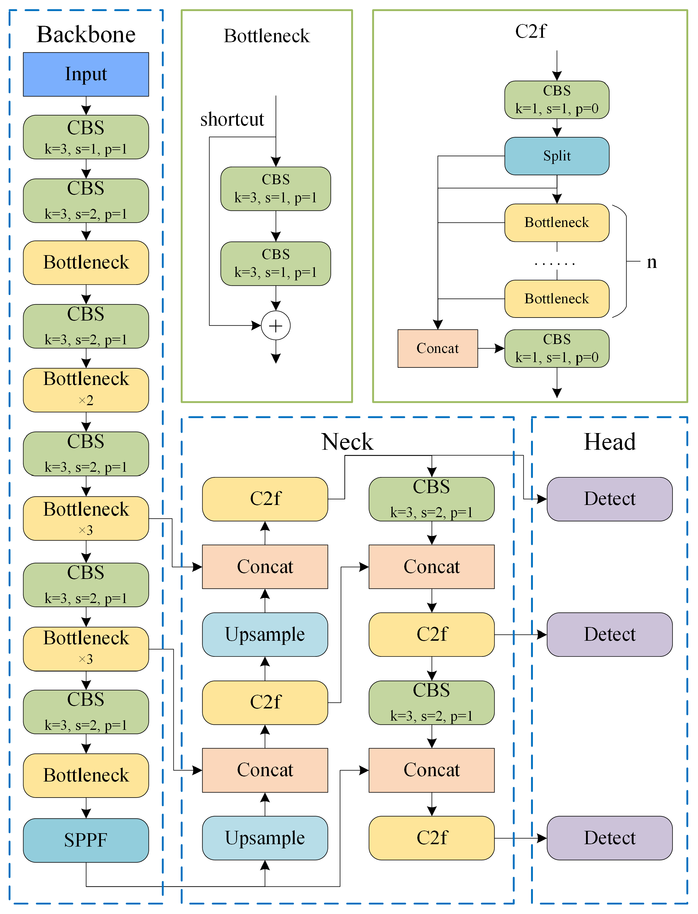
Our model structure is based on the Backbone, Neck, and Head structure of the YOLO model family designed for the corner detection task. After testing most of the models in the YOLO series, the YOLOv8 model showed suitable accuracy and inference speed (the detailed comparative experiments are described in Section 3.3). Therefore, improvements are made based on this model. The structure of our model is shown in Figure 4.
The improvement of the network model mainly went through the following processes. The coordinates of the corner points are essentially extracted based on the gradient information of the image, but the stride of the convolutional layers in YOLOv8 is 2, which is not conducive to perceiving continuous gradient changes in the image. Therefore, a CBS module with a stride of 1 was added to the first layer of the Backbone. In C2f module, the shortcut connection in Bottleneck module is similar to residual network, which helps to retain the gradient information from the lower layers to the higher layers, but the CBS module with convolutional kernel size of 1 and the split operation cause the gradient information to be compressed and separated. Therefore, the C2f module in Backbone is replaced with a Bottleneck module and an additional Bottleneck module is placed in the third layer. However, the C2f module is retained in Neck because the gradient information has been sufficiently extracted in Backbone, and Neck only needs to perform efficient information fusion. In addition, the width and depth of the network are appropriately adjusted to find a balance between the number of parameters and the model performance.

2.3.2. Physics-Informed Method

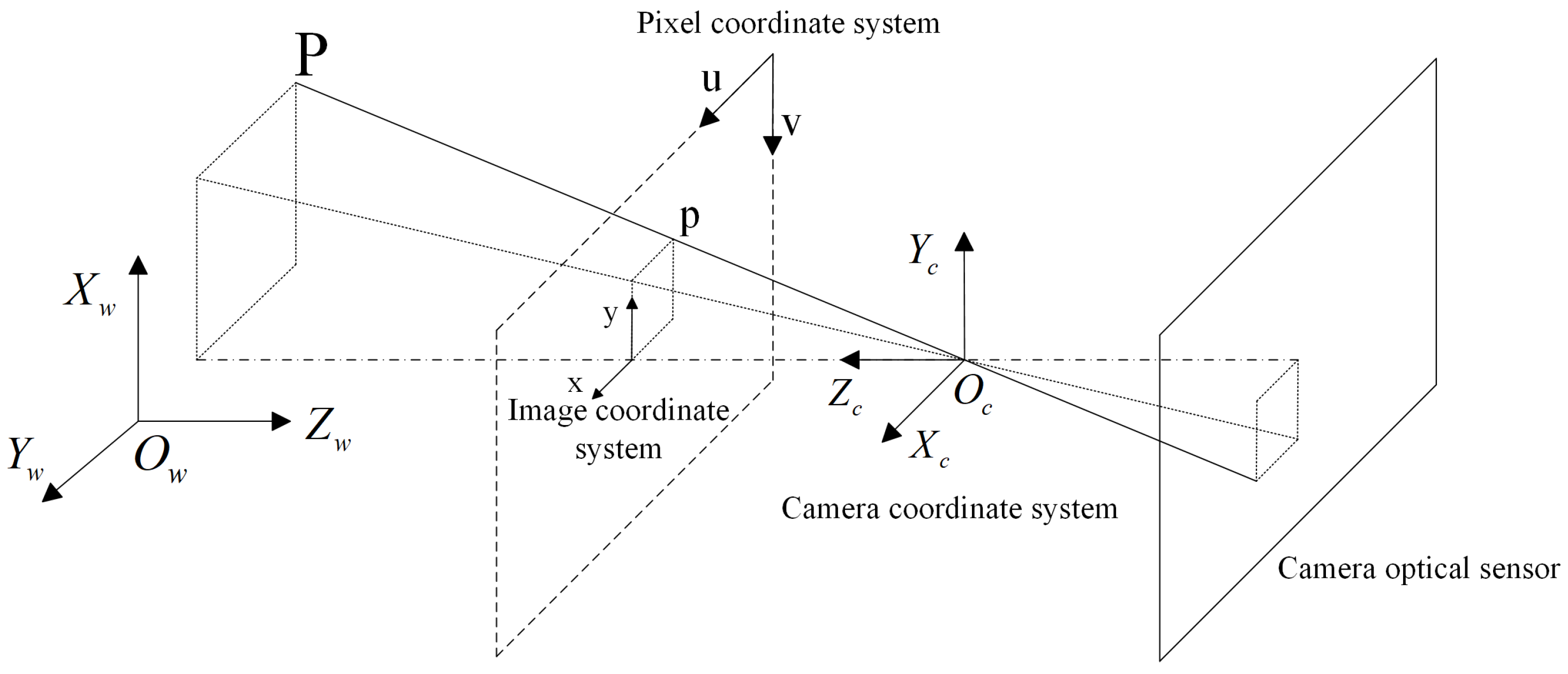
Figure 5 shows the physical model of the infrared camera used in this paper, including the geometric relationships between the world coordinate system, camera coordinate system, image coordinate system, and pixel coordinate system. The projection of light through the optical center (the origin of the camera’s coordinate system) onto the optical sensor is inverted, but this is automatically corrected by the camera when it is converted to a digital image, so we can move the imaging plane before the optical center, i.e., the plane of the dotted line in Figure 5.
Based on the imaging model in Figure 5, the process of projecting 3D world coordinate points to 2D pixel coordinate points can be described as follows:
s u ν 1 = K 0 R 3 × 3 T 3 × 1 0 1 X w Y w Z w 1 ,
where s is the scale factor. R 3 × 3 and T 3 × 1 are the external parameters of the camera that transform points under the 3D world coordinate system to the 3D camera coordinate system. K is the 3 × 3 camera intrinsic parameter matrix that transforms points under the 3D camera coordinate system to the 2D pixel coordinate system; this process essentially consists of two parts, the projection transformation ( T p r o j ) and the affine transformation ( T a f f ), which can be expressed as
K 0 = T a f f T p r o j = 1 / d x 0 c x 0 1 / d y c y 0 0 1 f 0 0 0 0 f 0 0 0 0 1 0 = f x 0 c x 0 0 f y c y 0 0 0 1 0 ,
where f x = f / d x , f y = f / d y , f is the focal length of the camera. c x and c y denote the horizontal and vertical pixel coordinates of the principal point, respectively. d x and d y are the actual width and height of each pixel corresponding to the optical sensor, respectively. In the actual camera calibration, the lens distortion also needs to be considered, which is generally described by the Brown–Conrady model [36,37], and mainly includes 2 parts: radial distortion and tangential distortion. The calculation method is as follows:
x ˜ y ˜ = x y 1 + k 1 x 2 + y 2 + k 2 x 2 + y 2 2 + k 3 x 2 + y 2 3 + 2 k 4 x y + k 5 3 x 2 + y 2 2 k 4 x y + k 5 3 y 2 + x 2 ,
where ( x , y ) denotes the image coordinates, k 1 , k 2 , and k 3 are radial distortion coefficients, and k 4 and k 5 are tangential distortion coefficients.
The well-known Zhang Zhengyou camera calibration method [13] provides a method to solve the camera internal parameters by coordinates of corners in multiple checkerboard pictures, and the optimal solution is obtained by minimizing the reprojection error through the Levenberg–Marquardt optimization algorithm. The objective function of the optimization is expressed as follows:
min K , D , R , T i = 1 N j = 1 M p i j p ^ ( K , D , R i , T i , P j ) 2 ,
where N and M denote the number of checkerboard pictures and the number of corners in each picture, respectively, p i j , p ^ , and P j denote the detected corner coordinate, the reprojected point coordinate, and the world coordinate of the corner, respectively, and D denotes the distortion coefficient ( k 1 , k 2 , k 3 , k 4 , k 5 ) .
According to (1)–(4), the physical model of the coordinates of the corner points in the image can be expressed as
p i j = f d i s t H K , R i , T i × P j , D ,
where p i j are the coordinates of the j th corner point in the i th image, P j are the world coordinates corresponding to p i j , H denotes the transformation matrix consisting of internal and external parameters, and the function f d i s t denotes the distortion model. From (5), it can be noted that, for corner points in the same image, the parameters K, R, T, and D are the same. For corner points in different images, the world coordinates P, the internal reference matrix K, and the distortion coefficient D are the same in their physical models. These consistencies constitute the intrinsic constraints that the corner points have on each other. The general target detection model training method only mines the target information from the perspective of image features, and it is difficult to learn the specific arrangement of corner points and the correlation of corner points in different images. Therefore, feedback based on physical information needs to be introduced to make the model predictions more consistent with the actual physical model.
The physical parameters of the camera used for the experiments are shown in Table 1, from the EXIF information of the photos, which can be linearly transformed to obtain the approximate camera internal parameter matrix K , as shown in Table 2. It should be noted that the Digital Zoom Ratio (1.19) in Table 1 refers to the digital magnification ratio of the image on the sensor rather than the equivalent optical magnification (8×) mentioned in Section 2.1, which is described in the camera’s user manual.
In the training process, the number of images in each batch is N and the number of corner points per image is M. The physical information feedback process is as follows:
  • Estimation of external parameters and distortion coefficients based on model predictions p i j and a priori physical information K :
    min R i , T i , D i = 1 N j = 1 M p i j f d i s t H K , R i , T i × P j , D ;
  • Substitute the estimated parameter into (5) to compute the expected corner point locations p i j , and calculate the prediction error and the intersection over union:
    d i j = | p i j p ^ i j | = [ d x i j , d y i j ] T I o U i j = ( w i j d x i j ) ( h i j d y i j ) 2 w i j h i j ( w i j d x i j ) ( h i j d y i j ) ,
    where w i j and h i j are the width and height of the predicted box, respectively;
  • Calculate the loss according to the conventional target detection loss function:
    L o s s = i = 1 N j = 1 M 1 I o U i j d i j 2 ( w i j + d x i j ) 2 + ( h i j + d y i j ) 2 .

2.4. Implementation Details

The model was trained and tested on Python 3.10, CUDA12.1, and Pytorch 2.3.1, and the hardware platforms were i9-13980HX and NVIDIA RTX4080 Laptop (12 GB). In the first stage of regular supervised training, the network was trained for 100 epochs starting with random weights, and the last 10 epochs were turned off for mosaic data augmentation [38]. The second stage of training based on physical information lasted 100 epochs, and, since no label was required, training was performed using the training set and the test set, respectively, in order to show that the trained model was still effective for brand new data. All training was completed using the SGD optimizer with a momentum of 0.937, an initial learning rate of 0.01, a final learning rate of 0.0001, and a batch size of 16.

3. Experimental Results and Discussion

3.1. Baselines

The baselines include OpenCV (4.11.0.86) [34] and the MATLAB (2022b) calibration toolbox [35], which are commonly used corner detection tools; the corner detection method based on EDLines straight-line detection proposed by Dan et al. [31], which relies on morphological operators; the LSCCL method, based on offset prediction using the EfficientNetV2 network, proposed by Zhu et al. [22], which detects feature points through deep learning; and the YOLO series end-to-end direct detection methods.

3.2. Evaluation Criteria

The main evaluation criteria we are concerned with in the corner detection results are the missed detection rate, the number of false positives, and the detection accuracy. The missed detection rate and the number of false positives reflect the robustness of the detection method. The accuracy of corner detection is reflected by the root mean square error (RMSE) and mean reprojection error (MRE) [12] of reprojected points, which are calculated as follows:
R M S E = j = 1 m i = 1 n p i j p i j 2 m n ,
M R E = j = 1 m i = 1 n p i j p i j m n .
The maximum reprojection error and the standard deviation of the reprojection error were also counted. These indicators reflect the accuracy of the camera calibration in a more comprehensive manner.

3.3. Comparison of Conventional YOLO Models

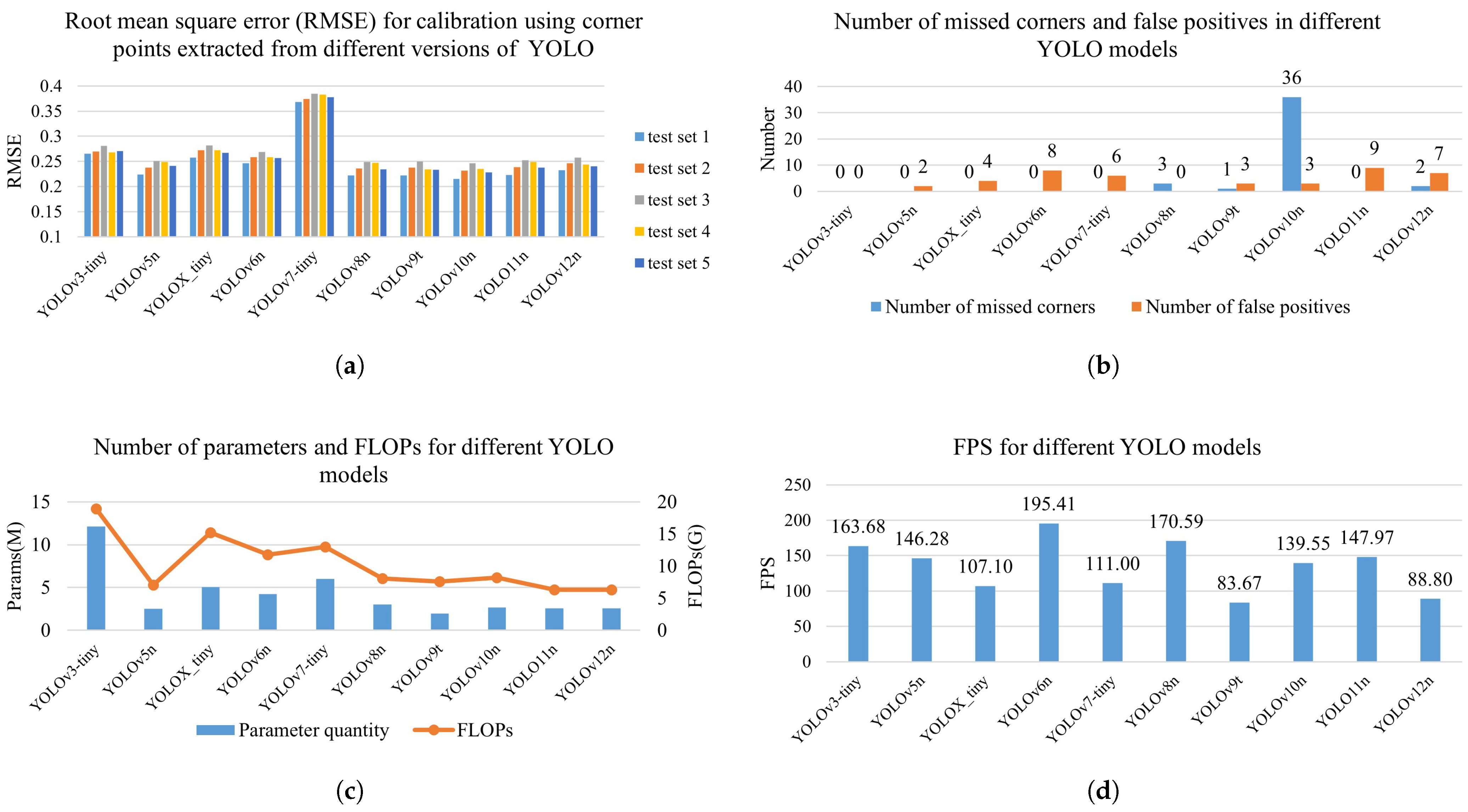
In the first stage of conventional supervised training, we first analyzed the corner detection performance of several lightweight versions of the conventional YOLO model and calculated the reprojection error of the calibration. Typically, the number of images used for camera calibration is about tens of images, so we divided the test set into five groups of 50 images each while avoiding chance in the test results. Figure 6a shows the root mean square error (RMSE) of each model on the five test sets. Figure 6b shows the sum of the number of missed detections and the number of false positives for the models, respectively. Figure 6c and Figure 6d show the scale and real-time performance of each model, respectively.
YOLOv10 performs best in terms of accuracy, but it has an unacceptable missed detection rate. The next highest in terms of accuracy is YOLOv9, but its training and inference speed is the slowest among all the models (about 1.7 times the training time of YOLOv8) and only about 0.9% more accurate than YOLOv8. Considering all the indicators, YOLOv8 is the most suitable, so we choose to improve on the basis of YOLOv8 model.

3.4. Ablation Experiment

The ablation experiment starts from the YOLOv8 model and is divided into four steps:
  • Adding a CBS module with a step size of 1 to be placed in the first layer of Backbone.
  • Replacing the C2f modules in Backbone with Bottleneck modules.
  • Add a Bottleneck module to be placed in the third layer of Backbone.
  • Starting from the second layer of the network, the width is adjusted to 1.5 times the original value, and the depth of the fourth, sixth, and eighth layers is increased by 1.
A comparison of the experimental results with the baseline method is shown in Table 3, where the error metrics are averaged over the five test sets, and the number of missed detections and false alarms are summed over the five test sets. The best values in Table 3 are marked in bold, and the second-best values are underlined. The results show that. after each improvement step, the error metrics of the model show a downward trend. Overall, the MRE of the improved model decreased by about 5%. Compared to the baselines, the missed detection rate of our method is very low, but the accuracy improvement is not obvious, which is mainly because the training labels have human uncertainties and the accuracy is only preserved to 0.5 pixels. At this point, the accuracy of the model is already slightly better than the MATLAB corner detection tool, indicating that the model has converged to the appropriate weights. Continuing to extend the training would only result in model overfitting. Table 4 shows the results of increasing the training by 50 epochs, and, even when training directly with the test set, the model accuracy still decreased. Therefore, the accuracy of the label is the bottleneck to further improving the accuracy of the model.
Our final model has 5.67 M parameters and 19.16 G floating-point operations per second (FLOPs). Upon testing on the self-built dataset, the real-time performance of the model is 169.7 FPS, which is almost the same compared to the YOLOv8n model. The added parameters come mainly from the convolution of the lower layers but do not have a significant impact on real-time performance.

3.5. Corner-Point Localization Experiment

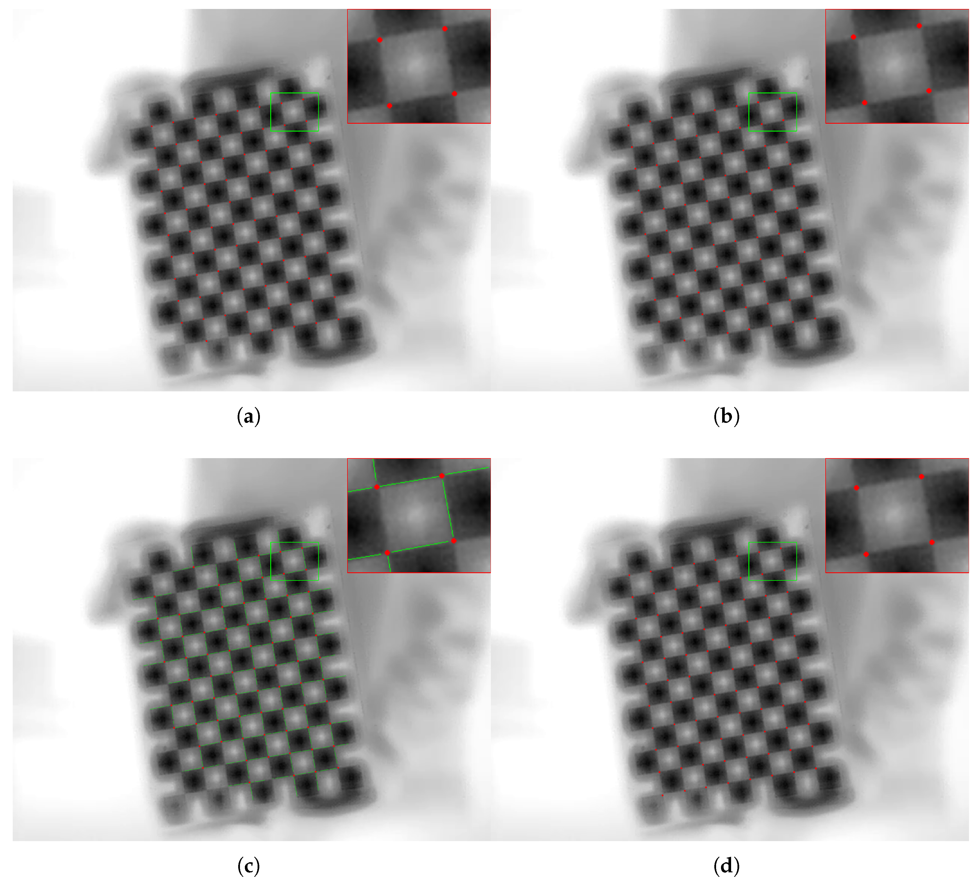
The second stage of physics-informed training was continued from the conventional training. Since labels were not required, training was performed using the training set and the test set separately. Table 5 shows the test results of our model and the YOLOv8n model after the second stage of training compared with the baseline methods. The best values in Table 5 are marked in bold, and the second-best values are underlined. The results show that, under the same training conditions, our model always outperforms YOLOv8n, which proves that our improvements to the model structure are effective. The MATLAB calibration toolbox has the highest accuracy in the baseline methods. After training based on the training set, the RMSE of our method decreased by 8.2% compared to the MATLAB calibration toolbox. After training based on the test set, our method decreased the RMSE by 30.3% compared to the MATLAB calibration toolbox. Table 6 shows the results of each method used for camera calibration, where the calibration results of our method are closest to those of direct linear transformation. Furthermore, our method demonstrates the best robustness. Among all the methods, our method has the lowest false negative rate and false positive rate, as shown in Table 5. For the calibrated image with blurred edges shown in Figure 7, only our method extracted all the corner points. In addition, the detection results of different methods also show differences in corner locations. In the MATLAB results (Figure 7a), the corner locations tend to be biased toward the lower right, while, in the LSCCL results (Figure 7b), the corner locations tend to be biased toward the upper left. Regarding the results of the EDLines-based method, Figure 7c shows significant random deviations in corner locations due to the accuracy of the line direction. Regarding the results of our method (Figure 7d), the corner locations are relatively uniform and do not show obvious deviations.
At this stage, physics-informed training only changes the model’s weights without changing the number of parameters in the model, so the model’s inference speed remains basically the same as before.

4. Discussion

Traditional YOLO models exhibit acceptable robustness in corner detection tasks but lack accuracy. The accuracy of corners in camera calibration tasks directly impacts the accuracy of the obtained parameters. After improving the network model, its corner detection accuracy is comparable to the best baseline method (the average reprojection error is reduced by approximately 5% compared to the MATLAB method). This indicates that general corner-detection neural networks not only outperform traditional methods in edge metrics such as false negative rate and false positive rate but can also achieve advanced levels of detection position accuracy. However, since this is achieved based on manually labeled data, the detection accuracy of the neural network is limited by the accuracy of the labels. The introduction of physical information in training stage 2 enables the corner-detection neural network to overcome the limitation of label accuracy, further reducing the error in detected corner coordinates. Since this training method no longer requires labels to calculate network loss, it is an unsupervised gradient descent training method that can be directly trained on any test data. The model trained through Stage 2 achieved higher accuracy than the model without Stage 2 training even on new test data outside the training data (Table 5), indicating that our method has good generalization ability. Among all the camera parameters obtained by the tested methods (Table 6), the camera parameters obtained by our method are the closest to the theoretical values (direct linear transformation), which further validates the proposed method. However, our method also includes the problem of increased training time because each batch of data needs to be fed with physical information once, leaving room for improvement in terms of efficiency. Overall, this method is expected to provide a new approach to optical camera calibration by improving the camera parameters obtained through the introduction of physical information about the camera.

5. Conclusions

In this paper, we propose a YOLO model for corner detection and an unsupervised physics-informed training method for accurate subpixel extraction of checkerboard corner points in an infrared camera calibration task. First, we analyze the performance of the traditional YOLO model in the corner-point detection task and improve the model’s ability to perceive the grayscale gradient information to overcome the problem of corner-point detection in low-signal-to-noise ratio infrared images. Then, the problem that the model accuracy is limited by the labels’ accuracy is solved by an unsupervised training method based on camera physical information. Compared with the classical methods based on local image features (MATLAB and OpenCV) and global image features (EDLines-based and LSCCL), our method is superior in robustness and calibration accuracy. The proposed target detection method based on the introduction of physical information provides an accurate and reliable approach for camera calibration of low-quality images. In this paper, we validated the proposed method in the task of calibrating high-magnification infrared cameras. In the future, this method is expected to be further extended to a wider range of optical camera calibration tasks.

Author Contributions

Conceptualization, Z.W. and Z.Z.; methodology, Z.W., Z.Z. and J.W.; software, Z.W. and J.W.; validation, P.W. and S.H.; formal analysis, Z.W. and J.W.; investigation, Z.Z.; resources, Z.Z. and J.W.; data curation, P.W., S.H. and Z.C.; writing—original draft preparation, Z.W. and Z.C.; writing—review and editing, Z.Z. and J.W.; visualization, Z.W. and Z.C.; supervision, Z.Z.; project administration, Z.Z. and Z.W.; funding acquisition, J.W. All authors have read and agreed to the published version of the manuscript.

Funding

This research was funded by the National Natural Science Youth Foundation of China, grant number 62201598.

Institutional Review Board Statement

Not applicable.

Informed Consent Statement

Not applicable.

Data Availability Statement

The original data presented in the study are openly available in GitHub at https://github.com/WuZY01/IR_camera_calibration.git (accessed on 20 August 2025).

Conflicts of Interest

The authors declare that they have no known competing financial interests or personal relationships that could have appeared to influence the work reported in this paper.

References

  1. Qu, Z.; Jiang, P.; Zhang, W. Development and application of infrared thermography non-destructive testing techniques. Sensors 2020, 20, 3851. [Google Scholar] [CrossRef]
  2. Manullang, M.C.T.; Lin, Y.H.; Lai, S.J.; Chou, N.K. Implementation of thermal camera for non-contact physiological measurement: A systematic review. Sensors 2021, 21, 7777. [Google Scholar] [CrossRef]
  3. Wang, J.; Tchapmi, L.P.; Ravikumar, A.P.; McGuire, M.; Bell, C.S.; Zimmerle, D.; Savarese, S.; Brandt, A.R. Machine vision for natural gas methane emissions detection using an infrared camera. Appl. Energy 2020, 257, 113998. [Google Scholar] [CrossRef]
  4. Perpetuini, D.; Filippini, C.; Cardone, D.; Merla, A. An overview of thermal infrared imaging-based screenings during pandemic emergencies. Int. J. Environ. Res. Public Health 2021, 18, 3286. [Google Scholar] [CrossRef] [PubMed]
  5. Mashekova, A.; Zhao, Y.; Ng, E.Y.K.; Zarikas, V.; Fok, S.C.; Mukhmetov, O. Early detection of the breast cancer using infrared technology–A comprehensive review. Therm. Sci. Eng. Prog. 2022, 27, 101142. [Google Scholar] [CrossRef]
  6. Wang, S.; Du, Y.; Zhao, S.; Gan, L. Multi-scale infrared military target detection based on 3X-FPN feature fusion network. IEEE Access 2023, 11, 141585–141597. [Google Scholar] [CrossRef]
  7. Chen, H.W.; Gross, N.; Kapadia, R.; Cheah, J.; Gharbieh, M. Advanced automatic target recognition (ATR) with infrared (IR) sensors. In Proceedings of the 2021 IEEE Aerospace Conference (50100), Big Sky, MT, USA, 6–13 March 2021; pp. 1–13. [Google Scholar] [CrossRef]
  8. Koide, K.; Menegatti, E. General hand–eye calibration based on reprojection error minimization. IEEE Robot. Autom. Lett. 2019, 4, 1021–1028. [Google Scholar] [CrossRef]
  9. Su, S.; Gao, S.; Zhang, D.; Wang, W. Research on the hand–eye calibration method of variable height and analysis of experimental results based on rigid transformation. Appl. Sci. 2022, 12, 4415. [Google Scholar] [CrossRef]
  10. Yuan, D.; Zhang, H.; Shu, X.; Liu, Q.; Chang, X.; He, Z.; Shi, G. Thermal infrared target tracking: A comprehensive review. IEEE Trans. Instrum. Meas. 2023, 73, 5000419. [Google Scholar] [CrossRef]
  11. Hou, F.; Zhang, Y.; Zhou, Y.; Zhang, M.; Lv, B.; Wu, J. Review on infrared imaging technology. Sustainability 2022, 14, 11161. [Google Scholar] [CrossRef]
  12. ElSheikh, A.; Abu-Nabah, B.A.; Hamdan, M.O.; Tian, G.Y. Infrared camera geometric calibration: A review and a precise thermal radiation checkerboard target. Sensors 2023, 23, 3479. [Google Scholar] [CrossRef]
  13. Zhang, Z. A flexible new technique for camera calibration. IEEE Trans. Pattern Anal. Mach. Intell. 2000, 22, 1330–1334. [Google Scholar] [CrossRef]
  14. Usamentiaga, R.; Garcia, D.F.; Ibarra-Castanedo, C.; Maldague, X. Highly accurate geometric calibration for infrared cameras using inexpensive calibration targets. Measurement 2017, 112, 105–116. [Google Scholar] [CrossRef]
  15. Rosten, E.; Drummond, T. Machine learning for high-speed corner detection. In Proceedings of the Computer Vision–ECCV 2006: 9th European Conference on Computer Vision, Graz, Austria, 7–13 May 2006; Proceedings, Part I 9. Springer: Berlin/Heidelberg, Germany, 2006; pp. 430–443. [Google Scholar]
  16. Rosten, E.; Porter, R.; Drummond, T. Faster and better: A machine learning approach to corner detection. IEEE Trans. Pattern Anal. Mach. Intell. 2010, 32, 105–119. [Google Scholar] [CrossRef] [PubMed]
  17. Du, F.; Liu, P.; Zhao, W.; Tang, X. Correlation-guided attention for corner detection based visual tracking. In Proceedings of the 2020 IEEE/CVF Conference on Computer Vision and Pattern Recognition (CVPR), Seattle, WA, USA, 13–19 June 2020; pp. 6836–6845. [Google Scholar] [CrossRef]
  18. Wu, H.; Wan, Y. A highly accurate and robust deep checkerboard corner detector. Electron. Lett. 2021, 57, 317–320. [Google Scholar] [CrossRef]
  19. Song, W.; Zhong, B.; Sun, X. Building corner detection in aerial images with fully convolutional networks. Sensors 2019, 19, 1915. [Google Scholar] [CrossRef] [PubMed]
  20. Dantas, M.S.M.; Bezerra, D.; de Oliveira Filho, A.T.; Barbosa, G.; Rodrigues, I.R.; Sadok, D.H.; Kelner, J.; Souza, R. Automatic template detection for camera calibration. Res. Soc. Dev. 2022, 11, e173111436168. [Google Scholar] [CrossRef]
  21. Kang, J.; Yoon, H.; Lee, S.; Lee, S. Sparse checkerboard corner detection from global perspective. In Proceedings of the 2021 IEEE International Conference on Signal and Image Processing Applications (ICSIPA), Kuala Terengganu, Malaysia, 13–15 September 2021; pp. 12–17. [Google Scholar] [CrossRef]
  22. Zhu, H.; Zhou, Z.; Liang, B.; Han, X.; Tao, Y. Sub-pixel checkerboard corner localization for robust vision measurement. IEEE Signal Process. Lett. 2023, 31, 21–25. [Google Scholar] [CrossRef]
  23. Redmon, J.; Divvala, S.; Girshick, R.; Farhadi, A. You only look once: Unified, real-time object detection. In Proceedings of the 2016 IEEE Conference on Computer Vision and Pattern Recognition (CVPR), Las Vegas, NV, USA, 27–30 June 2016; pp. 779–788. [Google Scholar] [CrossRef]
  24. Xicai, L.; Qinqin, W.; Yuanqing, W. Binocular vision calibration method for a long-wavelength infrared camera and a visible spectrum camera with different resolutions. Opt. Exp. 2021, 29, 3855–3872. [Google Scholar] [CrossRef]
  25. Wang, G.; Zheng, H.; Zhang, X. A robust checkerboard corner detection method for camera calibration based on improved YOLOX. Front. Phys. 2022, 9, 819019. [Google Scholar] [CrossRef]
  26. Son, M.; Ko, K. Multiple projector camera calibration by fiducial marker detection. IEEE Access 2023, 11, 78945–78955. [Google Scholar] [CrossRef]
  27. Harris, C.; Stephens, M. A combined corner and edge detector. In Proceedings of the Alvey Vision Conference, Manchester, UK, 15–17 September 1988; Volume 15, pp. 10–5244. [Google Scholar]
  28. Shi, D.; Huang, F.; Yang, J.; Jia, L.; Niu, Y.; Liu, L. Improved Shi–Tomasi sub-pixel corner detection based on super-wide field of view infrared images. Appl. Opt. 2024, 63, 831–837. [Google Scholar] [CrossRef] [PubMed]
  29. Shi, J. Good features to track. In Proceedings of the IEEE Conference on Computer Vision and Pattern Recognition, Seattle, WA, USA, 21–23 June 1994; IEEE: Piscataway, NJ, USA, 1994; pp. 593–600. [Google Scholar]
  30. Du, X.; Jiang, B.; Wu, L.; Xiao, M. Checkerboard corner detection method based on neighborhood linear fitting. Appl. Opt. 2023, 62, 7736–7743. [Google Scholar] [CrossRef] [PubMed]
  31. Dan, X.; Gong, Q.; Zhang, M.; Li, T.; Li, G.; Wang, Y. Chessboard corner detection based on EDLines algorithm. Sensors 2022, 22, 3398. [Google Scholar] [CrossRef]
  32. Lü, X.; Meng, L.; Long, L.; Wang, P. Comprehensive improvement of camera calibration based on mutation particle swarm optimization. Measurement 2022, 187, 110303. [Google Scholar] [CrossRef]
  33. Lawal, Z.K.; Yassin, H.; Lai, D.T.C.; Che Idris, A. Physics-informed neural network (PINN) evolution and beyond: A systematic literature review and bibliometric analysis. Big Data Cognit. Comput. 2022, 6, 140. [Google Scholar] [CrossRef]
  34. Bradski, G.; Kaehler, A. Learning OpenCV: Computer Vision with the OpenCV Library; O’Reilly: Sebastopol, CA, USA, 2008. [Google Scholar]
  35. Fetić, A.; Jurić, D.; Osmanković, D. The procedure of a camera calibration using Camera Calibration Toolbox for MATLAB. In Proceedings of the 35th International Convention MIPRO, Opatija, Croatia, 21–25 May 2012; pp. 1752–1757. [Google Scholar]
  36. Conrady, A.E. Lens-systems, decentered. Mon. Not. Roy. Astron. Soc. 1919, 79, 384–390. [Google Scholar] [CrossRef]
  37. Brown, D.C. Decentering distortion of lenses. Photogramm. Eng. 1966, 32, 444–462. [Google Scholar]
  38. Bochkovskiy, A.; Wang, C.Y.; Liao, H.Y.M. Yolov4: Optimal speed and accuracy of object detection. arXiv 2020, arXiv:2004.10934. [Google Scholar] [CrossRef]
Figure 1. Experimental materials, equipment, and self-constructed dataset: (a) heatable calibration board; (b) DJI H20N payload; (c) Examples of training data, including original images (left side of dotted line) and enhanced images (right side of dotted line).
Photonics 12 00847 g001
Figure 2. Description of commonly used conventional methods: (a) conventional subpixel corner-point extraction method; (b) corner extraction result in an infrared image using the conventional subpixel corner extraction method.
Photonics 12 00847 g002
Figure 3. Two-stage training process.
Photonics 12 00847 g003
Figure 4. Our YOLO model for corner detection.
Photonics 12 00847 g004
Figure 5. Imaging model of pinhole camera.
Photonics 12 00847 g005
Figure 6. Performance comparison of different versions of YOLO models in corner detection tasks: (a) Corner detection accuracy. (b) Corner detection robustness. (c) Number of parameters and computation. (d) Inference speed.
Photonics 12 00847 g006
Figure 7. The corner detection results (red dots) of the same image by different methods: (a) MATLAB. (b) LSCCL. (c) EDLines-based. (The green line indicates the detected straight line.) (d) Ours.
Photonics 12 00847 g007
Table 1. Camera details.
Camera Performance Specifications
ModelZH20N
Focal Length44.5 mm
Image Width640 pixels
Image Length512 pixels
Digital Zoom Ratio1.19
Focal Length In 35 mm Film196 mm
Table 2. Linear approximation of camera intrinsic parameters.
parameter f x f y c x c y
numerical4418.26754418.2675320.0256.0
Table 3. Results of ablation experiments.
Corner Detection MethodRMSEMREMaximum ErrorStandard DeviationMissed CornersFalse Positive Corners
YOLOv8n0.23770.19011.55750.142730
After step 10.23460.18681.46840.141921
After step 20.23340.18671.43470.140103
After step 30.23280.18621.59400.139712
After step 4 (Ours)0.22770.18071.60090.138421
MATLAB [35]0.23320.18351.86450.143845 (0.2%)0
OpenCV [34]0.30270.25021.45040.170218,656 (84.8%)0
Table 4. Experimental results with an increase of 50 training epochs.
Corner Detection MethodTraining DataRMSEMREMaximum ErrorStandard DeviationMissed CornersFalse Positive Corners
OursTraining set0.25720.21001.61330.148521
Test set0.24520.19771.65790.145000
Table 5. The average test results based on five test sets.
Corner Detection MethodTraining DataEpochsRMSEMREMaximum ErrorStandard DeviationMissed CornersFalse Positive Corners
OursTraining stage 1Training set1000.22770.18071.60090.138421
+Training stage 2Training set500.21740.17121.58000.134020
1000.21400.16911.50300.131222
Test set500.20600.15971.52920.130100
1000.16250.12781.23180.100300
YOLOv8n+Training stage 2Training set500.23250.18471.55950.141140
1000.21910.17251.55390.135130
Test set500.21440.16691.50800.134501
1000.18640.14521.36980.116801
MATLAB [35]0.23320.18351.86450.143845 (0.2%)0
OpenCV [34]0.30270.25021.45040.170218,656 (84.8%)0
LSCCL [22]0.25930.21211.64630.14921714
EDLines-based [31]0.39550.32103.55410.23082445 (11.1%)19
Table 6. Calibration results of different methods.
Parameter f x /Pixel f y /Pixel c x /Pixel c y /Pixel k 1 k 2 k 3 k 4 k 5
Direct linear transformation4418.2684418.268320.000256.000
MATLAB [35]4527.6194533.591288.734249.2683.45−512.70 5.88 × 10 4 1.23 × 10 3 3.41 × 10 4
OpenCV [34]4474.0114487.650308.506173.5802.56−219.09 2.23 × 10 4 3.88 × 10 2 6.07 × 10 3
LSCCL [22]4545.4334551.421279.798244.8233.28−431.80 4.95 × 10 4 6.26 × 10 4 6.53 × 10 3
EDLines-based [31]4505.9264510.617281.054254.4832.95−349.50 4.58 × 10 4 5.17 × 10 3 4.53 × 10 3
Ours4489.0674496.667307.170268.9422.98−376.13 4.99 × 10 4 9.72 × 10 3 1.06 × 10 2
Disclaimer/Publisher’s Note: The statements, opinions and data contained in all publications are solely those of the individual author(s) and contributor(s) and not of MDPI and/or the editor(s). MDPI and/or the editor(s) disclaim responsibility for any injury to people or property resulting from any ideas, methods, instructions or products referred to in the content.