Article

Improved Ultra-Dense Connection Provision Capability of Concurrent Upstream and Direct Inter-ONU Communication IMDD PONs by P2MP Flexible Optical Transceivers

1
College of Electronics and Information Engineering, Shanghai University of Electric Power, Shanghai 200090, China
2
DSP Centre of Excellence, School of Computer Science and Engineering, Bangor University, Bangor LL57 1UT, UK
3
Key Laboratory of Specialty Fiber Optics and Optical Access Networks, Shanghai University, Shanghai 200444, China
*
Author to whom correspondence should be addressed.
Photonics 2025, 12(9), 838; https://doi.org/10.3390/photonics12090838
Submission received: 13 July 2025 / Revised: 18 August 2025 / Accepted: 21 August 2025 / Published: 22 August 2025
(This article belongs to the Section Optical Communication and Network)

Abstract

To cost-effectively meet 6G latency requirements, concurrent upstream and direct inter-optical network unit (ONU) communication passive optical networks (PONs) based on flexible point-to-multipoint (P2MP) optical transceivers and intensity modulation and direct detection (IMDD) have been reported to enable direct communications among different ONUs within the same PON without passing data to the optical line terminal (OLT). However, the previously reported P2MP transceivers suffer from high DSP complexity for establishing ultra-dense connections. For such application scenarios, the PON’s remote nodes also have high inter-ONU signal power losses. To effectively solve these technical challenges, this paper experimentally showcases (a) new P2MP transceivers by utilizing parallel multi-channel aggregation/de-aggregation and advanced extended Gaussian function (EGF)-based orthogonal digital filter banks, along with (b) low inter-ONU signal power loss-remote nodes. By introducing these two techniques into a 27 km, >54.31 Gbit/s concurrent upstream and direct inter-ONU communication IMDD PON, comprehensive experimental explorations of the PON’s performances were undertaken for the first time. The remote node is capable of supporting 128 ONUs. The results show that the new P2MP transceivers lead to >75% (>40%) reductions in overall transmitter (receiver multi-channel de-aggregation) DSP complexity, and they can also equip the PONs with an enhanced capability of providing ultra-dense connections. The experimental results also show that the PON allows each ONU to flexibly change its upstream and inter-ONU communication channel count without considerably compromising its performance. Therefore, the PON outperforms those of previously reported works in terms of ensuring low DSP complexity, highly robust transmission performance, and enhanced capabilities of flexibly accommodating numerous applications with diverse requirements regarding traffic characteristics, thus making it suitable for ultra-dense connection application scenarios.

1. Introduction

In comparison with 5G networks, 6G networks are envisaged to have considerably enhanced signal transmission capacities and network operation flexibility in order to dynamically provide high-speed, low-latency and on-demand connections capable of supporting a vast number of applications with diverse requirements regarding traffic characteristics [1,2,3]. For practically implementing 6G access networks, intensity modulation and direct detection (IMDD) passive optical networks (PONs) have been widely considered to be a cost-effective solution for deploying their fronthaul links between a baseband unit (BBU) and remote radio heads (RRHs) [4,5], where the PON’s optical line terminal (OLT) and optical network units (ONUs) are often located in the BBU and RRHs, respectively. In such a PON-based 6G access network, for many latency-sensitive applications such as industrial automation [6,7], end-users need to communicate directly with each other without involving the OLT. However, in a conventional PON, to establish communications between end-users, user data from the source ONU needs to be sent to the OLT before reaching the destination ONUs. This gives rise to a round-trip fiber propagation delay that may be comparable to the latency introduced by corresponding high-layer protocols [8].
To cost-effectively address the above technical challenges, a concurrent upstream and direct inter-ONU communication IMDD PON has been reported recently [9], where, in addition to upstream communications from the ONUs to the OLT, highly desired direct inter-ONU communications can also be dynamically established between different ONUs within the same PON without involving the OLT. This is achieved by utilizing a passive optical coupler (OC)-based remote node (RN) to enable the RN to redirect and broadcast the inter-ONU communication signals from the source ONUs to the destination ONUs, while still passing all the ONU’s upstream signals to the OLT [9]. In addition, the cost-effectiveness and network operation flexibility of the PON can also be further improved if, in each individual ONU and OLT, use is made of a point-to-multipoint (P2MP) optical transceiver incorporating cascaded multi-channel aggregation/de-aggregation operations based on inverse fast Fourier transform (IFFT)/fast Fourier transform (FFT) [9,10].
However, to practically implement the P2MP optical transceiver-based concurrent upstream and direct inter-ONU communication IMDD PONs in latency-sensitive and ultra-dense connection application scenarios, three major technical barriers must be overcome, of which two are related to the P2MP optical transceiver design, and one is associated with the RN architecture. Firstly, in the previously reported P2MP optical transceivers, the cascaded multi-channel aggregation/de-aggregation process can just aggregate/de-aggregate a single channel at each stage, the simultaneous accommodation of ultra-dense connections requires a large number of channel aggregation/de-aggregation stages to be cascaded. Considering the fact that the IFFT/FFT size of each stage increases exponentially with channel count [10], the aggregation/de-aggregation of a large number of channels unavoidably leads to extremely high transceiver DSP complexity. Secondly, when the channel count is large, the channel interference effect becomes non-negligible, thus degrading the overall transmission performances of both the P2MP optical transceivers and the PON [10]. Thirdly, in the experimental demonstrations reported in [9], a 3-by-N OC-based RN [11,12,13] is utilized, which introduces an unacceptable inter-ONU signal power loss of as high as 49.3 dB for cases where 128 ONUs are accommodated because the inter-ONU signals pass the RN twice. Of equal importance is the fact that the inter-ONU signal power loss increases with increasing ONU count.
To cost-effectively overcome the aforementioned three technical barriers, this paper proposes and experimentally demonstrates the effectiveness of a novel P2MP optical transceiver, termed as a new P2MP transceiver, throughout the paper, for implementation in the concurrent upstream and direct inter-ONU communication IMDD PON. The new P2MP transceiver employs (1) a parallel channel aggregation/de-aggregation operation to allow multiple (>2) parallel channels to be aggregated/de-aggregated at each stage and (2) advanced extended Gaussian function (EGF)-based rectangular orthogonal digital filters [14] for locating signals at the desired radio frequency (RF) spectral regions. Compared to the previously reported P2MP optical transceiver [9,10], the new design can not only reduce the overall transmitter (receiver multi-channel de-aggregation) DSP complexity by >75% (>40%) but also equip the demonstrated PONs with significantly enhanced network operation flexibility and performance robustness. Finally, effort is also made to experimentally evaluate a modified RN architecture suffering significantly low inter-ONU signal power loss in an environment capable of supporting 128 ONUs. As such, this work effectively addresses the aforementioned three technical barriers associated with the previously reported techniques [9,10], which is the main novelty and contribution of this work.
By incorporating the new P2MP optical transceivers in both the ONUs and OLTs, as well as the modified RN architecture, in this paper, a 27 km, >54.31 Gbit/s concurrent upstream and direct inter-ONU communication IMDD PON is experimentally demonstrated, for the first time, based on which comprehensive experimental explorations of the new P2MP optical transceivers and the modified RN architecture are undertaken. Our experimental results indicate that the proposed PONs allow each ONU to flexibly change its inter-ONU and upstream channel counts without considerably compromising its maximum achievable transmission capacities. Compared to previously reported results [9], the PON is superior in terms of ensuring low DSP complexity, highly robust transmission performance, and improved network operation flexibility.
Comprehensive comparisons of the techniques of various concurrent inter-ONU and upstream communication IMDD PONs incorporating OC-based RNs and different optical transceivers [9,11,12,13,15,16,17] are presented in Table A1 in Appendix A. In comparison with other existing inter-ONU communication PONs’ RN designs using optical switches [18,19], cyclic arrayed waveguide gratings [20,21], cascaded optical interleavers [22], and their combinations [23], the OC-based modified RNs considered in this work are simple, low-cost, and transparent to wavelengths.

2. Operating Principle

2.1. Network Architecture

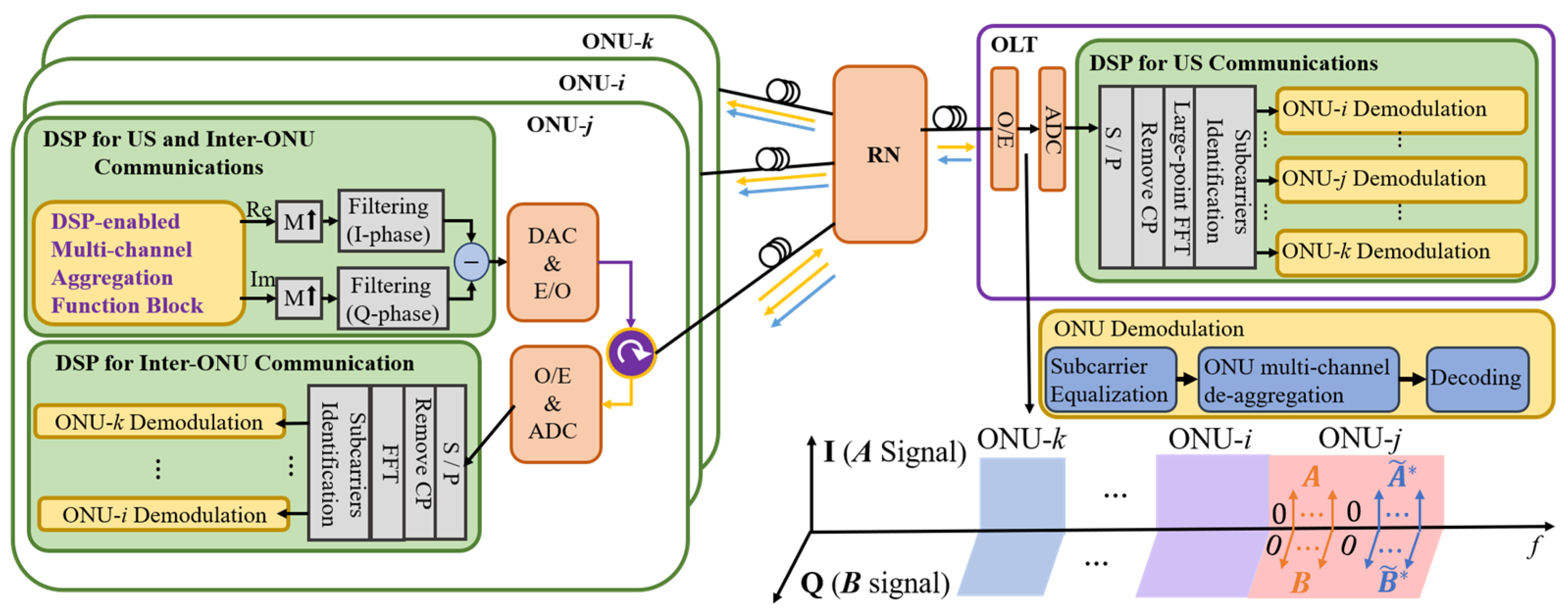
A schematic diagram of the concurrent direct inter-ONU and upstream communication IMDD PONs is illustrated in Figure 1, and the modified RN architecture is shown in Figure 2. The DSP-enabled multi-channel aggregation/de-aggregation process is presented in Section 2.2.
As seen in Figure 1, in each ONU DSP, the multi-channel aggregation function block produces a complex-valued baseband signal consisting of multiple inter-ONU and upstream channels. Following a procedure similar to that reported in [9,10], the produced signal is then digitally up-sampled by a factor of M and finally passes a pair of EGF-based orthogonal digital filters. After combining the outputs of the orthogonal digital filters, a real-valued signal located in the desired RF spectral region is generated, which, after passing through a digital-to-analog converter (DAC) and an intensity modulator, is converted into an optical signal and finally launched into the fiber link.
At the RN, as seen in Figure 2, the optical signals from various ONUs are launched in a corresponding sub-structure via the P1 port, where the optical signal is passively split into two copies: one sent to the OLT via the P2 port and OC-1 and the other redirected and broadcast to all the ONUs via the P3 port, OC-2, and the P4 port of the other sub-structure. Detailed RN operating principles can be found in [9]. According to the theoretical analyses in [9], for PONs with total numbers of ONU of N = 8, 16, 32, 64, and 128, the resulting inter-ONU power losses are 18.75, 22.03, 25.33, 29.5, and 32.65 dB, respectively. Compared to the conventional OC-based inter-ONU communication PON RN designs (inter-ONU signals pass a 3-by-N OC twice) [11,12,13], the modified RN can reduce inter-ONU signal power losses by approximately 2.75, 6.03, 9.33, 13.5, and 16.65 dB, respectively [9], as experimentally verified in Section 4.1.
All the OLT and ONU receivers employ their DSP demodulation procedures similarly to those employed in their counterparts. As seen in Figure 1, a photodetector detects all optical signals from different ONUs. Following the procedure detailed in Section 2.2, each ONU’s data samples are identified and then input into the corresponding ONU multi-channel de-aggregation module to obtain the desired user data.

2.2. DSP-Enabled Multi-Channel Aggregation/De-Aggregation

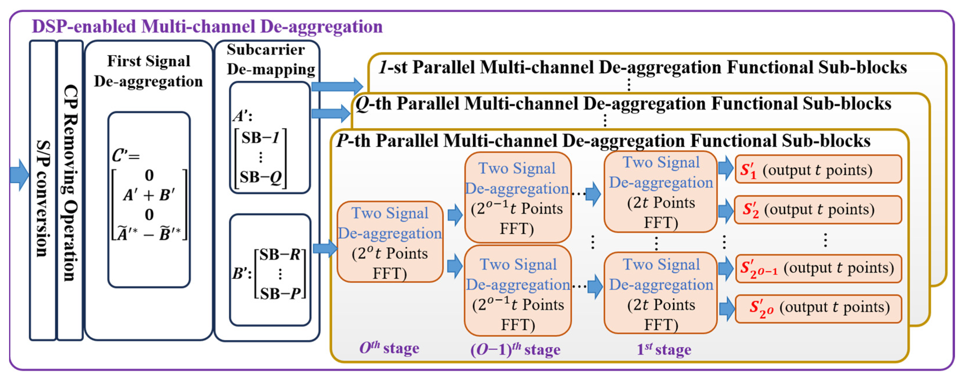
The new P2MP transceiver’s multi-channel aggregation and de-aggregation DSP processes are illustrated in Figure 3 and Figure 4, respectively. As seen in Figure 3, in each ONU, its aggregation process can contain multiple independent parallel channel aggregation sub-blocks, and each sub-block can process different numbers of channels (either for inter-ONU or upstream communications), and thus, each one has a different number of output samples.
Taking the P-th sub-block as an example, the sub-block has O stages of parallel IFFT-based two-signal aggregation operations to aggregate 2O channels. Assuming each channel has t input samples, which can be encoded by arbitrary modulation formats including quadrature amplitude modulation (QAM) and phase shift keying (PSK), each two-signal aggregation operation implemented at the i-th stage can be expressed as
Z = F 1 X + Y ,   X ~ Y ~
where X = [x1, x2,…, xw] and Y = [y1, y2,…, yw], (w= 2it) are two input signals. ~ represents the flip operation, i.e.,   X ~ = [ xw,…x2, x1]. Z = [z1, z2,…, z2w] is the output of the two-signal aggregation operation. F 1 stands for the IFFT operation. To simplify the analysis, we also define the input of the IFFT operation in Equation (1) as [ Z 1 , Z 2 ] , where Z 1 = X + Y ,     Z 2 = [ X ~ Y ~ ] .
The outputs of each parallel multi-channel aggregation sub-block are mapped into one subset of subcarriers, denoted as the A signal or B signal. As shown in the signal spectrum in Figure 1, after orthogonal digital filtering, the A signal (B signal) corresponds to the in-phase (quadrature-phase) subcarriers in the produced orthogonal signal bands. The subcarrier is defined as the input to the IFFT operation in the final signal aggregation stage. The A and B signals are then combined to ensure we have the following:
C = 0 , A + B , 0 , A * ~ B * ~ = [ 0 , C 1 , 0 , C 2 ]
where * is the conjugate operation. After the IFFT operation, cyclic prefix (CP) insertion and parallel-to-serial (P/S) conversion, a complex baseband signal is produced, whose real and imaginary parts contain A and B signals, respectively.
In the receiver DSPs, the ONU multi-channel de-aggregation is presented in Figure 4. In the first signal de-aggregation stage, the received A and B signals (i.e., A and B) are obtained by the following:
A = C 1 + C 2 * ~ ;   B = C 1 C 2 * ~
where C 1 and C 2 are the received C1 and C2 signals. After subcarrier de-mapping, the received samples are launched into their corresponding parallel multi-channel de-aggregation sub-blocks. Taking the P-th sub-block as an example again, it contains O stages of multiple parallel FFT-based two-signal de-aggregation operations. For the i-th stage, each two-signal de-aggregation first implements a 2w-point FFT operation and then separates the aggregated two signals following a formula expressed as follows:
X = Z 1 + Z 2 ~ ;   Y = Z 1 Z 2 ~
where X and Y are the outputs of the two-signal de-aggregation operation. Z = Z 1 , Z 2 is the corresponding input signal. After having completed the O stages of the two-signal de-aggregation operations, 2O channels are finally separated.

2.3. Transceiver DSP Complexity

From the above descriptions, and for the P-th parallel multi-channel aggregation/de-aggregation sub-block, its DSP complexity, which is defined as the required multiplication operation count [10], can be calculated by
C O = η = 1 O 2 O 1 t log 2 ( 2 η t )
It can be found that the sub-block DSP complexity is determined by the stage count (i.e., O) and each channel’s sample count (i.e., t), which may be different from sub-block to sub-block, and this gives rise to different sub-block DSP complexities.
For analyzing the maximum overall transmitter DSP complexity, for simplicity, we assume that (1) each channel has a sample count of t and (2) that the A and B signals have identical subcarrier allocations, i.e., the A and B signal’s available subcarriers can be classified into (β + 1) groups, and their corresponding subcarrier counts are {21t, …, 2βt, 2t − 1}, while their supported channel counts are {21, …, 2β, 1}. As such, the overall channel count is (2β+2 2). The overall transmitter DSP complexity can be obtained by
C m a x = 2 β + 3 t M ξ 1 + φ + 2 β + 1 t log 2 ( 2 β + 2 t ) + δ = 1   β η = 1 δ 2 δ t log 2 2 η t
where M, ξ , and φ stand for the digital up-sampling factor, the digital filter length, and the CP length, respectively. The first term is the digital filtering-induced DSP complexity. The remaining two terms are the DSP complexities induced by the A and B signal aggregations and all the parallel multi-channel aggregations, respectively. The receiver parallel multi-channel de-aggregation DSP complexity can be calculated by the third term.
On the other hand, for a specific parallel multi-channel aggregation/de-aggregation sub-block, its DSP latency is determined by its stage count and corresponding IFFT/FFT sizes [24]. The channels aggregated by the same sub-block not only equally share the allocated bandwidth but also have similar multi-channel aggregation/de-aggregation DSP latencies. While for different sub-blocks, their different subcarrier/channel/stage counts can lead to different channel bandwidth and channel aggregation/de-aggregation DSP latencies. The above statements are verified in Section 3.2. It should also be noted that when all the parallel multi-channel aggregation/de-aggregation sub-blocks are de-activated (i.e., all the channels’ samples are directly mapped onto the A and B signal subcarriers), the resulting multi-channel aggregation/de-aggregation operation has the lowest transceiver DSP complexity and latency. As such, flexible and dynamic channel allocations can be made by selecting the suitable multi-channel aggregation sub-blocks for each individual application according to its specific traffic requirements (such as bandwidth and latency).
In addition, to effectively reduce channel interference and also achieve highly robust transmission performance, in practically implementing subcarrier mapping, adaptive subcarrier allocations can be utilized to allocate subcarriers suffering negligible (relatively large) distortions for sub-blocks aggregating more (less) channels. This can also increase the overall channel count that the transceivers can aggregate, as verified in Section 3.3.
The multi-channel aggregation and de-aggregation DSP, which is of a hybrid cascaded and parallel signal processing structure, can be practically implemented by using the superior parallel processing capabilities of field-programmable gate arrays (FPGAs). To practically implement real-time EGF-based orthogonal digital filter banks, a parallel digital filter architecture [25] can be used to achieve the high FPGA resource utilization efficiency by eliminating the multiplication operations for zero samples produced by digital up-sampling operations. Compared to the previously reported transceivers [9], the new transceivers have reduced DSP complexity, thus leading to improved FPGA resource utilization efficiency and reduced power consumption.
The P2MP transceivers potentially transform the access networks into FDM networks, offering excellent network upgradability and scalability [10]. When the activated ONU count increases (either adding new ONUs or activating sleep ONUs), the activated ONUs can use unoccupied radio frequencies without considerably affecting the inter-ONU and upstream communications of all other existing activated ONUs.

3. New P2MP Transceiver-Induced Performance Improvements

To evaluate the new P2MP transceivers, this section details how we utilized a 25 km, >53.9 Gbit/s IMDD upstream PON, as illustrated in Figure 5, to experimentally compare the performances between the proposed new P2MP transceiver and the previously reported P2MP transceivers in [9,10].

3.1. Experimental Setups and Parameters

At the transmitter side, a dual-channel arbitrary waveform generator (AWG) generates two ONU upstream signals. The signal of ONU1 (ONU2) occupies a spectral region between 0 GHz and 6.25 GHz (6.25 GHz to 12.5 GHz). For the new P2MP transceivers, each ONU transmits 14 independent channels. For each ONU, the A and B signals have identical subcarrier allocations, i.e., of the 31 available subcarriers, 7 subcarriers are allocated for a single channel (CH1), 16 subcarriers are used to convey two channels (CH2 and CH3, with four input samples/channel) aggregated by a single eight-point IFFT operation, and the remaining 8 subcarriers are allocated for four channels (CH4 and CH5, as well as CH6 and CH7, with four input samples per channel) aggregated by implementing two stages of IFFT operations with operation sizes of 8 and 16, respectively. After multi-channel aggregation, each ONU applies a digital up-sampling operation, an EGF-based orthogonal digital filtering operation, a 1.2× digital oversampling operation, an ONU timing adjustment operation, and a signal clipping operation. The key parameters are listed in Table 1, in which the EGF digital filter parameters identified in [14] are optimum. The channel bitrates of each ONU are summarized in Table 2.
For the previously reported P2MP transceivers, when the channel count exceeds eight, their transmission performances are significantly degraded [10]. To fairly compare the new P2MP transceivers with the previously reported P2MP transceivers, each ONU transmits four channels, which are aggregated by performing three cascaded IFFT operations with operation sizes of 16, 32, and 64, respectively. The corresponding channel input sample counts are 8, 8, 16, and 32, respectively. After multi-channel aggregation, the remaining DSP procedures are similar to the new P2MP transceivers, apart from the fact that square-root-raised-cosine (SRRC) digital filters are used in orthogonal digital filtering. The optimum SRRC digital filter parameters, identified in [9,10], are listed in Table 1. The resulting channel bitrates are listed in Table 3.
Two optical transmitters, each with a laser and a Mach–Zehnder modulator (MZM), are used to perform intensity modulation. The two optical signals produced have a ~0.8 nm wavelength spacing to eliminate the optical beating interference effect. After that, for each ONU, an erbium-doped fiber amplifier (EDFA) and a tunable optical filter (TOF) are used to set the ONU launch power at 5 dBm.
At the receiver, a PIN photodetector converts the received optical signals to an electrical signal, which is then digitized by an oscilloscope. The demodulation DSP procedures include digital-domain signal sampling adjustments, serial-to-parallel (S/P) conversions, CP removals (32 samples for both of the considered transceivers), a single 256-point FFT operation (for both of the considered transceivers), subcarrier equalization, ONU multi-channel de-aggregation, and m-QAM decoding. In addition, the AWG-embedded pre-compensation functions are also used to flatten the overall network frequency responses.
For the proposed PONs, different ONUs use different wavelengths. When the ONU wavelength spacing is large enough to accommodate laser frequency drifting and position the optical beating interference noises at high frequencies beyond the bandwidth of the receiver photodetector, each ONU can use free-running lasers without locking their laser frequency.

3.2. Improved Upstream Transmission Performance

Based on the experimental setup shown in Figure 5, the upstream transmission performances of the two considered transceivers are presented in Figure 6. Adaptive bit-loading was used to ensure that all the channels conveyed by these two transceivers have similar upstream receiver sensitivities, i.e., the minimum received optical powers required to achieve bit error rates (BERs) of 2 × 10⁻² at the forward error correction (FEC) limit [10]. For the previously reported P2MP transceivers, since all the channels exhibit similar BER performances, for simplicity, only the BER performance of CH1 is plotted in these figures.
It can be observed from Figure 6 that for the new P2MP transceivers, the channels of the same subcarrier group, such as CH2 and CH3, have similar bitrates and BER performances, as well as similar multi-channel aggregation/de-aggregation DSP latencies. Depending on parallel multi-channel aggregation sub-block configurations, the channels at different subcarrier groups can have different bitrates/bandwidths and multi-channel aggregation/de-aggregation DSP latencies. For example, CH1 has the lowest latency and highest bitrate, whist CH4 has the highest latency and lowest bitrate, and CH3 has a moderate latency and bitrate. On the other hand, for the previously reported P2MP transceivers, the channels aggregated at the earlier (later) channel aggregation stage, such as CH1 (CH4), always have smaller (larger) bandwidths and larger (smaller) latencies. More importantly, the new P2MP transceivers can support more channels with highly robust transmission performance, as verified in Section 3.3. Therefore, to satisfy end-user’s dynamic needs, the new P2MP transceivers can equip the proposed PONs with improved capabilities of flexibly providing ultra-dense on-demand connections with variable latencies.

3.3. Channel Count-Dependent Performance Comparison

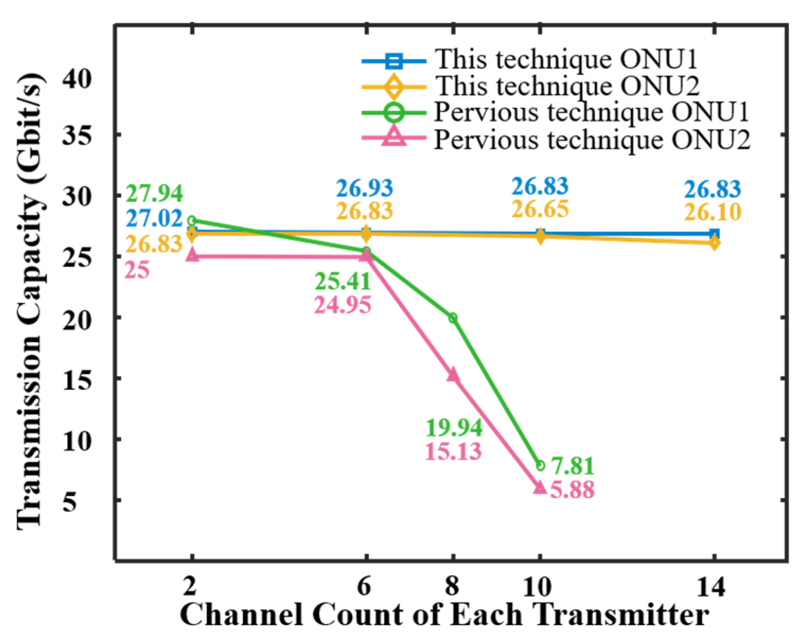
Based on the experimental setup described in Section 3.1, this section experimentally evaluates the impact of channel count variations on the maximum achievable aggregated upstream transmission capacities of the considered two P2MP transceivers. The received optical power is fixed at −5 dBm. The results are presented in Figure 7.
It can be found from Figure 7 that for the previously reported P2MP transceivers, increasing the channel count to >8 leads to a considerable reduction in the maximum achievable aggregated upstream transmission capacity. This agrees with the result in [10]. This is because an increase in channel count leads to more pronounced channel interference [10]. While for the new P2MP transceivers, increasing the channel count to 14 can only cause a <0.7% reduction in the aggregated upstream transmission capacities. This implies that the new P2MP transceivers can support more channels with highly robust transmission performances, as also suggested by the results in Section 4.3.

3.4. Transceiver DSP Complexity Comparison

Based on the theoretical analyses in Section 2.3, the transmitter DSP complexities of the two transceivers were calculated, and the results are presented in Figure 8. Figure 8a shows the multi-channel aggregation DSP complexity only (excluding digital filter DSP complexity). Figure 8b plots the overall transmitter DSP complexity, including both the multi-channel aggregation and digital filter DSP complexities. To highlight the new transceiver’s advantages in considerably reducing the DSP complexity, the DSP complexity ratios between the new transceivers and the previous transceivers are also illustrated in these figures. The up-sampling factor of M is 256, and the PONs are assumed to accommodate 128 ONUs. All other parameters that are not mentioned above are listed in Table 1.
The results in Figure 8a show that as the channel count increases, the superiority of the new P2MP transceivers in reducing the multi-channel aggregation DSP complexity becomes more pronounced. On the other hand, the new transceivers employ EGF-based digital filter banks, which, compared to the previously reported P2MP transceivers’ SRRC filters, can reduce the optimum digital filter length by a factor of 4 [14]. Therefore, as shown in Figure 8b, the new P2MP transceivers can reduce the overall transmitter DSP complexity by >75%, which is almost independent of channel count.
It is also worth mentioning that because the receiver multi-channel de-aggregation DSPs are inverse to the transmitter’s counterparts, the new P2MP transceiver-induced reductions in the receiver multi-channel de-aggregation DSP complexity are similar to those in Figure 8a.

4. Experimental Demonstrations of Concurrent Direct Inter-ONU and Upstream Communication IMDD PONs

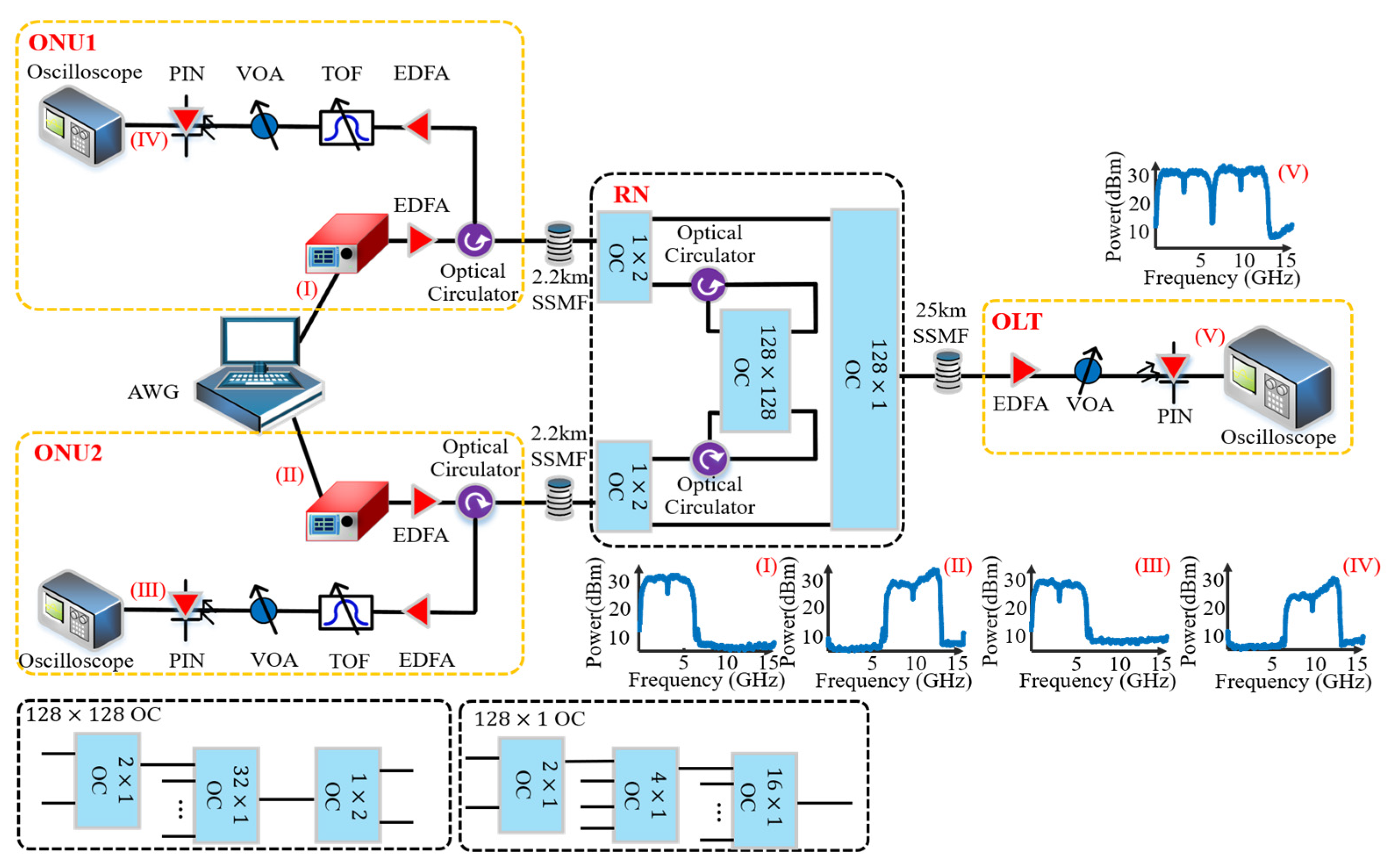
To experimentally evaluate the concurrent direct inter-ONU and upstream communication IMDD PON incorporating the new P2MP transceivers and the modified RNs, in this section, a 27 km, >54.31 Gbit/s upstream IMDD PON is considered, as shown in Figure 9. As shown in the figure, the RN is constructed by 128-port OCs, suggesting that the PON can accommodate 128 ONUs. Due to the lack of key experimental devices, for simplicity, these 128-port OCs are constructed using multiple OCs. For the experimental setup, the ONU optical launch power is 6.6 dBm, while all other key experiment parameters, including the AWG/oscilloscope sampling speed and the MZM/laser/EGF filter parameters, are similar to those listed in Table 1.

4.1. Experimental Setups and Parameters

A dual-channel AWG is used to produce two ONU signals, each containing six independent channels (three for upstream communications and three for inter-ONU communications). In each ONU’s transmitter DSP, for simplicity, the A and B signals are used for the upstream and inter-ONU communications, respectively, and they employ similar subcarrier allocations. Among the overall 31 subcarriers, 15 subcarriers are allocated for a single channel (CH1), and the remaining 16 subcarriers are used for conveying two channels (CH2 and CH3, with eight input samples per channel, aggregated via a 16-point IFFT operation).
After multi-channel aggregation, similar to that mentioned in Section 3.1, the following transmitter DSP procedure is adopted, which includes an EGF-based orthogonal digital filtering operation, a 1.2× digital oversampling operation, an ONU timing adjustment operation, and a signal clipping operation. The resulting channel bitrates, the ONU bitrates, and the aggregated overall transmission bitrates, are summarized in Table 4.
The OLT’s upstream communication receiver and the ONU’s inter-ONU communication receivers have similar configurations and DSP procedures, apart from the fact that each ONU receiver employs an extra TOF to remove unwanted wavelengths (i.e., its upstream wavelength). The receiver DSP procedure includes sampling adjustments, S/P conversions, CP removals, a 256-point FFT operation, subcarrier equalizations, parallel multi-channel de-aggregations, and m-QAM decoding. In addition, the AWG-embedded pre-compensation functions are also used to flatten the upstream communication frequency response of the considered PONs.
For the considered experimental setups, the modified RN introduces ~28 dB optical power losses for the upstream signals and ~34 dB power losses for the inter-ONU communication signals. The measured inter-ONU signal power losses are slightly larger than the corresponding theoretically estimated value of 32.65 dB, as mentioned in Section 2.1, due to the cascading connections of multiple OCs (required for constructing the 128-port OC) and the used optical circulators. On the other hand, when the considered 128-port OCs is used to construct the RNs of the conventional inter-ONU communication PONs [11,12,13], the resulting inter-ONU signal power losses are ~52 dB (inter-ONU signals pass a 128-port OC twice), which also agree with the theoretically estimated value of 49.3 dB in [9]. As such, the experimental results confirm the validity of both the RN power loss analyses in Section 2.1 and the superiority of the modified RNs over the conventional OC-based inter-ONU PON RN designs [11,12,13] in reducing inter-ONU signal power losses.

4.2. Upstream and Direct Inter-ONU Communication Transmission Performances

Considering the above experimental setup and parameters, the BER performances of the concurrent upstream and inter-ONU communications are presented in Figure 10, where adaptive bit-loading is used to ensure that the two ONUs have similar upstream and inter-ONU transmission performances.
As shown in Table 4, for each ONU, the upstream channels conveyed by the A signal and the inter-ONU channels conveyed by the B signal have similar transmission bitrates. However, in comparison with the upstream channels, the inter-ONU channels exhibit ~6 dB receiver sensitivity improvements; this is due to the reduced fiber transmission distance-induced effective mitigations in the channel fading effect. This implies that the demonstrated PONs are promising for offering high transmission capacity and low-latency direct inter-ONU communication services for end-users within the same PONs.
When the received optical powers are >−8 dBm, the inter-ONU channels show BER floors. This is because the pre-compensation operation for flattening upstream communication frequency responses, as mentioned in Section 4.1, causes unwanted inter-ONU signal distortions, as verified by the electrical signal spectra shown in Figure 9(IV), where the ONU1-received inter-ONU signal spectrum is not flat. This can be effectively mitigated using post-compensation techniques, where the receivers adapt their embedded equalizers according to the actual distortions of their received signals.
In addition, for the considered experimental setups, the inter-ONU signals experience negligible Rayleigh and Brillouin backscattering effects because (1) the backscattered optical noises produced by the distribution fibers, i.e., fibers between each ONU and the RN, are removed by the TOF used in each ONU, and (2) the RN introduces a large power loss for the backscattered optical noises produced by the feeder fibers, i.e., fibers between the RN and the OLT. This statement is verified by Figure 9(III), where the Brillouin backscattering effect-produced power peak is invisible at ~10.8 GHz [9].
The upstream signals also experience negligible Rayleigh and Brillouin backscattering effects because (1) the RN introduces a large power loss for the backscattered optical noises produced by the distribution fibers and (2) because no downstream signals are transmitted in this experimental setup. For practical applications, the downstream and upstream/inter-ONU signals can utilize different wavelengths to mitigate the effects of Rayleigh and Brillouin backscattering.

4.3. Flexible Variations in Upstream and Inter-ONU Communication Channel Count

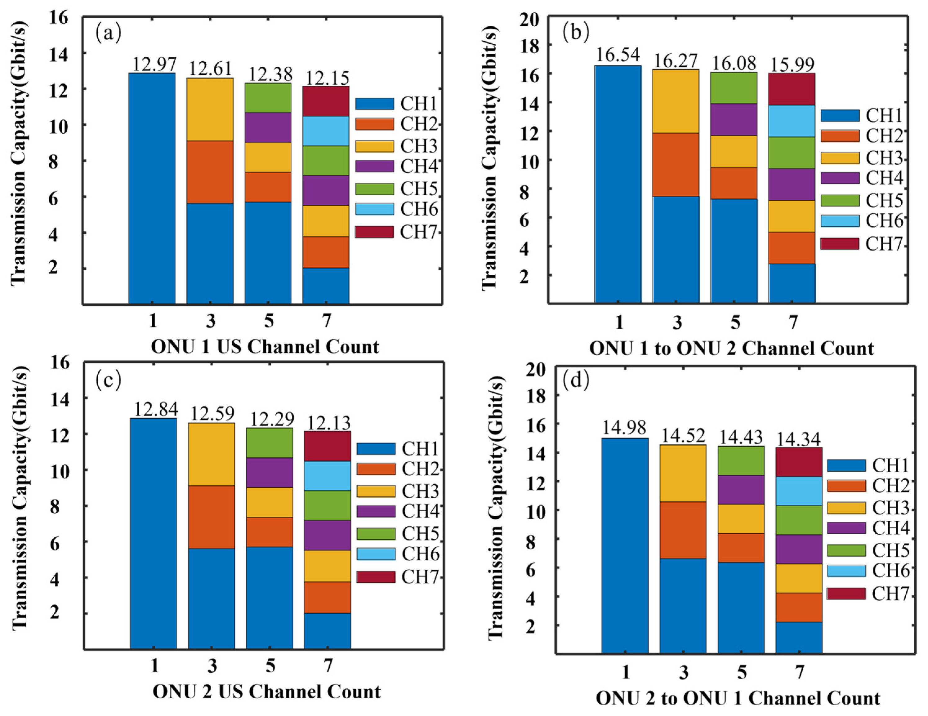
Utilizing the experimental setup presented in Section 4.1, the impact of upstream and inter-ONU channel count variations on maximum achievable upstream and inter-ONU transmission capacities was evaluated, and the results are presented in Figure 11. The received optical power for the upstream (inter-ONU) communications is fixed at −2 dBm (−7 dBm). In the figure, for each considered channel count of N (N = 1, 3, 5, and 7), the A and B signals of each ONU are used to convey N upstream channels and N independent inter-ONU channels, respectively.
It can be found that increasing each ONU’s inter-ONU and upstream channel count from 1 to 7 just slightly reduces its achievable upstream and inter-ONU transmission capacities by <6.4%. This indicates that the proposed PONs allow each ONU to flexibly change its upstream and inter-ONU channel count without significantly compromising its achievable transmission capacities.
Considering a standard 128-port OC with a typical loss uniformity of 2.8 dB, the modified RNs can introduce ~2.8 dB power loss differences for different ONU signals (for both the inter-ONU signals and the upstream signals). The ONUs experiencing relatively large power losses suffer from the degraded transmission performance. As such, ONU power equalization techniques [26] can be practically applied to reduce the received optical power differences between different ONUs.
For the demonstrated PONs, the inter-ONU and upstream communications employ a set of wavelengths, and each ONU’s inter-ONU and upstream data is modulated on its allocated wavelength. The downstream communication can use different wavelengths to reduce unwanted interferences between inter-ONU, downstream, and upstream communications.

5. Conclusions

This paper has experimentally demonstrated a novel concurrent direct inter-ONU and upstream communication IMDD PON, redesigning the P2MP optical transceiver DSPs. Compared to the previously reported P2MP transceiver DSP designs, the new design can not only lead to a >75% (>40%) reduction in the overall transmitter (the receiver multi-channel de-aggregation) DSP complexity but also enhance the demonstrated PON’s capability of providing on-demand ultra-dense connections.
Detailed experimental evaluations of the demonstrated PONs were undertaken using a 27 km, >54.31 Gbit/s upstream IMDD PON, whose RN was constructed by 128-port OCs capable of supporting 128 ONUs. The experimental results indicate that the PONs allow each ONU to flexibly change their upstream and inter-ONU channel counts without considerably compromising their achievable inter-ONU and upstream transmission capacities.
Overall, the demonstrated PONs outperform those of previously reported works in terms of ensuring low DSP complexity, highly robust transmission performance, and an enhanced capacity to flexibly accommodate numerous applications with diverse requirements.
The real-time implementation of the new transceivers, as well as their implementation in concurrent inter-ONU and upstream communication IMDD PONs, is currently being undertaken in our labs, and the corresponding results will be published in due course.
Author Contributions

Conceptualization, W.J., L.C. and H.Y.; methodology, Y.H. and J.T.; software, R.P.G. and J.H.; validation, L.C. and W.J.; formal analysis, M.S.F. and X.Y.; investigation, H.Y. and S.J.; data curation, L.C.; writing—original draft, W.J.; writing—review and editing, L.C. All authors have read and agreed to the published version of the manuscript.

Funding

This work was part-funded by International Science and Technology Cooperation Program of Sichuan Province (2023YFH0067); part-funded by the UK Research and Innovation (UKRI), Engineering and Physical Sciences Research Council (EPSRC) (Project TITAN, [EP/Y037243/1]); part-funded by the UK Research and Innovation (UKRI), Engineering and Physical Sciences Research Council (EPSRC) (Project HASC, [EP/Y037197/1/ EP/X040569/1]); part-funded by the Welsh Government and the UK Government (North Wales Growth Deal through Ambition North Wales); part-funded by the Science and Technology Commission of Shanghai Municipality Project (SKLSFO2021-02, SKLSFO2022-04); and part-funded by the National Natural Science Foundation of China (NSFC) (62475144).

Data Availability Statement

Data are contained within the article.

Conflicts of Interest

The authors declare no conflicts of interest.

Appendix A

Table A1. Comparison of techniques of concurrent Inter-ONU and upstream communication IMDD PONs incorporating OC-based RNs and different optical transceivers.
Ref.Technique SolutionAdvantages and Disadvantages
This work
  • P2MP transceivers using a parallel channel aggregation/de-aggregation operation and advanced extended Gaussian function (EGF)-based rectangular orthogonal digital filters.
  • An optical coupler-based modified RN design with significantly low inter-ONU power losses [9].
  • Conventional tree-topology PON architectures.
  • Frequency division multiplexing (FDM) PONs.
  • Different ONUs using different wavelengths.
  • Lowest transmitter DSP complexity, compared to existing P2MP transceiver-based solutions [9,12,13]. Compared to [9,10], it leads to >75% (>40%) reductions in the overall transmitter (receiver multi-channel de-aggregation) DSP complexity.
  • First experimental demonstration and evaluation of a modified RN architecture having a significantly low inter-ONU signal power loss (~32.65 dB) in an environment capable of supporting 128 ONUs.
  • No need to use tunable lasers at ONUs to lock the ONU laser frequency.
  • Effective reductions in high latency and time jitter issues.
  • Additional physical layer network security due to multi-channel aggregations in both the time domain and the frequency domain [10].
[9]
  • P2MP transceivers using a cascaded IFFT/FFT-based multi-channel aggregation/de-aggregation operation and conventional square-root-raised-cosine (SRRC)-based rectangular orthogonal digital filters.
  • Two optical coupler-based modified RN designs proposed and theoretically analyzed (without experimental verifications and evaluations).
  • Conventional tree-topology PON architectures.
  • FDM PONs.
  • Different ONUs using different wavelengths.
  • Transmitter DSP complexity is lower than that reported in [12,13], but higher than in this work. Compared to [12,13], it can reduce the transmitter multi-channel aggregation DSP complexity by a factor that is approximately equal to the aggregated channel count [10].
  • Non-negligible channel interference effect when the channel count is large.
  • Experimental demonstrations still use 3-by-N optical couplers, leading to an unacceptable inter-ONU signal power loss of 49.3 dB for cases where 128 ONUs are accommodated.
  • No need to use tunable lasers at ONUs to lock the ONU laser frequency.
  • Effective reductions in high latency and time jitter issues.
  • Additional physical layer network security due to multi-channel aggregations in both the time domain and the frequency domain [10].
[12,13]
  • P2MP transceivers using SRRC-based rectangular orthogonal digital filter banks for multi-channel aggregation.
  • 3-by-N optical couple-based modified RNs.
  • Conventional tree-topology PON architectures.
  • FDM PONs.
  • Different ONUs using different wavelengths.
  • Highest transmitter DSP complexity, compared to [9] and this work.
  • RNs having unacceptable inter-ONU signal power losses of 49.3 dB for cases where 128 ONUs are accommodated.
  • No need to use tunable lasers at ONUs to lock the ONU laser frequency.
  • Effective reductions in high latency and time jitter issues.
[11]
  • NG-PON2 transceivers.
  • Time- and wavelength-division multiplexing (TWDM) PONs.
  • 3-by-N optical couple-based modified RNs.
  • Extra wavelengths for inter-ONU communication.
  • Tunable lasers used in ONU transmitters.
  • RNs having unacceptable inter-ONU signal power losses of 49.3 dB for cases where 128 ONUs are accommodated.
[15,16]
  • Virtualized mesh-PONs.
  • Time- and wavelength-division multiplexing (TWDM) PONs.
  • Optical coupler-based two-stage RNs.
  • Wavelength reflectors such as reconfigurable fiber Bragg gratings (FBGs) used at RNs for achieving inter-ONU communications.
  • Tunable lasers used in ONU transmitters.
  • Optical amplifiers used at RNs to compensate for the inter-ONU signal power loss.
  • Compared to tree-topology PON solutions, considerable network architecture modification required for widely deployed tree-topology PONs.
[17]
  • Pulse-amplitude modulation (PAM)-based transceivers.
  • Allowing two ONUs to communicate with each other by multiplexing two ONUs’ optical signals in the optical domain and demultiplexing them in the electrical or digital domains (subtraction operations).
  • N-by-N optical couple-based modified RNs.
  • Incapable of supporting simultaneous inter-ONU communications among more than two ONUs without using extra techniques such as TDM.
  • RNs having unacceptable inter-ONU signal power losses of 49.3 dB for cases where 128 ONUs are accommodated.
  • Accurate ONU timing control required to ensure that the unwanted signals are removed in the demultiplexing process to reduce the channel interference effects.

References

  1. ITU-R. Framework and Overall Objectives of the Future Development of IMT for 2030 and Beyond; International Telecommunication Union: Geneva, Switzerland, 2023. [Google Scholar]
  2. ITU-T G.8300; Characteristics of Transport Networks to Support IMT-2020/5G. International Telecommunication Union: Geneva, Switzerland, 2020.
  3. Chen, J.; Liang, X.; Xue, J.; Sun, Y.; Sun, H.; Shen, X. Evolution of RAN architectures toward 6G: Motivation, development, and enabling technologies. IEEE Commun. Surv. Tutor. 2024, 26, 1950–1988. [Google Scholar] [CrossRef]
  4. Saliou, F.; Simon, G.; Huérou, S.L.; Chanclou, P.; Potet, J.; Gaillard, G.; Percevault, U.; Chevalier, D.; Zandueta, J.; Yang, B.; et al. Coexistence in future optical access networks from an operator’s perspective [Invited]. J. Opt. Commun. Netw. 2024, 16, A78–A88. [Google Scholar] [CrossRef]
  5. Fayad, A.; Cinkler, T.; Rak, J. 5G/6G optical fronthaul modeling: Cost and energy consumption assessment. J. Opt. Commun. Netw. 2023, 15, D33–D46. [Google Scholar] [CrossRef]
  6. Pfeiffer, T.; Dom, P.; Bidkar, S.; Fredricx, F.; Christodoulopoulos, K.; Bonk, R. PON going beyond FTTH [Invited Tutorial]. J. Opt. Commun. Netw. 2022, 14, A31–A40. [Google Scholar] [CrossRef]
  7. Pfeiffer, T. Considerations on transport latency in passive optical networks. In Proceedings of the 45th European Conference on Optical Communication (ECOC 2019), Dublin, Ireland, 22–26 September 2019. [Google Scholar]
  8. Saliou, F.; Chanclou, P.; Simon, G.; Potet, J.; Gaillard, G.; Zandueta, J.; Chevalier, D. Optical access networks to support future 5G and 6G mobile networks [Invited]. J. Opt. Commun. Netw. 2025, 17, C22–C29. [Google Scholar] [CrossRef]
  9. Jin, W.; Chen, L.; He, J.; Giddings, R.P.; Huang, Y.; Hao, M.; Faruk, M.S.; Yi, X.; Wang, T.; Tang, J. Concurrent direct inter-ONU and upstream communications in IMDD PONs incorporating P2MP flexible optical transceivers and advanced passive remote nodes. Photonics 2024, 11, 1021. [Google Scholar] [CrossRef]
  10. Chen, L.; Jin, W.; He, J.X.; Giddings, R.P.; Huang, Y.; Tang, J.M. A point-to-multipoint flexible transceiver for inherently hub-and-spoke IMDD optical access networks. J. Light. Technol. 2023, 41, 4743–4754. [Google Scholar] [CrossRef]
  11. Hwang, I.-S.; Rianto, A.; Kharga, R.; Ab-Rahman, M.S. Global P2P BitTorrent real-time traffic over SDN-based local-aware NG-PON2. IEEE Access 2022, 10, 76884–76894. [Google Scholar] [CrossRef]
  12. Zhong, Z.; Jin, W.; Jiang, S.; He, J.X.; Chang, D.; Giddings, R.P.; Hong, Y.H.; O’Sullivan, M.; Durrant, T.; Mariani, G.; et al. Experimental demonstrations of concurrent adaptive inter-ONU and upstream communications in IMDD hybrid SSB OFDMDFMA PONs. In Proceedings of the 2021 Optical Fiber Communications Conference and Exhibition (OFC), San Francisco, CA, USA, 6–10 June 2021. [Google Scholar]
  13. Zhong, Z.Q.; Jin, W.; Jiang, S.; He, J.X.; Chang, D.; Hong, Y.H.; Giddings, R.P.; Jin, X.Q.; O’Sullivan, M.; Durrant, T.; et al. Concurrent inter-ONU communications for next generation mobile fronthauls based on IMDD hybrid SSB OFDM-DFMA PONs. J. Light. Technol. 2021, 39, 7360–7369. [Google Scholar] [CrossRef]
  14. Jin, W.; Zhong, Z.Q.; Shan, S.; He, J.X.; Chang, D.; Hong, Y.H.; Giddings, R.P.; Jin, X.Q.; O’Sullivan, M.; Durrant, T.; et al. Rectangular orthogonal digital filter banks based on extended Gaussian functions. J. Light. Technol. 2022, 40, 3709–3722. [Google Scholar] [CrossRef]
  15. Das, S.; Slyne, F.; Ruffini, M. Optimal slicing of virtualized passive optical networks to support dense deployment of cloud-ran and multi-access edge computing. IEEE Netw. 2022, 36, 131–138. [Google Scholar] [CrossRef]
  16. Das, S.; Slyne, F.; Kilper, D.; Ruffini, M. Two-tier PON virtualization with scheduler synchronization supporting application-level ultra-low latency in MEC based cloud-RAN, using MESH-PON. J. Opt. Commun. Netw. 2023, 15, C100–C107. [Google Scholar] [CrossRef]
  17. Lu, Y.; Deng, H.; Hu, L.; Cao, L.; Luo, Y.; Wang, J.; Zhai, Y. Inter-ONU-communication for future PON based on PAM4 physical-layer network coding. Opt. Commun. 2021, 497, 127162. [Google Scholar] [CrossRef]
  18. Zhao, Q.; Chan, C.-K. A wavelength-division-multiplexed passive optical network with flexible optical network unit internetworking capability. J. Light. Technol. 2007, 25, 1970–1977. [Google Scholar] [CrossRef]
  19. Li, Y.; Wang, J.; Qiao, C.; Gumaste, A.; Xu, Y.; Xu, Y. Integrated fiber-wireless (FiWi) access networks supporting inter-ONU communications. J. Light. Technol. 2010, 28, 714–724. [Google Scholar]
  20. Yin, S.; Shen, T.S.; Bi, Y.; Jin, J.; Oyama, T.; Kazovsky, L.G. A novel quasi-passive, software-defined, and energy efficient optical access network for adaptive intra-PON flow transmission. J. Light. Technol. 2015, 33, 4536–4546. [Google Scholar] [CrossRef]
  21. Li, X.; Gan, C.; Yan, Y.; Qiao, H. Grid architecture of a metro-access optical network to support discretionary peer-to-peer intracommunication and intercommunication between ONUs. J. Opt. Commun. Netw. 2019, 11, 130–139. [Google Scholar] [CrossRef]
  22. Garg, A.K.; Janyani, V.; Aly, M.H.; Abidin, N.Z.; Kamil, Y.M.; Radhouene, M. Flexible energy-efficient and direct intra-ODN/OPN communication capable TWDM PON architecture with centralized OLT sharing among multiple optical networks. Opt. Fiber Technol. 2022, 72, 102999. [Google Scholar] [CrossRef]
  23. Ahmed, S.; Butt, R.A.; Aslam, M.I. Simultaneous upstream and inter optical network unit communication for long reach PON using single transmitter and self-phase modulation. Opt. Fiber Technol. 2024, 82, 103639. [Google Scholar] [CrossRef]
  24. Mahdavi, M. Reordering-less FFT: A novel FFT processor with parallel input/output in normal order. In Proceedings of the 2023 International Conference on Software, Telecommunications and Computer Networks (SoftCOM), Split, Croatia, 21–23 September 2023; pp. 1–6. [Google Scholar]
  25. Al-Rawachy, E.; Giddings, R.P.; Tang, J. Experimental demonstration of a real-time digital filter multiple access PON with low complexity DSP-based interference cancellation. J. Light. Technol. 2019, 37, 4315–4329. [Google Scholar] [CrossRef]
  26. Park, Y.; Lim, C.; Jung, I. ONU power equalization of Ethernet PON systems. IEEE Photon. Technol. Lett. 2004, 16, 1984–1986. [Google Scholar] [CrossRef]
Figure 1. Schematic diagram of the concurrent direct inter-ONU and upstream communication IMDD PONs. Yellow arrows: inter-ONU and upstream optical signals. Blue arrows: downstream optical signals.
Photonics 12 00838 g001
Figure 2. Modified RN architecture capable of accommodating N ONUs. OC: optical coupler. Yellow arrows: inter-ONU and upstream optical signals. Blue arrows: downstream optical signals.
Photonics 12 00838 g002
Figure 3. DSP-enabled multi-channel aggregation.
Photonics 12 00838 g003
Figure 4. DSP-enabled multi-channel de-aggregation.
Photonics 12 00838 g004
Figure 5. Experimental setup of a 25 km, >53.9 Gbit/s IMDD upstream PON for comparing the performances between the new transceiver and the previously reported transceivers.
Photonics 12 00838 g005
Figure 6. Upstream transmission performance comparisons. (ad) for BER performances of ONU1 A signal, ONU1 B signal, ONU2 A signal, and ONU2 B signal, respectively. Dashed black lines represent the BER performances of the previously reported P2MP transceivers.
Photonics 12 00838 g006
Figure 7. Channel count-dependent upstream transmission capacity comparisons.
Photonics 12 00838 g007
Figure 8. (a) Transmitter multi-channel aggregation DSP complexity (excluding digital filter DSP complexity); (b) overall transmitter DSP complexity, including both multi-channel aggregation and digital filter DSP complexities.
Photonics 12 00838 g008
Figure 9. Experimental setup of a 27 km, >54.31 Gbit/s upstream IMDD PON for evaluating the proposed concurrent direct inter-ONU and upstream communication techniques. (I)~(V): electrical signal spectra.
Photonics 12 00838 g009
Figure 10. Transmission performances for (a) upstream (US) and (b) inter-ONU communications.
Photonics 12 00838 g010
Figure 11. Channel count variation-induced impacts on (a) ONU1’s achievable upstream transmission capacities, (b) ONU1’s achievable inter-ONU transmission capacities, (c) ONU2’s achievable upstream transmission capacities, and (d) ONU2’s achievable inter-ONU transmission capacities.
Photonics 12 00838 g011
Table 1. Key experimental setup parameters.
ParameterValueParameterValue
Modulation formatsm-QAMLaser linewidth10 kHz
Cyclic prefix ratio12.5%SSMF length25 km
Up-sampling factor (M)4ONU1 wavelength1564.6 nm
Clipping ratio11 dBONU2 wavelength1565.4 nm
SRRC roll-off coefficient0ONU optical launch power5 dBm
SRRC digital filter length32Tunable optical filter bandwidth0.8 nm
EGF filter coefficientsα = 0.23, υ = 0.9, τ = 1PIN bandwidth40 GHz
EGF digital filter length8Oscilloscope ADC sampling speed64 GS/s
AWG DAC sampling speed30 GS/sOscilloscope ADC resolution10-bit
AWG DAC resolution8-bitOscilloscope bandwidth59 GHz
Each ONU signal bandwidth6.25 GHzMZM bandwidth35 GHz
Each ONU signal amplitude350 mV
Table 2. Upstream transmission bitrates of new P2MP transceivers (Gbit/s).
CH1CH2CH3CH4CH5CH6CH7ONU BitrateTotal
ONU1A signal2.221.991.991.871.871.871.8727.3654.1
B signal2.221.991.991.871.871.871.87
ONU2A signal2.221.961.961.851.851.751.7526.68
B signal2.221.961.961.851.851.751.75
Table 3. Upstream transmission bitrates of previously reported P2MP transceivers (Gbit/s).
CH1CH2CH3CH4ONU BitrateTotal
ONU13.43.46.614.127.554.3
ONU23.43.46.213.826.8
Table 4. Upstream transmission bitrates (Gbit/s).
CH1CH2CH3ONU BitrateTotal
ONU1A Signal (upstream)5.513.403.4024.6254.31
B Signal (inter-ONU)5.513.403.40
ONU2A Signal (upstream)6.994.324.3229.69
B Signal (inter-ONU)6.343.863.86
Disclaimer/Publisher’s Note: The statements, opinions and data contained in all publications are solely those of the individual author(s) and contributor(s) and not of MDPI and/or the editor(s). MDPI and/or the editor(s) disclaim responsibility for any injury to people or property resulting from any ideas, methods, instructions or products referred to in the content.