Review

Photonic Integrated Circuits: Research Advances and Challenges in Interconnection and Packaging Technologies

1
State Key Laboratory of Electromechanical Integrated Manufacturing of High-Performance Electronic Equipments, Xidian University, Xi’an 710071, China
2
School of Electro-Mechanical Engineering, Xidian University, Xi’an 710071, China
*
Author to whom correspondence should be addressed.
Photonics 2025, 12(8), 821; https://doi.org/10.3390/photonics12080821
Submission received: 16 July 2025 / Revised: 12 August 2025 / Accepted: 14 August 2025 / Published: 18 August 2025
(This article belongs to the Special Issue Photonic Integrated Circuits: Recent Advances and Future Perspectives)

Abstract

Silicon photonics, serving as a cornerstone technology in modern information technology, demonstrates significant application potential in critical scenarios such as high-speed data center interconnects and integrated optical communication systems. Facing the persistent demand for information processing capabilities in the post-Moore era, photonic chips have emerged as a pivotal direction for overcoming the performance bottlenecks of traditional chips, leveraging their advantages of low power consumption, high speed, and high integration density. This review focuses specifically on the optical interconnection and packaging technologies for photonic chips. It comprehensively analyzes the research frontiers and key challenges in packaging technologies, encompassing efficient fiber-to-chip coupling techniques, chip-scale optical interconnection technologies, and 2D, 2.5D, and 3D stacked co-packaged optics technologies. By synthesizing and summarizing recent research advances, this paper aims to provide researchers in related fields with a systematic understanding of photonic integrated circuit technology. Furthermore, it seeks to offer insights for future technological breakthroughs in device optimization, packaging innovation, and system-level applications of photonic integrated circuits.

1. Introduction

Since the proposal of Moore’s Law, integrated circuits have achieved exponential growth in computing power through the scaling down of transistor dimensions and the increase in transistor density. However, as transistor feature sizes enter the sub-10-nanometer regime, quantum tunneling effects lead to exacerbated leakage currents and degraded transistor switching efficiency, posing severe challenges to power consumption and reliability. In the field of artificial intelligence, high-performance computing systems exemplified by AlphaGo exhibit power consumption as high as 200 kW, significantly exceeding the human brain’s 20 W. This stark contrast highlights the substantial room for improvement within traditional electrical signal processing architectures regarding power reduction and performance enhancement [1,2,3,4]. Driven by the advancement of artificial intelligence, 6G communications, and quantum computing, the demand for high-performance, low-power information-processing technologies is rapidly growing. Leveraging advantages such as high bandwidth, low energy consumption, and strong parallelism, Photonic Integrated Circuits (ICs) have emerged as a pivotal approach to overcoming the bottlenecks of electronic chips. PICs integrate optoelectronic devices, including lasers, modulators (such as Mach–Zehnder Modulators and Ring Resonator Modulators), detectors, and waveguides, onto a single chip using silicon photonic integration technology [4]. PICs employ photons as information carriers, utilizing multi-dimensional attributes of light (e.g., wavelength, amplitude, and phase) for signal transmission and processing. Despite challenges like heterogeneous material-integration processes and device packaging, their breakthrough applications in fields such as neural network computing, Optical Phased Arrays (OPAs), and programmable optical computing have already demonstrated significant potential. Looking ahead, with the in-depth integration of silicon photonics technology and Complementary Metal-Oxide-Semiconductor (CMOS) technology, as well as the development of high-performance photonic devices based on hybrid platforms such as silicon-on-insulator (SOI), III–V, silicon nitride (SiN) [5], and lithium niobate-on-insulator (LNOI)—including microresonators with Euler bends [6]—PICs are expected to drive the transition of information processing from “electrically driven” to “optically dominated”. This will provide a novel pathway for the computing power revolution in the post-Moore era.
A Photonic Integrated Circuit is a technology that integrates optoelectronic components to realize optical signal processing and communication functions. Its structure mainly comprises three parts: first, discrete components as basic units, such as high-power, high-frequency distributed feedback (DFB) lasers [7], quantum-dot light-source lasers [8] (for generating optical signals), high-bandwidth, high-speed modulators [9,10] (for encoding information onto optical signals), 2D-material-based photodetectors [11,12,13] (for converting optical signals to electrical signals), and all-optical encoders [14], among others; second, an efficient-transmission optical interconnection system formed by achieving optical path connections between components through fiber coupling technology and new photon bonding technology; third, a co-packaged structure formed by co-packaging silicon-based PICs with application-specific integrated circuits (ASICs). This structure combines the advantages of PICs in optical signal processing with the data processing and control capabilities of ASICs, and can be applied in fields such as communications, phased arrays, neural network computing, and programmable PICs, thereby expanding the application scope of PICs.
IBM’s former No. 1 supercomputer ROADRUNNER, introduced in 2008, was the first petaflop system. In ROADRUNNER, photonics was used exclusively at the card edge, see Figure 1a. Three years later, IBM launched the POWER 775 supercomputer. In the POWER 775 system, photonics was brought onto the board. For the first time in a system of that scale, the optical transceivers were assembled into the ASIC package. On each carrier substrate, 56 optical transceiver modules were assembled and connected to the board edge by multi-mode (MM) optical-fiber ribbons, see Figure 1b. In the largest POWER 775 system, about one million fibers were required. From an assembly, routing, and cost perspective, this huge number of discrete photonic components is a challenge. In electrical systems, discrete components and electrical wires have been replaced by integrated circuits and PCB technology. We believe that optical technologies will have to follow a similar path. To massively improve the density of the interconnects in order to minimize the assembly overhead and related costs, a radically different approach is currently proposed in which the Si photonic chip is integrated directly on the carrier substrate together with the ASIC chip to realize co-packaged optics (CPO) [15], as shown in Figure 1c. Among them, edge or grating coupling technologies are used between fibers and waveguides, and photonic bonding technologies are used for high-density interconnection between Si photonic chips, as shown in Figure 1c.
This paper mainly focuses on the packaging technologies of PICs. Section 2 will introduce the applications of PICs; Section 3 will elaborate on optical interconnection technologies, including packaging technologies for coupling between optical fibers and on-chip waveguides as well as on-chip photonic wire bond (PWB) technologies; Section 4 will present the co-packaging technology of optical chips and electronic chips; Section 5 will discuss the challenges in photonic chip packaging, covering optical interconnection, CPO, thermal management, and packaging design rules for optical chips.

2. The Application of PIC

2.1. Neural Network Computing

Electronic neural networks based on the von Neumann architecture are limited by the “memory wall” problem, with most of the energy consumption being used for data transfer rather than calculation [16]. Photonic neural networks unify data storage and computing units at the physical level through an analog computing architecture, and utilize the parallel propagation of light to achieve light–speed calculation of vector–matrix multiplication. For example, Tait et al. designed a silicon photonic neural network that accelerated the solving of differential equations in a 24-node network by 294 times [17]. Zhu et al. developed an integrated diffractive neural network (IDNN) chip. This chip achieved an accuracy rate of 89.3% when identifying the Mixed National Institute of Standards and Technology database (MNIST) dataset, while its area was only 1/10 of the traditional solution, and its power consumption was reduced to 1/200 [18]. The Optical AI Team at MIT achieved a new design from devices to chip architectures. They simulated cellular neural networks with laser arrays and developed a new optical chip architecture, achieving a breakthrough in overall performance. For the first time, the advantages of optical computing chips over electronic computing were realized, with a 100-fold improvement in energy efficiency and a 20-fold increase in computing density, and it is expected to achieve improvements of several orders of magnitude in the near future [19].

2.2. Optical Phased Array

The Optical Phased Array (OPA) is a crucial application of PIC in free-space optical communication and LiDAR. Traditional mechanical scanning or MEMS phased arrays have defects such as a large volume and slow response [20]. In contrast, PIC-based OPAs can achieve low-power consumption and high-speed steering by integrating thousands of phase shifters and waveguide antennas. For example, the Ashtian team proposed a novel N × N optical phased array architecture, realizing 2D beam steering with 2N phase shifters outside the aperture instead of the traditional N2 phase shifters [21]. The Technical University of Denmark team achieved 2D beam steering with a 180° alias-free field of view and low sidelobes based on a silicon photonic platform [22].

2.3. Programmable Photonic Integrated Circuit

The Programmable PIC is a type of photonic chip that can achieve multiple functions through software configuration. Its core design concept is derived from Programmable Electronic Integrated Circuits, aiming to solve the problems of fixed functions, long development cycles, and high costs of traditional customized application-specific photonic integrated circuits (ASPICs). This type of chip can dynamically adjust the on-chip optical waveguide network through electrical or temperature control technologies, realizing optical path reconfiguration and function multiplexing. This significantly reduces engineering costs and shortens the product development cycle. The silicon-based programmable processor developed by the Massachusetts Institute of Technology utilizes 56 Mach–Zehnder interferometer (MZI) units to achieve 4 × 4 Special Unitary Group (4) (SU(4)) transformations and neural network computations. It has achieved an accuracy rate of 76.7% in the vowel recognition task, and its power consumption increases linearly with the number of neurons [23]. The programmable diffractive deep neural network (D2NN) architecture based on a digital-coding metasurface array developed by Southeast University in China supports multiple functions such as image classification and communication coding/decoding, providing a universal platform for dynamic optical signal processing [24].

2.4. Biomedical Sensing

Photonic chips, which manipulate light fields at the subwavelength scale through nanostructures and enhance light–matter interactions, play a critical role in biomedical sensing. Leveraging label-free techniques such as surface plasmon resonance and dielectric Mie resonances, they enable highly sensitive detection of low-concentration biomarkers (e.g., cancer-related proteins and DNA/RNA) in biofluids, supporting early diagnosis of infectious diseases, cancer, and other conditions. For example, liquid biopsy, as a non-invasive approach, aids in the rapid identification of early-stage or residual diseases. Integrated with on-chip optoelectronic integration and microfluidic technology, photonic chips promote sensor miniaturization, suitable for continuous bedside monitoring of biomarker or therapeutic drug levels to provide real-time feedback for personalized treatment. Their low cost and ease of use also facilitate the development of wearable devices for personal health monitoring. Furthermore, by combining with data science tools, photonic chips enhance the capability to analyze complex biological samples, demonstrating high-performance advantages in precision medicine, disease diagnosis, and other fields, thus contributing to improved efficiency in medical decision-making and the advancement of personalized healthcare [25].

2.5. Communication in 6G

In the field of 6G communication, PICs exhibit significant application potential in Terahertz (THz) communication technologies. Due to challenges such as atmospheric attenuation and device power limitations in the THz frequency band, photonic solutions are essential to achieve efficient signal generation and detection. For example, THz signals can be generated through photonic heterodyne mixing techniques, and “fiber–THz–fiber” seamless communication systems can be constructed by integrating with optical fiber networks. By utilizing photonic integration technology, it is possible to reduce device coupling losses and system power consumption, thereby enhancing spectral efficiency and transmission rates. These advancements are suitable for scenarios such as high-speed indoor data centers and long-distance inter-satellite communications, facilitating the realization of Tbps-level data transmission and low-power communication goals in 6G. Such progress promotes the practical deployment and application of the THz frequency band in 6G networks [26].

3. Optical Interconnection Technologies

3.1. Fiber-to-Chip Coupling

Over the past two decades, Silicon Photonic Integrated Chip (Si-PIC) technology has profoundly reshaped the development landscape of integrated optics by virtue of its unique advantages in the field of nanoscale optoelectronic device manufacturing. This photonic technology, based on the SOI platform, has laid the foundation for building high-density and low-cost optical information processing systems by reducing the feature size of optoelectronic devices to about one-tenth of that of traditional fiber devices; however, this revolutionary size reduction has also brought about key technical challenges. Optical interconnections between optical fibers and PICs occur frequently in the entire system, and fiber-to-chip optical interconnections are crucial in application scenarios such as data centers and optical transmission systems. So far, the feature size of silicon waveguides can be as small as several tens of nanometers, while the typical diameter of a single-mode fiber (SMF) is about 125 μm, with a core diameter close to 10 μm, as shown in Figure 2a [27]. Figure 2b shows the significant size mismatch between the fiber core and the Si waveguide, which leads to considerable optical transmission loss when light emitted from the fiber core directly enters the Si waveguide. Therefore, appropriate coupling technologies are required to realize optical interconnections between optical fibers and PICs. Optical coupling from fiber to chip mainly falls into two categories: in-plane coupling and out-of-plane coupling, as shown in Figure 2c. Edge couplers (ECs) are used for in-plane coupling, and grating couplers (GCs) belong to out-of-plane coupling. Regardless of the scheme adopted, efficient coupling between optical fibers and chips has always been a core link determining system performance. Given the strategic position of fiber coupling technology in silicon photonic systems, this section will systematically sort out the current mainstream fiber coupler packaging schemes, focusing on analyzing the working principles, performance indicators, and engineering implementation difficulties of different technical paths to provide a comprehensive technical reference for optoelectronic device designers.

3.1.1. Edge Coupler Based on Inverted Spot-Size Converters

Fiber-to-chip edge couplers have been extensively studied by researchers for decades. However, the mode mismatch between optical fibers and PICs leads to significant coupling losses, which may affect the performance of the entire system. To address this issue, researchers proposed using spot-size converters to match the mode field diameter (MFD) of optical fibers and PICs.
Spot-size converters (SSCs) with inverse taper structures play an indispensable role in edge coupling. Corresponding to the direction of light propagation, an inverse taper refers to a tapered waveguide whose width gradually increases along the direction of mode propagation. That is, the narrow end of the taper is close to the optical fiber, while the wide end is connected to the photonic waveguide. An edge coupler with an inverse taper whose narrow tip is aligned with the fiber core can convert the large mode incident from the optical fiber into a compressed guided mode in the photonic waveguide [28]. There is a wide variety of SSC structures used to improve the coupling efficiency of edge couplers, providing a solid foundation for the development of this field.
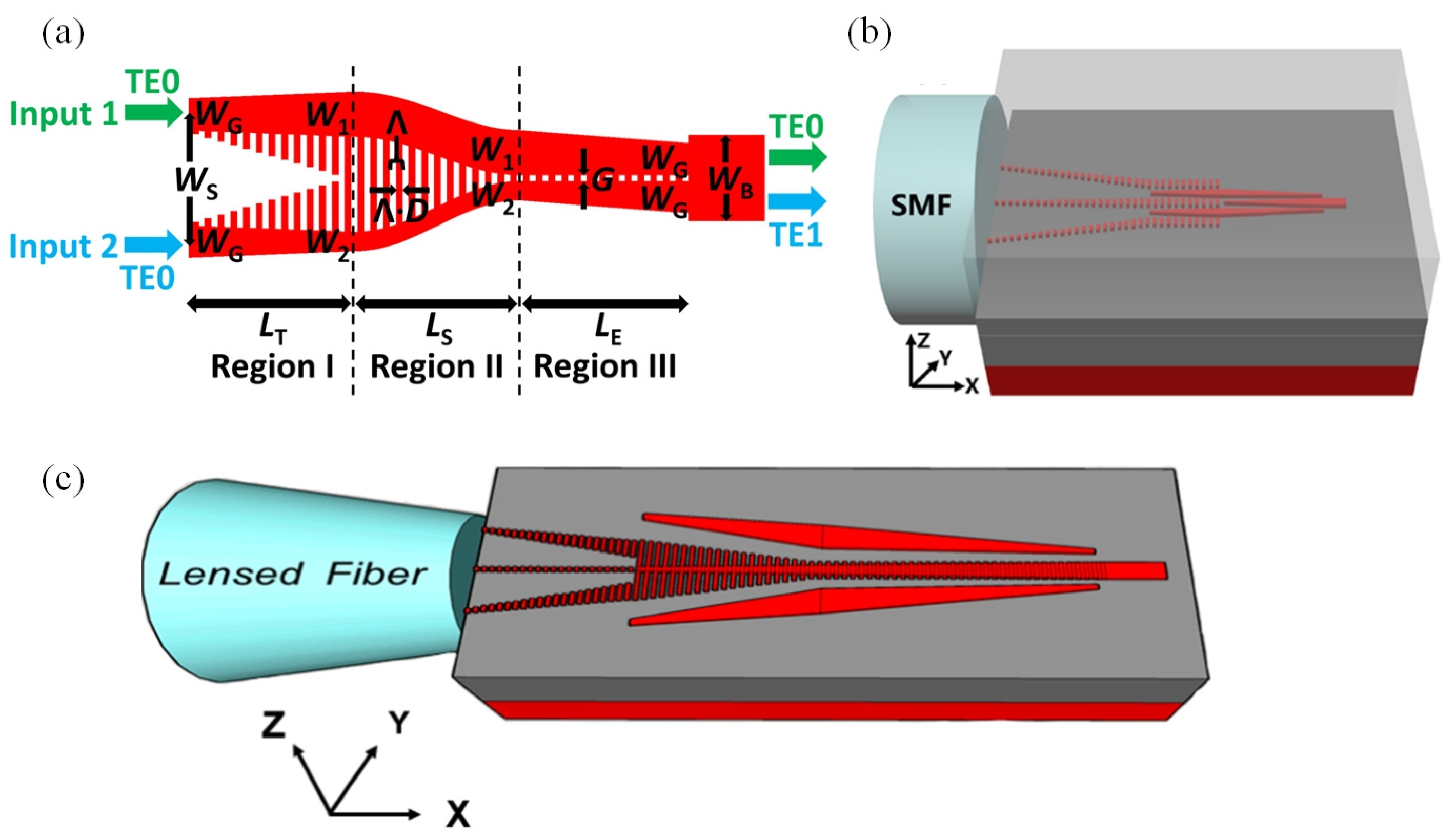
The initial SSCs solely featured three types of inverse-taper mode transformers: linear, exponential, and quadratic. Researchers such as Ren simulated the impact of different parameters—including taper tip width, taper length, and taper gradient line shape function—on the coupling performance between waveguides and optical fibers. The study concluded that while exponential and quadratic inverse tapers have only a slight edge over linear inverse tapers in coupling efficiency, their performance in terms of device size, fabrication tolerance, and misalignment tolerance at the same coupling loss level is significantly superior to that of linear inverse tapers. This offers new ideas for the structural design of subsequent silicon-based photonic devices involving mode transformation [30]. In 2016, Wang et al. proposed an edge coupler (EC) based on double-tip inverse tapers for fiber-to-chip connection. They tested the influence of different tip widths and gaps between the two tips on the coupler loss. It was found that the double-tip structure had a lower coupling loss, higher bandwidth, and higher misalignment tolerance compared with the single-inverse-taper structure [31]. In recent years, with an increasing variety of SSC shapes emerging, the coupling efficiency has been significantly improved. For example, in 2019, Tu et al. proposed a multi-tip EC, as shown in Figure 3a. The multi-tip part of this coupler is composed of multiple inverse-tapered waveguides with equal spacing, with their width and spacing varying linearly, and a coupling efficiency as high as 90.68%. The proposed device is promising for laser-to-chip edge coupling in silicon photonics [32]. In 2021, the Institute of Microelectronics of the Chinese Academy of Sciences innovated the structure of the edge coupler based on multiple cutting-edge technologies. A low-loss edge coupler was fabricated, which consists of a cross-shaped arrangement of five Si3N4 waveguides in three layers surrounded by SiO2 cladding, and also includes curved waveguides and two Si3N4 SSCs, as shown in Figure 3b. This edge coupler can couple the light from a standard SMF-28 fiber with 8.2 μm mode field diameter (MFD) at 1550 nm to a silicon wire waveguide. Through managing the SSCs, the overall coupling efficiency exceeds 90% (0.44 dB) [33]. In 2023, Brunetti proposed that the bare waveguide is a SiO2 fully embedded Si3N4 waveguide. Through simulating the coupling losses of waveguides with different width-to-thickness ratios, it was found that a spot-size converter with a minimum tip aspect ratio of 8:1, a maximum tip aspect ratio of 28:1, and a length of 600 µm ensures a coupling loss of 0.18 dB. This SSC achieved the lowest coupling loss in the C-band [34].

3.1.2. Edge Coupler Based on Subwavelength Grating

Besides the inverse-tapered SSCs, a typical EC also includes the EC based on subwavelength grating (SWG). Xu et al. designed a two-mode multiplexer based on an SWG slot-assisted adiabatic coupler on the SOI platform. This coupler is composed of a linearly tapered region, an S-bend region, and a mode evolution region. The enabling feature of this design is the introduction of an SWG slot to the gap region between two strip waveguides, which effectively increases the refractive index of the gap region and enhances the coupling between two strip waveguides [35]. In 2021, He realized an SWG metamaterial EC, which consists of a width-graded SWG metamaterial section, an SWG strip waveguide section, and a solid taper section, as shown in Figure 4b. This coupler utilizes the SWG structure of the SWG metamaterial to engineer the effective refractive index, and gradually optimizes the huge mode mismatch between the SMF and the chip nanowaveguide through the graded structure, achieving efficient mode field overlap and low-loss transmission [36]. In 2022, Xiao et al. proposed a silicon-based fiber-to-chip EC assisted by SWG based on the standard SOI platform, as shown in Figure 4c. The key conversion region of this coupler is composed of a trident-shaped SWG in the center and two matched strip waveguides on both sides. Through the optimized design by the 3D-FDTD method, its total conversion length is only 60 μm [37].

3.1.3. Edge Coupling of Multi-Layer Structures

Over the past few decades, the application of silicon nitride in integrated photonics has achieved rapid progress. Silicon-nitride-based ultra-low-loss waveguides serve as excellent platforms for researching nonlinear photonics and microwave photonics, with extensive applications in fields such as precision metrology, communications, sensing, imaging, navigation, computing, and quantum physics. In recent years, the integration of silicon and III–V materials has made it possible to develop new large-scale advanced silicon nitride PICs with multiple functions [5]. Since the silicon nitride material is also compatible with the CMOS technology, an EC based on the silicon nitride integrated optical waveguide platform can also be realized.
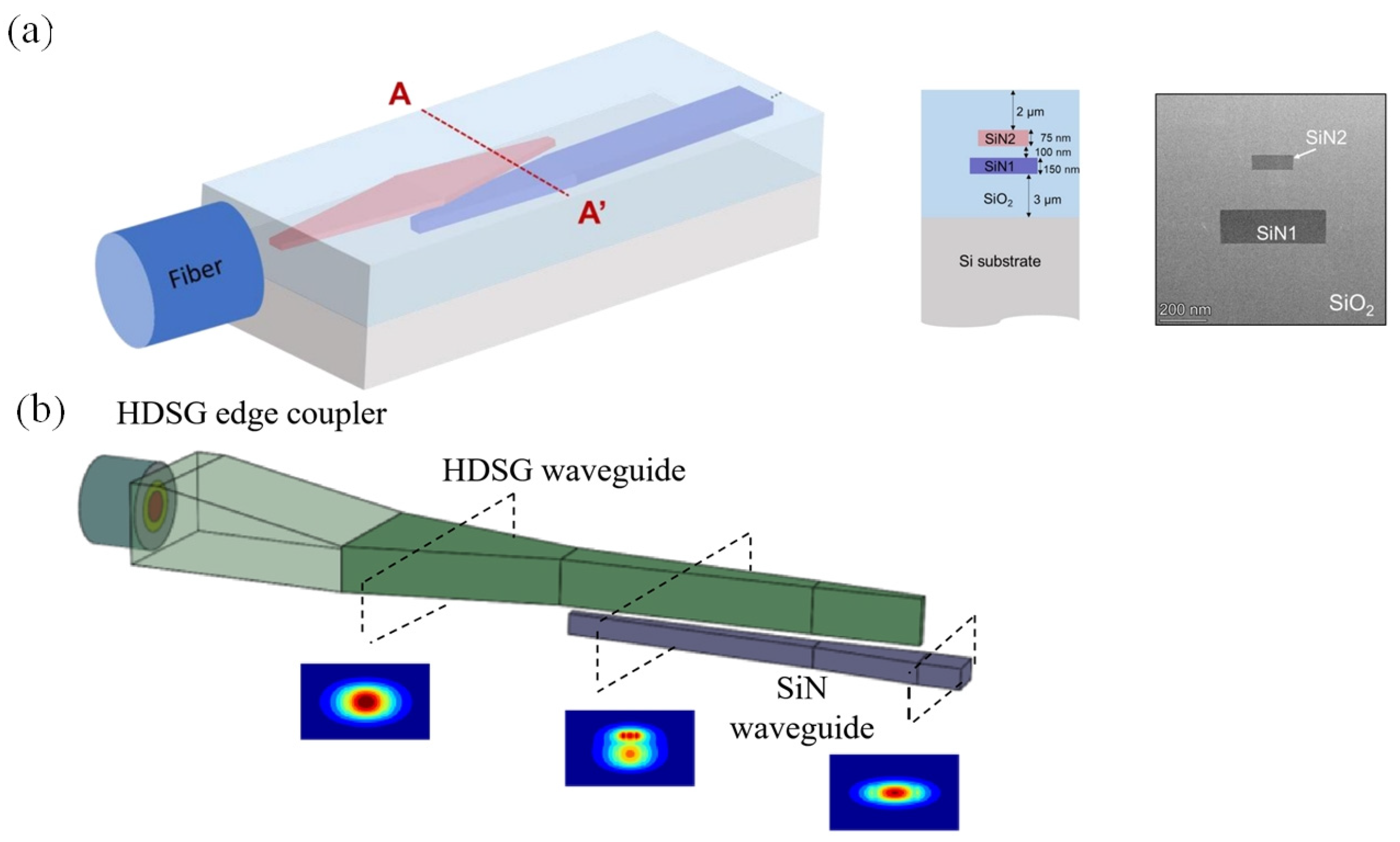
In 2021, Lin et al. designed a SiN EC as shown in Figure 5a. The lower layer is a 150-nanometer-thick SiN1, which serves as the main waveguide routing layer, and the upper layer is a 75-nanometer-thick SiN2 used to expand the mode for efficient fiber coupling. In terms of its shape, there is an inverse taper structure at the starting point of the SiN2 layer, and then the light is transferred to the SiN1 waveguide through an adiabatic interlayer transition. Compared with single-layer designs with the same waveguide confinement and minimum feature size, the coupling loss is reduced by approximately 3–5 dB, and the SiN2-SiN1 interlayer transition loss is less than 0.5 dB across the entire visible spectrum [38]. In 2023, researchers such as Zhu proposed a low-loss fiber-to-chip EC for silicon nitride integrated circuits, as shown in Figure 5b This coupler is based on the silicon nitride integrated optical waveguide platform, uses high-index doped silica glass (HDSG) as the intermediate medium, and consists of an adiabatic coupler and a vertical coupler. The vertical coupler is designed as a multi-stage tapered structure to achieve smooth conversion of optical modes [39].
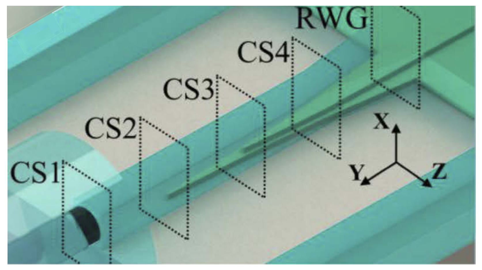
Similarly, the lithium niobate (LN) material is regarded as an ideal material platform for achieving high-performance integrated optoelectronic chips due to its excellent electro-optic, acousto-optic, and nonlinear optical properties. In recent years, with the successful preparation of LNOI thin films at the wafer level and the breakthroughs in micro–nano processing technology, the LNOI platform has demonstrated significant advantages in the integration of large-scale high-speed optoelectronic devices. In 2023, researchers such as Yu proposed and experimentally demonstrated a silicon-nitride-assisted tri-layer EC based on the LNOI platform. The EC consists of a bilayer LN tapered structure and an interlayer coupling structure composed of an 80-nanometer-thick SiN waveguide and an LN strip waveguide [40]. In 2021, researchers such as Hu proposed a highly efficient and polarization-independent EC based on LNOI. This coupler combines a silicon oxynitride cladding waveguide (CLDWG) and adopts a bilayer inverted-taper structure, as shown in Figure 6. When it is coupled with an ultra-high numerical aperture fiber (UHNAF) with a mode field diameter of approximately 3.2 μm, the fiber–chip coupling losses for TE/TM light are 0.54 dB/0.59 dB, respectively, at a wavelength of 1550 nm. This coupler has a large alignment tolerance and good stability [41].
The aforementioned content only introduces the currently implemented ECs in terms of fabrication platforms, optical transmission paths, device structures, and application scenarios. For couplers, their bandwidth, coupling loss, and alignment tolerance are key indicators for evaluating their performance [28,42]. The following table compares the key performance parameters of the above-mentioned ECs.
In summary, the structure optimization of SSCs proceeds in two directions. The first is that the inverse-taper structure changes from a single linear variation to quadratic and exponential variations. The second is that from a single inverse-taper structure to two or even multiple inverse-taper structures, the coupling efficiency has been improved from greater than 1 dB to a minimum of less than 0.1 dB. In the future, it is expected to comprehensively consider these two directions and design multiple inverse tapers with nonlinear variations to comprehensively enhance the coupling efficiency. However, SSCs are usually long in size, making them difficult to apply in applications with requirements on integration size. Edge couplers based on SWG and edge couplers with multi-layer structures provide alternative solutions to this problem.
In terms of performance parameters, ECs based on SWG have made progress in low-loss transmission. As shown in Table 1, the fiber-to-chip EC assisted by SWG features a coupling loss as low as 0.23 dB. In terms of alignment tolerance, ECs with different structures exhibit significant differences. Among them, multi-layer structure designs show better fault tolerance, with an alignment tolerance of up to ±3.1 μm at 0.5 dB loss, while some SWG structures have an alignment tolerance of only 20 nm, imposing strict requirements on mechanical alignment accuracy. In terms of bandwidth coverage, diversified characteristics are presented, including both broadband designs covering the visible wavelength range (445–640 nm) and narrowband optimized schemes adapted to the communication wavelength range (1525–1630 nm), which can meet the wavelength requirements of multiple fields such as nonlinear photonics, communications, and sensing.
However, the performance bottlenecks of current ECs remain prominent. Firstly, there are significant difficulties in the coordinated optimization of performance parameters, making it challenging to simultaneously achieve low loss, high bandwidth, and high alignment tolerance. If a coupler requires low loss, its structure is inevitably complex and difficult to fabricate; if a coupler demands a wide range of applications with long bandwidth coverage, its transmission efficiency is inevitably low. For instance, the fiber-to-chip EC assisted by SWG has a loss as low as 0.23 dB but a bandwidth of only 240 nm while the two-mode multiplexer, despite a simulated bandwidth covering 1260–2000 nm, suffers from a measured loss of up to 2.6 dB and an extremely small alignment tolerance. Secondly, packaging reliability has not been fully verified. Although packaging technologies such as fusion splicing have been applied to platforms like silicon and silicon nitride, the long-term stability and environmental adaptability in large-scale applications still lack systematic verification. Future research needs to further explore paths for coordinated parameter optimization and conduct predictive studies on coupler lifetime to enhance their reliability and durability in practical applications.

3.1.4. Grating Couplers

In the fields of optical communications and integrated optics, the development of high-integration-density optical chips imposes stringent requirements on highly efficient coupling between optical fibers and on-chip waveguides. As a key vertical coupling technology, the grating coupler has become the core solution to address this issue with its unique advantages. This device converts the out-of-plane propagation modes of free-space light into the in-plane transmission modes of waveguides by etching periodic structures on the chip surface, thereby enabling direct coupling between optical fibers or lasers and optical chips. According to the periodic characteristics of the grating structure, grating couplers can be categorized into two types: uniform grating couplers and non-uniform grating couplers, as shown in Figure 7. The design differences between the two types of devices (uniform vs. non-uniform GCs) provide diversified solutions for optical coupling requirements in different scenarios.
The unit period, duty cycle, and etching depth of uniform grating couplers all remain constant; the direction of their slits is perpendicular to the chip interface, and the diffracted mode field exhibits an exponential decay characteristic.
In 2018, Hon et al. proposed an efficient broadband segmented-waveguide grating coupler based on a segmented grating structure. Composed of three uniform gratings, this coupler enables near-vertical optical coupling between waveguides and optical fibers. At a wavelength of 1550 nm, it achieves a coupling efficiency of 51.7%, representing a 25.64% improvement over standard uniform waveguide grating couplers, with a 3 dB bandwidth of 71.4 nm [45]. In 2019, Yu et al. designed a novel dual-layer grating coupler for efficient vertical coupling between the SMF and silicon nanowires. Comprising two 1D gratings, the top grating has a long period and deep etching depth, using low-refractive-index-difference materials to convert vertically incident fiber waves into tilted diffracted waves; the bottom grating features a short period and shallow etching depth to diffract the tilted waves again. The two gratings are separated by a SiO2 gap layer. This coupler exhibits polarization diversity and operates in dual-wavelength bands of 1.3 μm and 1.55 μm [46]. In 2022, researchers from the Korea Advanced Institute of Science and Technology (KAIST) presented a two-layer grating coupler for SOI platforms, utilizing horizontally placed angle-polished single-mode fibers. The structure consists of two fully etched silicon grating layers stacked vertically, with parameters such as etching depth, grating period, vertical shift between layers, fill factor, and tilting angle optimized to enhance performance. It enables efficient optical signal coupling for both chip-to-fiber and fiber-to-chip transmissions [47]. In 2024, Zhou et al. introduced a perfectly vertical broadband grating coupler (PVBGC) based on a resonance-enhanced center-symmetric structure. With a simple structure requiring only a single etching step, a minimum feature size larger than 150 nm, and excellent fabrication tolerance, this design represents a significant advancement [43].
Non-uniform grating couplers adopt a quasi-periodic structure. By dynamically adjusting the period, duty cycle, or etching depth along the light propagation direction, they break the strict periodicity of traditional gratings. This allows the optical field shape diffracted from the SOI grating structure to follow a Gaussian distribution, enabling the optical field diffracted by the waveguide grating to match that of the SMF, thereby optimizing the optical field matching efficiency.
In 2015, Yu et al. proposed a high-efficiency binary blazed grating coupler for chip-level optical interconnections, including both perfectly vertical and near-vertical configurations; the structure consists of rectangular pillars with uniform height but varying widths, formed by binary quantization approximation of traditional triangular-tooth gratings. This coupler addresses the coupling challenges arising from refractive index and mode-size mismatches between silicon chips and the external SMF, enabling efficient transfer of light from fibers into chip waveguides [48]. In 2024, Chen et al. developed a vertical backside-coupled silicon GC structure. At a wavelength of 1550 nm, it achieves a 1 dB bandwidth of 20 nm and a coupling loss as low as −3.97 dB, demonstrating excellent optical transmission performance. Additionally, it exhibits robust alignment tolerance: within ±3 μm lateral offset and ±5° angular misalignment, it maintains high coupling efficiency. This significantly reduces the difficulty of optical alignment in fiber-to-PIC connections, ensuring stable optical signal transmission and enhancing the reliability and practicality of optical interconnections [44].
After the diffraction of incident light through the grating, the optical power is divided into three main parts: the upward-reflected power, the power leaking downward through the substrate, and the power coupled into the waveguide. Therefore, in addition to the aforementioned method of matching the fiber and waveguide modes to improve coupling efficiency, other approaches can be adopted. These include placing a metal mirror or a distributed Bragg reflector at the interface between the SiO2 layer (below the waveguide plane) and the substrate, or shaping the grating teeth with a staircase profile via multiple etching steps to mimic the behavior of blazed gratings. In 2022, Lomonte presented preliminary results on fabricating self-imaging apodized grating couplers integrated with a metal back-reflector. Their experimental findings show that the coupler achieves a coupling efficiency of approximately −3 dB at the operating wavelength of around 1550 nanometers, nearly doubling the efficiency of conventional grating couplers on Si substrates (5 dB). With proper optimization of the fabrication process, they anticipate demonstrating couplers with insertion losses below 0.5 dB [49].
As outlined in Table 2, grating couplers are advancing toward the direction of low loss and large bandwidth. In recent years, researchers have improved performance through structural innovations, such as multi-layer grating structures and non-uniformly etched gratings. However, such devices still face the challenge of balancing bandwidth and coupling efficiency, and their polarization sensitivity exhibits significant differences. For example, the dual-layer grating coupler has a coupling loss of 4.83 dB for the TM mode and 3.87 dB for the TE mode at a wavelength of 1.56 μm [36]. Similarly, the packaging reliability of grating couplers has not yet been fully validated. Future research needs to further investigate their long-term stability and environmental adaptability to enhance their reliability and durability in practical applications.
Each type of coupler mentioned above has its own advantages and disadvantages, and the appropriate coupler needs to be selected according to different application scenarios. Edge couplers based on SSC and subwavelength gratings (SWGs) have high coupling efficiency, although their large length conflicts with the current high-density integration. They are suitable for application scenarios where the requirement for integration density is not high and there is sufficient dimensional space. Compared with single-layer edge couplers of the same structure, multi-layer structures can reduce coupling loss by 3–5 dB, making them suitable for multi-platform application scenarios and those with strict requirements on the coupling loss. The optical coupling into and out of the waveguide of edge couplers occurs on the side of the chip, and light always propagates in the same plane. Compared with grating couplers, they have the characteristics of wide bandwidth, low loss, and polarization insensitivity, making them suitable for packaging and integration between optical fibers and PICs; however, they also have disadvantages. For example, the alignment tolerance requirements are strict. The misalignment tolerance of edge couplers is equivalent to the manufacturing tolerance of fiber arrays. Therefore, edge coupling is only suitable for single-channel packaging. When multiple optical fibers need to be connected, high-precision alignment work will consume a lot of time and cost. The long device size and large footprint are not conducive to scenarios with higher integration requirements. The device manufacturing process requires undercut and deep-etching processes, and tiny process errors may cause problems in device stability and reliability. In particular, edge couplers can only support the end-face coupling of PICs, which have strict requirements on the positions of PICs and optical fibers, greatly limiting their application scenarios. Grating coupling can couple light from optical fibers placed perpendicular to the PIC into the planar PIC by fabricating appropriate diffraction gratings through a simple two-step etching process. This means that the PIC has flexible position selection on the board without a fixed coupling position, and the grating coupler has a small size, enabling wafer-level testing. Therefore, grating couplers can cope with application scenarios with higher integration requirements. However, grating couplers also have disadvantages. The light that meets the phase condition is successfully coupled into the waveguide, although the components of light that do not meet the phase matching condition are eliminated during propagation in the grating, which leads to low coupling efficiency and narrow bandwidth of grating couplers, making them unsuitable for application scenarios that require high-light-propagation efficiency and wide bandwidth coverage. Similarly, grating couplers have high polarization sensitivity, resulting in inconsistent coupling efficiency for light of different polarization states. If the polarization state of light changes in practical applications, the optical power coupled into the waveguide will be unstable, affecting the normal operation of the system.
In summary, in the practical application of packaging between optical fibers and photonic chips, grating couplers have become the current mainstream technical solution due to their significant advantages. From the perspective of large-scale commercialization, this technology not only has the characteristics of low-cost and flexible testing—which can effectively reduce the testing cost and complexity in the mass production process—but also has the characteristics of compact size and no position restrictions on the layout of PICs, which can significantly improve the integration density of chips and meet the design requirements of high-density photonic integrated systems. In contrast, the core advantage of edge couplers lies in their low-coupling-loss characteristics. Therefore, this technology is more suitable for single-channel packaging scenarios with strict requirements on coupling efficiency, especially in applications with low cost sensitivity and low integration requirements, where it can give full play to its advantages of low loss. The selection of application scenarios for the two needs to be weighed based on actual requirements: grating couplers are more suitable for large-scale, high-integration commercialization needs, while edge couplers show irreplaceability in single-channel scenarios where low loss is a priority.

3.2. Photonic Wire Bonding

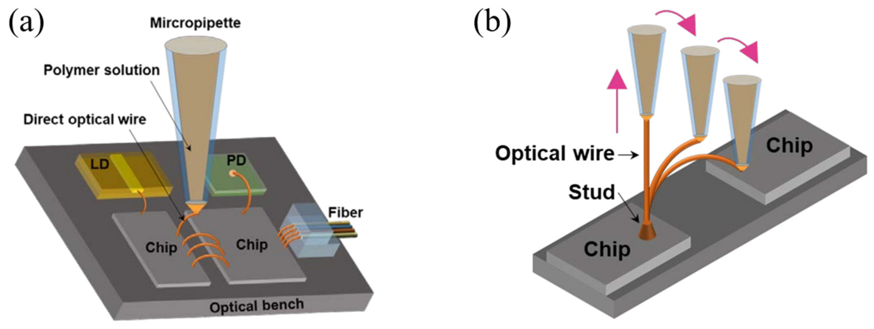
Optical input/output (I/O) coupling technology serves as a critical interface to enable efficient connectivity between chips and external fiber networks. The current mainstream coupling schemes are the in-plane edge coupling and out-of-plane grating coupling technical approaches introduced above. With the continuous increase in on-chip integration density, optical interconnection technology faces dual challenges of manufacturing complexity and cost control. Current manufacturing processes relying on active alignment technology suffer from low production efficiency and high costs, making them difficult to meet future high-density integration requirements [50]. The rapidly developing PWB technology in recent years is expected to become a key direction for breaking through existing bottlenecks, providing an attractive potential alternative. The PWB technology can be used not only for low-loss connections between optical fibers and Si chips but also for interconnecting waveguides between different functional chips on Si substrates [51,52], as shown in Figure 8. Using computer vision and automation, PWBs can be fabricated in polymer photoresist through two-photon absorption between two coupling sites, allowing misalignments of up to 30 μm. Simple alignment markers are used to locate the coupling sites, which do not require strict pitch or large footprints, thereby providing passive alignment, low loss, and a scalable port count [53].
In 2015, German researchers led by Lindenmann demonstrated that PWB technology is an effective method to overcome the limitations of traditional coupling techniques. They fabricated free-standing polymer waveguides via in situ 3D direct laser writing, achieving low-loss connections between multi-core optical fibers and silicon photonic chips. This technology employs a two-photon polymerization process to create waveguides with a diameter of 2 μm, optimizes mode matching through tapered structures, and uses trajectory optimization algorithms to avoid obstacles, effectively compensating for fiber core position tolerances. Experimental results showed that the minimum insertion loss between four-core fibers and silicon chips reached 1.7 dB, with simulated losses as low as 1.3 dB. The technology requires no active alignment, making it suitable for automated production. This approach provides an innovative solution for efficient interconnection between multi-core fibers and photonic chips. Through process optimization, the loss is expected to be reduced below 1 dB, laying the foundation for the development of high-density integration and spatial multiplexing technologies in optical communication systems [54]. In the same year, researchers from Gu’s group utilized a PWB based on SU-8 two-photon polymerization to achieve optical transmission between III–V chips on silicon. They first determined the fabrication conditions for PWBs and numerically simulated their coupling structures with III–V optical components. Experiments were then conducted to fabricate 2.5-micrometer-wide PWBs with a 1:3 aspect ratio between two optical chips with a 140-micrometer gap, realizing optical transmission. The coupling loss for each side (laser or detector chip) was approximately 5 dB, with a total connection loss of about 10 dB. The study confirmed the feasibility of PWB technology, providing a direction for future developments in photonic bonding. PWBs hold the potential for 3D freeform integration of different optical components, enabling high-performance on-chip optical interconnections without compromising device performance [55].
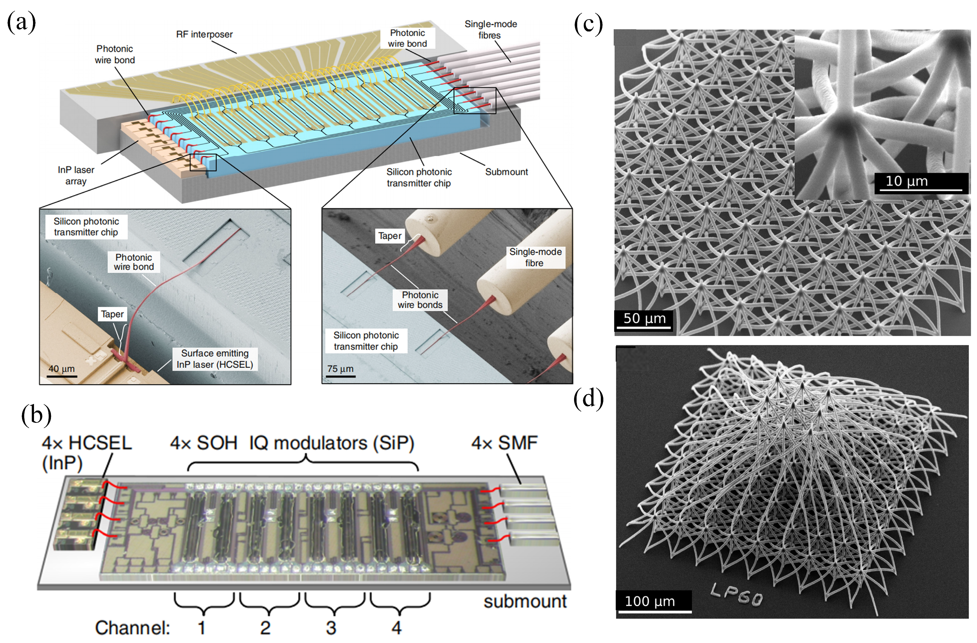
In 2020, Zvagelsky et al. studied the 3D PWB technology, which realizes three-dimensional optical interconnections between chips through direct laser writing or two-photon lithography. This technology has become a key technology to break through the limitations of traditional planar integration. For the first time, silicon nitride nanophotonic circuits were combined with 3D polymer waveguides. Through the design of a hybrid waveguide with a Gaussian shape and a circular top, the transmission loss was optimized to 5 dB at a wavelength of 1.55 µm. The feasibility of 3D bent waveguides was verified, and the concept of multi-level crossing was proposed to solve the crosstalk problem of planar waveguides, laying a material and structural foundation for the 3D integration of photonic chips [56]. In 2020, Blaicher’s team achieved high-density integration of multi-chip modules (MCMs) through in situ nanolithography technology, as shown in Figure 9a,b. They demonstrated 100 densely arranged photonic wire bonds (PWBs) with a pitch of 25 µm and an average loss of 0.73 dB. They also successfully constructed optical communication engines with 8-channel 448 Gbit/s intensity modulation and 4-channel 784 Gbit/s coherent modulation, setting a record for the highest data rate of silicon photonic transmitters. This technology has verified its reliability through environmental stability tests (temperature cycling and damp heat), solved the problem of high-precision alignment in traditional optical chip assembly, promoted the automated production of multi-chip modules, and accelerated the commercialization process of optoelectronic devices [57].
The research of the two teams has promoted the development of 3D photonic wire-bonding technology from two dimensions: basic technological innovation and practical system application. The former provides theoretical and process support for high-density photonic interconnection, while the latter pushes the technology towards industrial application. Together, they have built an important milestone in the fields of optical communication and photonic integration.
In the same year, the research team led by Moughames from France proposed an integration scheme for neural networks based on three-dimensional PWBs. The study applied fractal topology to the design of 3D optical couplers, as shown in Figure 9c,d, for the first time. Waveguide interconnects with a diameter of 1.2 μm were realized through two-photon polymerization technology. In total, 225 input and 529 output channels were integrated within an area of 0.46 × 0.46 mm2, breaking through the bottleneck in 2D technology where the area grows quadratically with the number of channels. Discrete spatial filters matching deep convolutional neural networks (CNNs) were constructed, and the parallel calculation of Haar convolution kernels was successfully achieved, verifying the feasibility of 3D photonic circuits in CNN feature extraction. This achievement provides a new paradigm for the development of photonic wire-bonding technology: the linearly scaled 3D architecture can compress the interconnections between 2200 neuron layers into a volume of 1 mm3, laying the foundation for the high-density integration of neuromorphic chips. Meanwhile, it offers a mass-producible technical path for inter-chip optical interconnection and optical computing expansion [58].
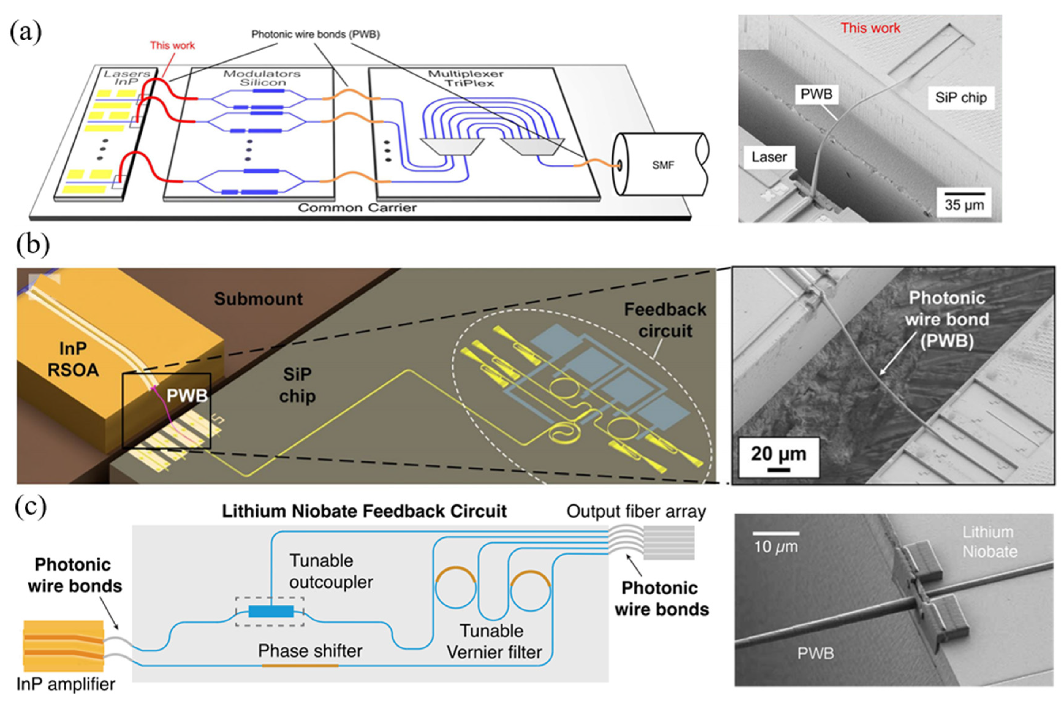
High-performance lasers can also be constructed using photonic wire-bonding technology. In 2018, Billah et al. achieved efficient coupling between indium phosphide (InP) horizontal-cavity surface-emitting lasers (HCSELs) and silicon photonic chips by in situ fabrication of three-dimensional freeform polymer waveguides via two-photon lithography, as shown in Figure 10a. This technology employs a 3D freeform waveguide design that dynamically compensates for chip position tolerances, enabling side-by-side mounting of the laser and the silicon chip to optimize heat dissipation, and combines two-photon lithography to achieve automated high-density integration. In experiments, they achieved an insertion loss as low as 0.4 dB between the InP laser and the silicon nanowire, and verified the loss mechanism through numerical simulations [59]. In 2021, researchers led by Xu et al. from Germany proposed a hybrid external-cavity laser (ECL) integration scheme based on PWBs. Figure 10b illustrates the core device structure: a 3D-printed PWB connects an InP-based reflective semiconductor optical amplifier (RSOA) to a thermally tunable feedback circuit on a silicon photonic chip, enabling low-loss inter-chip coupling. The PWB is fabricated in situ via a fully automated process, with its geometry adapted to the mode-field sizes and positions of both chip facets—compensating for assembly misalignments without requiring high-precision alignment techniques. The study demonstrated a high-performance laser with a 50 nm tuning range (1515–1565 nm), side-mode suppression ratio (SMSR) > 40 dB, and intrinsic linewidth of 105 kHz. The innovation in Figure 10b lies in the first application of 3D-printed photonic wire bonding for intra-cavity coupling, overcoming the traditional hybrid integration’s reliance on sub-micrometer alignment tolerances [60]. In 2025, researchers such as Franken utilized photonic wire bond (PWB) technology to integrate InP amplifiers with a thin-film lithium niobate (TFLN) feedback circuit, fabricating a high-performance extended-cavity diode laser as shown in Figure 10c. This laser features a side-mode suppression ratio exceeding 60 dB and a wavelength tuning range of up to 43 nm. At high currents, it can achieve a maximum on-chip power of 76.2 mW with a side-mode suppression ratio of 51 dB. Its intrinsic linewidth is only 550 Hz, and it can operate stably for 58 h without mode hopping, with a frequency drift of 4.4 MHz/h. The research verifies the feasibility of PWBs for the integration of high-performance on-chip lasers, opening up the path to system-level scaling and watt-level output powers. In the future, it is expected to enhance the laser performance by optimizing PWB transmission and reducing losses, and promote its integration with more functions of the TFLN platform, facilitating the development of photon-bonding technology in fields such as optical communication and microwave photonics [61].
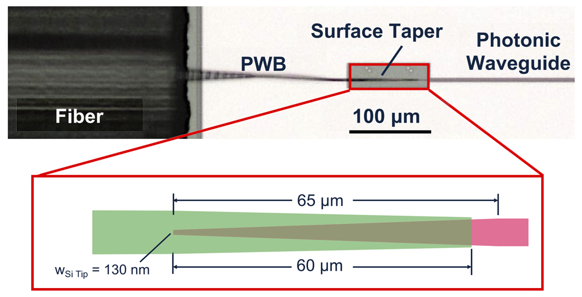
Research on the adaptability of photonic bonding technology to extreme environments is also of great significance. In 2023, Lin et al. studied the application of photonic wire bonds (PWBs) in cryogenic optical packaging, as shown in Figure 11. The research achieved low-loss (2 dB per channel) connections between a single-mode fiber array and tapered silicon waveguides at temperatures as low as 5 K using PWBs. This research features large alignment tolerances, with lateral and axial alignment tolerances greater than 30 μm and 100 μm, respectively. It can achieve adiabatic mode conversion, effectively coupling large-sized fiber modes with small-sized waveguide modes. It also has a large operating bandwidth as the polymer used has low absorption in the O and C bands. Moreover, it has stable mechanical properties and is more resistant to vibrations from nearby pumps and compressors. Meanwhile, the research demonstrated its excellent performance under various experimental conditions. For example, its performance remained stable during multiple cooling cycles, it could withstand vacuum baking, and it could successfully enable silicon micro-ring resonators to exhibit nonlinear behavior at low temperatures. In addition, compared with other cryogenic fixed coupling methods, a PWB performs better in terms of insertion loss, coupling bandwidth, spectral shift, polarization-dependent loss, and misalignment tolerance. It can be used for large-scale integrated packaging, providing a promising solution for the interconnection of photonic devices in extreme environments [62].
The recently emerged PWB technology is a key integrated packaging technology for achieving high-density interconnection of photonic chips. The manufacturing steps of this technology are simple: the PWB is directly formed by controlling the glass micropipette filled with polymer solution, similar to the integrated operation of wire bonding. The writing time for a single PWB is expected to be shortened to a few seconds, meeting the requirements of high-volume production. It offers high optical-path flexibility with no restrictions on the position of PICs, enabling both in-plane and out-of-plane coupling. Traditional couplers require active alignment technology during packaging, which increases costs. In contrast, for PWBs, before fabrication, the chip and optical fiber only need to be mounted on a common substrate. The actual positions of the fiber cores and chip waveguides are detected through 3D machine vision, and the waveguide trajectory is calculated in real-time to ensure accurate docking of both ends of the waveguide to the target positions, without the need for pre-alignment in this process. Through a closed-loop process of position detection, trajectory customization, and structural compensation, PWBs eliminate the necessity of active alignment at the process level, essentially replacing dynamic adjustment with a passive alignment strategy based on structural design. The most significant advantage of PWBs is that they can break through the limitations of 2D integration, distribute input and output ports on independent planes, and realize wiring using the third dimension. Complex fractal and hand-shaped structures can be fabricated through 3D direct-write technology, which can significantly improve the flexibility of chip distribution on the board, reduce design difficulty, and further increase integration density. The development of this technology will directly affect the system power budget and the upper limit of integration density of optoelectronic devices. Combining this technology with traditional coupling technologies is definitely the future development direction of PICs, which is of great significance for promoting the large-scale application of silicon photonic technology in fields such as optical communications and data centers.

4. Co-Packaged Optics

With the rapid development of data-intensive applications (such as high-performance computing, large-scale data centers, and distributed computing), traditional copper interconnects—constrained by bandwidth bottlenecks and power consumption limitations—have been increasingly unable to meet the requirements for high-speed, low-latency communication in next-generation systems. Silicon photonic technology, leveraging its high bandwidth density, low signal loss, and compatibility with CMOS technology, is gradually replacing copper interconnects [63] and has become the core solution for communications ranging from telecommunication networks, inter- and intra-data center communications, to intra-package interconnects. Within this technical framework, optical communication systems typically consist of three core components: a source ASIC and its associated optical engine (OE); a destination ASIC and its associated OE; and optical channels linking the source OE and destination OE, where the optical channels can be optical fibers and/or optical waveguides. Among them, optical fibers are suitable for long-distance communications over meter-scale distances to leverage the advantage of low propagation loss, while optical waveguides dominate short-distance interconnects due to their higher bandwidth density. When an OE and its corresponding ASIC are packaged on the same substrate through heterogeneous integration technology, CPO [64] technology emerges, serving as a key pathway to break through package-level bandwidth bottlenecks.
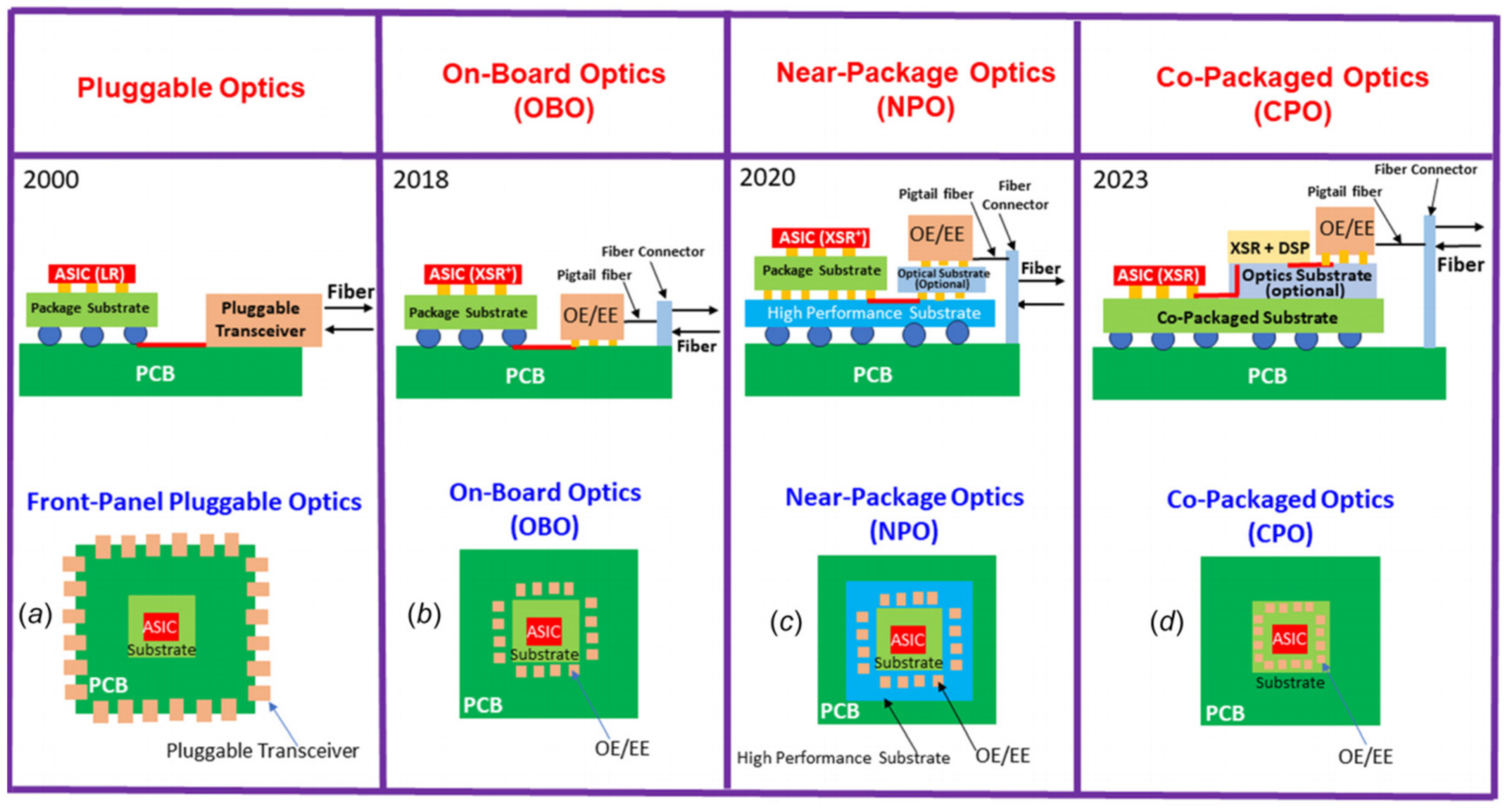
Over the past two decades, optical module technology has evolved from discrete pluggable forms to deeply integrated solutions, as shown in Figure 12. Early pluggable modules (such as Small-Form-Factor Pluggable, SFP, and Quad Small-Form-Factor Pluggable, QSFP) enabled flexible deployment through standardized interfaces; however, their separate packaging of PIC/electrical integrated circuits (EICs) and ASIC, relying on printed circuit boards (PCBs) for electrical connections, resulted in long signal transmission paths and high power consumption (especially at rates above 25 Gbps).
The On-Board Optics (OBO) technology, emerging in 2018, first integrated the optical engine with the ASIC on the same PCB, improving electrical performance by reducing the distance between PIC/EIC and ASIC. The Near-Package Optics (NPO) technology, developed in 2020, further utilized high-performance substrates to connect the ASIC and optical devices, reducing the signal transmission distance to 150 mm and controlling the channel loss within 13 dB [65], expanding the application space for Extra Short Reach (XSR) interface technology.
However, as data centers upgrade to 51.2 Tbit/s and higher rates, the requirements for bandwidth, power consumption, and integration density in high-density intra-packaging interconnects have reached new heights. The signal loss, electromagnetic interference, and packaging volume limitations of PCBs or interposers in traditional technologies can no longer meet the next-generation systems’ needs for “chip-level optical interconnects” [66,67].
The CPO technology integrates the optical engine, electrical engine, and ASIC chip directly side by side on the same co-packaged substrate (such as a through-silicon-via interposer or a glass substrate), achieving the hermetic packaging of three core components. The distance between the ASIC and the PIC/EIC is shortened to within 50 mm; the channel loss is reduced to less than 10 dB. The significant shortening of the electrical interface path brings a loss savings of more than 3 dB and lower drive power consumption [65]. Meanwhile, it eliminates the parasitic effects of PCB-level interconnections. This heterogeneous integration mode of “chip-level collaboration” not only breaks through the bandwidth wall of traditional packaging but also provides a solution with both performance and energy efficiency for high-density optical interconnections through the integration of silicon photonic technology and advanced packaging processes. From the perspective of technological evolution, CPO represents an inevitable trend of optical modules, which has evolved from “device-level integration” (pluggable modules) to “package-level integration” (OBO/NPO) and then to “chip-level collaboration”. Its core advantage lies in the systematic optimization of the packaging architecture to achieve the coordinated improvement in the photoelectric hybrid system in terms of bandwidth, power consumption, and density.
For example, IBM has applied CPO in low-diameter, large-scale, high-performance computing and data center networks. Research has found that CPO can significantly increase the switch escape bandwidth, enabling the implementation of high-radix switches with over 150 ports and a rate of 400 Gb/s. From the perspective of network architecture, it can eliminate the third-layer switching and build large-scale topologies with over 11,000 end points. The bisection bandwidth is increased by 4 times, and the number of switch ASICs is reduced by over 80%. In terms of network operation, both energy consumption and packet delay are reduced. Simulation results show that in various traffic scenarios, CPO can improve the average packet delay by 30%–74%. In conclusion, CPO is a promising solution for future network bandwidth expansion [68].

4.1. Two-Dimensional CPO

CPO is divided into three packaging forms—2D, 2.5D, and 3D—according to the chip stacking form, each with different technical characteristics, advantages, and disadvantages. In 2D packaging, the PIC and the EIC are placed side by side on a substrate or PCB and interconnected through wires or substrate wiring. Its advantages include simple processes, easy packaging, and high flexibility as the PIC and EIC can be independently fabricated using different materials and processes; however, its disadvantages are that the planar layout of the chips leads to relatively long interconnection paths, large high-frequency signal transmission losses, and relatively low packaging density. In 2022, Chou et al. proposed and verified a highly integrated optical engine design based on fan-out wafer-level packaging (FOWLP), as shown in Figure 13. In the study, the EIC and the PIC were flip-chip bonded, and the fan-out substrate was used to realize signal redistribution; this was connected to the switch ASIC board through an elastomer socket, effectively optimizing signal integrity, reducing material and packaging costs, and enhancing integration density and the reworkability of the optical engine. The researchers compared four packaging schemes and demonstrated the significant advantages of the fan-out EIC scheme in 2D electrical connections, channel density, and process compatibility. In the experimental part, based on a 25 Gbps/ch chipset, the DC, S-parameter, and functional tests of the optical engine were completed. The results show that the bandwidth attenuation introduced by the packaging is only about 2 GHz, and error-free operation was achieved, verifying the applicability of this scheme for next-generation 800 Gbps+ chipsets and providing a feasible engineering path for the large-scale application of CPO technology in high-speed data centers [69].

4.2. The 2.5D CPO

The 2.5D packaging enables chip interconnection through an interposer. The PIC and EIC are flip-chip bonded onto the interposer, connected via the metal wiring of the interposer, and then linked to the underlying substrate or PCB. It features higher interconnection density and lower power consumption, with the interposer providing both mechanical support and electrical interconnection functions.
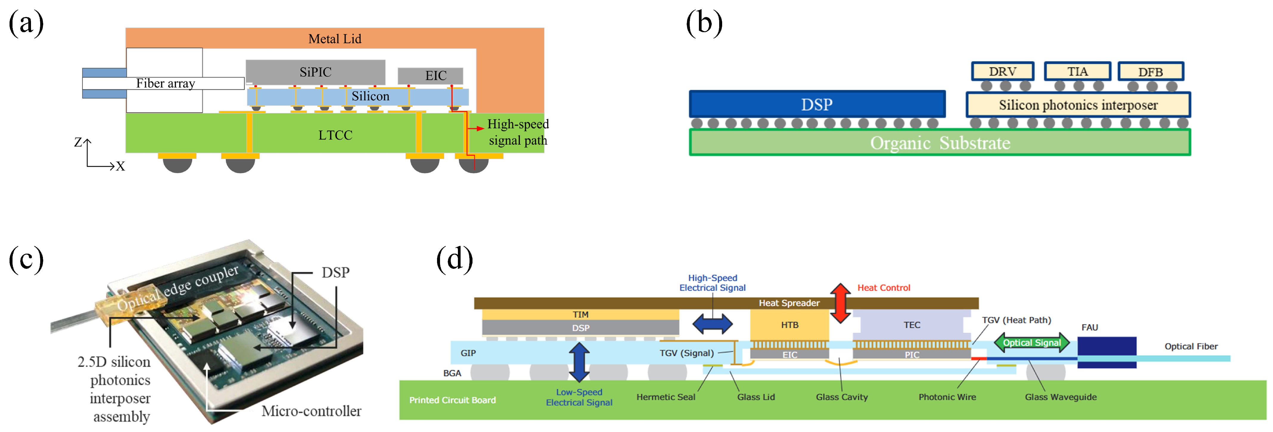
In 2022, the Institute of Microelectronics, Chinese Academy of Sciences, developed a multi-channel high-bandwidth transmitter integrating a silicon photonic Mach–Zehnder Modulator (MZM) in a 2.5D optoelectronic co-packaged configuration. The fabrication process involved mounting the silicon interposer onto the LTCC using flip-chip technology. Subsequently, passive components such as filter capacitors were assembled on the silicon interposer. Then, the EIC and SiPIC were mounted using thermal reflow technology. After that, low-temperature SnPb solder was used instead of traditional solder to achieve the BGA mounting and interconnection under the LTCC. Finally, the fiber array was edge-coupled to the SiPIC using a UV-curing adhesive; the metal lid was also mounted on the surface of the LTCC with a UV-curing adhesive to provide mechanical protection and auxiliary heat dissipation. This transmitter exhibits an insertion loss of less than −1.55 dB at 40 GHz, ensuring a clear eye diagram output for 64 Gbps PAM4 signals, and has the potential to achieve 100 Gbps PAM4 signal transmission [70].
In 2023, Marvell implemented the CPO technology using 2.5D heterogeneous integration based on silicon photonics. First, 2D integration was carried out on a silicon photonic chip. The driver amplifier (DRV) for the transmitter, the transimpedance amplifier (TIA) for the receiver, and the DFB lasers were integrated onto a common silicon photonic substrate through the flip-chip (FC) method. This substrate also contains optical components such as the MZM, power and wavelength splitters, combiners, and high-speed photodetectors (HSPDs). Then, using through-silicon vias (TSVs) and backside solder bumps, the silicon photonic interposer with these components was assembled on a high-speed organic substrate and underwent 2.5D assembly with high-speed digital signal processors (DSPs) and controller application-specific integrated circuits (ASICs). A planar lightwave circuit (PLC) fiber array assembly was used as the optical signal EC between the chip and the fiber. This prefabricated multi-fiber assembly was actively aligned with the silicon photonic chip and then fixed to the substrate with epoxy resin to achieve the connection between the fiber and the chip, with an optical coupling of less than 1 dB, thus realizing the high integration of CPO. If the 2D components are stacked on the DSP, it becomes a 3D component [71].
In addition to the traditional TSV technology, TGV (through-glass via) methods can also be used for high-density interconnection [72]. For example, in 2024, Sumitomo Corporation proposed a CPO packaging technology based on a photonic-wire-bonded glass interposer (GIP). Its core structure is shown in Figure 14d: The GIP is mounted on a printed circuit board (PCB) through a ball grid array (BGA). A digital signal processor (DSP) is mounted on the front side, and a PIC and an EIC are installed on the back side via the BGA side. Hermetic packaging is achieved through a glass lid. Inside the package, the PIC and the glass waveguide achieve high-efficiency optical coupling without active alignment through photonic wire bonding (with a coupling efficiency of −1.9 to −2.3 dB in the C-band). Optical signals are led out from the Fiber Array Unit (FAU) at the edge of the GIP through the glass waveguide. The EIC and the DSP transmit ultra-high-frequency electrical signals through hermetic through-glass vias (TGVs). Electromagnetic analysis shows that its transmission characteristics are resonance-free and have low loss above 120 GHz. In terms of thermal management, a Thermoelectric Cooler (TEC) controls the temperature of the PIC through a hermetic thermal path composed of high-density TGVs in the GIP. The thermal insulation property of the glass effectively suppresses the thermal crosstalk from the EIC to the PIC. This packaging structure realizes the efficient extraction of optical signals, electrical signals, and heat, providing a platform that is compatible with hermetic sealing, thermal control, and ultra-high-frequency signal transmission for the high-density hybrid integration of compound semiconductor optical sub-assemblies (OSAs) and ASICs [73].

4.3. Three-Dimensional CPO

The integration of optical modules has evolved from monolithic integration to 2D integration, 2.5D integration, and finally to 3D integration [74]. Wire bonding exhibits low-pass characteristics, which impose significant limitations on high-frequency responses [75]. Moreover, the issue of an optical interface facing downward is difficult to resolve using 2.5D integration. Therefore, 3D integration with an active photonic interposer has become the most popular approach. The 3D packaging adopts a vertical stacking method and realizes the three-dimensional interconnection of optoelectronic chips through TSVs or micro-bump technology. Its core advantages include short interconnection distances, excellent high-frequency performance, high integration density, and compact packaging, making it suitable for high-speed and compact scenarios. Compared with traditional 2D/2.5D integration, 3D integration significantly shortens the transmission distance from electrical chips to optical chips, contributing to a further increase in the transmission bandwidth. Meanwhile, the area of the entire module is greatly reduced, and the integration density is enhanced.
In 2022, the Institute of Microelectronics of the Chinese Academy of Sciences (IMECAS) designed and fabricated an active photonic interposer on a SOI wafer. As shown in Figure 15a, in a 3D optical module, the active photonic interposer consists of an on-chip laser (or an external laser), an optical waveguide, an optical modulator, an optical amplifier, and an optical detector. Electrical chips (such as DSP and Clock and Data Recovery, CDR) are integrated onto the interposer through the Redistribution Layer (RDL) and micro-bumps. The entire module is connected to the outside through TSVs, the bottom RDL layer, and solder balls. The vertical interconnection of the EIC on the PIC can be achieved using Solder-Ball-Bumps (SBBs) or Copper-Pillar-Bumps (CPBs). RDLs are regarded as inter-chip interconnections, and TSVs are regarded as external chip interconnections, which greatly shorten the interconnection path between the EIC and the PIC and reduce reflections. The test results show that at a frequency of 67 GHz, the insertion loss of the RDL can reach 0.35 dB, and the 56 GBaud (112 Gbps) eye diagram indicates excellent signal transmission quality. The coupling loss of the EC is 1.69 dB/facet. An active optical interposer integrating an EC and a through-silicon via was designed and fabricated for the first time. This interposer exhibits good high-frequency characteristics and optical performance, providing a research basis for the large-scale application of 3D-based co-packaging for Optoelectronic Integrated Circuit (OE-IC) system integration [76].
In 2023, Wang et al. conducted research on 3D CPO technology for four-channel silicon photonic mode-division multiplexing (MDM) and wavelength-division multiplexing (WDM) transmitter chips, and proposed a high-density integration scheme based on flip-chip bonding, as shown in Figure 15b. The research focused on the heterogeneous integration of silicon photonic transmitter chiplets and driver chips. The silicon MDM-WDM transmitter chiplet was mounted on a printed circuit board (PCB), and the driver chip was vertically stacked on top of the silicon photonic transmitter chiplet through gold bump flip-chip bonding technology to achieve pin-to-pin electrical interconnection. Bond pads and metal lines were fabricated on the silicon photonic transmitter chiplet through a standard metallization process for high-speed signal transmission and bias control of the driver chip and each channel’s micro-ring modulator (MRM). This scheme significantly shortened the electrical interconnection length through 3D stacking and improved the integration density [77].
In recent years, major packaging companies have successively launched their own 3D chip-stacking solutions. In 2024, Cisco introduced a 25.6T system with 3D CPO packaging based on a 110 × 110 mm2 low-loss organic ball grid array (BGA) substrate, integrating a 25.6T ASIC silicon die assembly with eight optical engines adopting 3D fan-out packaging technology. Each optical engine integrates 4 × 800 G EICs and 1 × 3.2 T PICs within a single package, achieving short-distance and low-parasitic electrical interconnections through top and bottom redistribution layers (RDLs) and high-density copper pillars.
The optical engines are connected to the substrate via custom uLGA sockets, enabling pluggable and serviceable functionality. The substrate is equipped with a metal frame to control large package warpage and guide precise alignment. An external pluggable laser source provides low-loss optical power to the optical engines through polarization-maintaining optical fibers (PMF). A 24-channel fiber array is interconnected with the PIC via die-edge optical coupling technology, with an optical loss of less than 1.5 dB per channel.
By optimizing signal integrity, thermal management, and package warpage, the system achieves a 25% power consumption reduction compared to traditional systems under the same ASIC and power components conditions. Both the bit-error rate (BER) and packet loss rate meet IEEE standards, verifying the feasibility of 3D packaging technology in achieving high-density and low-power consumption interconnections in hyperscale data center networks [78]. In the same year, Broadcom also introduced a CPO packaging technology based on CMOS silicon photonic chiplets, constructing a module with an optical engine bandwidth of 6.4 Tb/s. This module was co-packaged with a switch die to form an all-optical 51.2 Tb/s CPO switch solution. The technology co-packages eight optical engines with a switch die featuring 512 channels each operating at 100 Gb/s, doubling the bandwidth of the standard 25.6 Tb/s solution without increasing system power consumption. It created the industry’s first prototype system of this kind, achieving efficient heterogeneous integration of silicon photonic chiplets and switch die, and providing a high-bandwidth, low-power consumption connectivity solution for data centers [79].
In 2024, leveraging its I-CubeE advanced packaging technology for electronic chips, Samsung developed the 3.5D CPO platform (Figure 16). This platform integrates 3D stacked PICs and EICs into an organic RDL interposer, with connections via a silicon bridge, forming a 3.5D packaging solution for efficient optoelectronic engine integration. Since the TSV process has a significant impact on signal integrity [80], the study analyzed the signal integrity of the Die-to-Die (D2D) interface based on the Universal Chiplet Interconnect Express (UCIe) specification. It simulated the simplified I/O models of the transmitter and receiver, the W-element interconnect of the silicon bridge, and the TSVs in the PIC, focusing on insertion loss, crosstalk, and eye diagram performance. Simulation results show that with a 2 mm channel length, the platform can support data rates of 24 Gbps and 32 Gbps without equalization, with insertion loss and crosstalk meeting UCIe specification requirements. Further analysis indicates that reducing the TSV height can improve signal integrity. When the receiver load capacitance is controlled at 0.1 pF, it is expected to support a higher data rate of 40 Gbps. The study verified the advantages of I-CubeE technology in terms of cost efficiency, scalability, and productivity, providing a feasible technical solution for high-performance, low-power CPO packaging [81].
Each of the three packaging forms has its own focus: 2D packaging technology is a traditional and widely used packaging method. After long-term development, it has become very mature in terms of processes, materials, and equipment, with high reliability and stability. The mature processes result in a high yield rate during production, and the costs of required equipment and materials are relatively fixed, leading to obvious cost advantages in large-scale production. However, the interconnection length between the chip and the optical module is relatively long, which causes serious phenomena such as loss, reflection, delay, and crosstalk during signal transmission, affecting signal integrity and transmission performance. It is suitable for the consumer electronics field, some small enterprise network devices, or home network routers. For example, in smartphones and tablet computers, these devices are cost-sensitive and have relatively low requirements for data transmission rates; two-dimensional co-packaged optics technology can meet these basic optical communication and data processing needs while leveraging cost advantages.
The 2.5D packaging technology improves short-distance, high-density interconnections between chips by introducing interposers such as silicon interposers or glass interposers, which can meet the needs of high-speed data processing and transmission. The use of interposers enhances the flexibility of chip layout, allowing for multiple chips to be reasonably arranged on the interposer according to different functional requirements. However, it requires additional interposer manufacturing processes and high-precision interconnection processes between the chips and interposers, increasing manufacturing difficulty and process complexity. It is suitable for core switches and servers in high-performance computing and ultra-large-scale data centers.
Three-dimensional packaging technology further shortens the interconnection distance between chips by stacking chips in the vertical direction, thereby improving system integration and enabling faster signal transmission speed, higher bandwidth, and lower energy consumption; however, achieving vertical chip stacking has extremely high requirements for chip design, manufacturing processes, and thermal management layouts. It is suitable for servers in the fields of artificial intelligence and big data that have extreme requirements for data processing speed and energy efficiency, or for future wearable smart devices that have high requirements for both spatial size and performance. In practical applications, an appropriate solution should be selected based on specific usage scenarios.

5. Challenges in Photonic Chip Packaging

Currently, the bottlenecks in photonic packaging technology are increasingly prominent: fiber coupling efficiency, process compatibility of optoelectronic heterogeneous integration, and thermal management efficiency still have significant room for improvement; packaging difficulty and cost are often underestimated, which directly affects the performance stability of modules and market competitiveness. Although silicon photonics has the advantage of wafer-level processing, the lag in packaging technology has become a key bottleneck restricting industrial scaling.
This section will systematically sort out the core challenges in the packaging of silicon photonic devices—covering key technical aspects such as fiber–chip and inter-chip coupling difficulties in optical packaging, CPO challenges, and thermal management—and focus on the development progress of general photonics packaging design rules (PDRs). If general design rules can be pre-implanted in the device layout stage, they can optimize the manufacturing process from the bottom and effectively reduce production costs, providing important support for promoting silicon photonic technology from the laboratory to industrialization.

5.1. Challenges in Optical Packaging

An efficient optical fiber coupling structure is essential for extremely high-density optical I/O. As described in Section 3.1, there are two types of coupling structures: grating couplers and edge couplers. Grating couplers typically have large coupling losses, limited transmission capability, narrow bandwidth coverage, and polarization sensitivity. Edge couplers have extremely strict alignment tolerances, and their large device area is not conducive to scenarios with high integration requirements. The above shortcomings pose challenges for fiber–chip coupling. Currently, Polarization and Mode (de)Multiplexing technology has also been developed to increase the data transmission capacity of systems [82]; a V-groove structure has been proposed for passive alignment in fiber coupling [83], although this structure has a large area and is also not conducive to high integration.
This paper argues that photonic bonding technology will be the future of optical coupling. As described in Section 3.2, photonic bonding technology cannot only be used for connecting chip waveguides to multi-mode or SMFs but also for connecting waveguides within optical chips, and it can operate normally in extreme environments. Photonic bonding technology eliminates the need for primary alignment technology, which can significantly reduce packaging time and cost, with coupling losses controllable at approximately 1 dB. Most importantly, photonic bonding technology can realize not only in-plane optical interconnections but also 3D interconnections. This provides the possibility for future high-density 3D packaging.

5.2. Challenges in Co-Packaged Optics

Co-packaging PICs and EICs on the same substrate involves different chip stacking methods, which classify packaging schemes into 2D, 2.5D, and 3D packaging. The 2D stacking method features a large stacking area; moreover, chips are connected via wire bonding, leading to significant transmission losses for high-frequency signals and relatively low packaging density. The 2.5D packaging achieves chip interconnection through an interposer. Compared with 2D packaging, TSV technology enables higher interconnection density between chips; meanwhile, the interposer can provide mechanical support and electrical interconnection functions. However, it still faces issues such as large distances between chips, high power consumption, and low integration, which fail to meet the demand for computing power.
Next-generation photonic chips are expected to adopt 3D stacking on a large scale. Three-dimensional packaging employs vertical stacking, realizing three-dimensional interconnection of optoelectronic chips through TSV or micro-bump technology. This stacking method significantly reduces chip spacing, enhances high-frequency transmission performance, greatly shrinks the area of the entire module, increases integration density, and occupies less space, thereby providing packaging technology support for special fields such as future military communications that require miniaturized devices. However, current 3D CPO has complex designs and high costs, with most remaining in the experimental testing stage. As mentioned in Section 3, commercial 3D CPO technologies launched by various companies are extremely limited, and large-scale commercialization cannot be achieved yet. Advanced packaging technologies in electronic packaging should be leveraged to accelerate the realization of 3D and even 3.5D CPO.

5.3. The Thermal Dissipation Challenges of Chips

Stable operation of Si-PICs requires thermal management far stricter than that for EICs. First, components on PICs such as III–V lasers and Arrayed Waveguide Gratings (AWGs) are highly temperature-sensitive, with many PICs operating within a narrow temperature window of only 15–35 °C [84]. For example, the gain of an integrated semiconductor optical amplifier (SOA) decreases by approximately 5 dB when the temperature increases by 20 °C [85]. Minor temperature fluctuations during PIC operation can cause significant changes in optical characteristics, thereby affecting the performance of the entire system. Second, as discussed in Section 4, CPO technology integrates PICs with EICs in 2D, 2.5D, and 3D configurations. High-density integration imposes more complex thermal management requirements.
In current packaging standards, active cooling using thermo-electric coolers (TECs) is widely employed to dissipate heat from 2.5D or 3D integrated PICs and EICs. In 2.5D integration, TECs remove heat generated by the silicon PIC itself to ensure reliable module operation. Three-dimensional integration typically involves heat dissipation from EICs through micro-bump interconnects and conduction in the Si-PIC, followed by heat transfer to the cold end of the TEC. This increases the thermal resistance of the design and raises the rated temperature of the Si-PIC, both of which reduce the cooling efficiency of the TEC. With well-designed packaging and active feedback from embedded thermistors, the steady-state temperature of Si-PICs in 3D integrated stacks can be maintained within ±0.01 °C of the room-temperature setpoint. However, the power budget for TECs can match that of electronic and photonic components, significantly increasing the module’s operating cost [86].
In recent years, many companies have unveiled thermal management solutions for optoelectronic integration. Intel’s liquid-cooling solution is applicable to 540 W switch ICs and 56 W/CPO, demonstrating the ability to reduce EIC temperature by 35 °C and switch chip temperature by 8 °C. Cisco’s heat sink and cold plate assembly represents a highly effective solution. Compared with forced air cooling, liquid cooling offers more significant advantages, such as lower noise, uniform heat dissipation, and elimination of the need for additional power supplies for fans. Additionally, cold plates or heat sinks with thermal interface materials can be combined with liquid-cooling solutions to achieve better performance [66,87]. A persistent goal in thermal packaging research is to better understand the dynamic thermal distribution in photonic packages and identify heat dissipation features that enable more efficient thermal management—for example, using finite-element simulations with tools like COMSOL 5.6 and ANSYS 19.2 [88] to model the thermal characteristics of 3D integrated stacks and packaging modules. By optimally positioning temperature-sensitive components on Si-PICs, thermal drift in modules can be minimized.

5.4. Standardization of Packaging Design Rules

In the field of photonic packaging, current packaging manufacturers generally adopt proprietary design rules, resulting in a cumbersome and inefficient transition process from prototype development to product implementation. This issue is prompting a growing consensus in the field of Si photonics: establishing standardized packaging design rules (PDRs) and industry specifications has become a critical need. To achieve this goal, R&D teams in the photonic packaging field are collaborating with industry partners, dedicated to developing Packaging Design Kits (PDKs) and packaging design rules (PDRs) similar to those in the EIC industry. For instance, ePIXfab’s silicon photonics foundry service provides a series of optical and electronic packaging design rules. These standardized systems will offer non-expert users packaging guidelines for Si-PICs that are compatible with best practices, helping them avoid design flaws and prevent the high costs and time losses caused by chip redesign due to inconsistent rules.
Although current standardization efforts are still in the early development stage, as technology matures, these rules are expected to gradually expand and form formal industry standards, eventually being integrated into the Design Rule Check (DRC) processes of silicon wafer foundries and becoming an essential step in chip design verification. Currently, some basic versions of photonic PDKs have achieved software-level integration in the PIC design tools of PhoeniX BV (OptoDesigner) and Luceda (IPKISS), marking that the standardization process has moved from concept implementation to the stage of practical application.
This trend indicates that the field of photonic packaging is evolving from decentralized and customized development models toward standardized and modular industrial-grade standard systems, laying the foundation for the commercial promotion of large-scale integrated photonic devices in the future [55,85,89].

6. Summary and Outlook

PICs combine the advantages of photonics and electronics and are widely used in multiple fields. Currently, PICs have made significant progress in fields such as high-speed optical communication, optical computing, sensors, and LiDAR. However, they still face challenges, including material limitations, process issues, performance defects, manufacturing costs, and design complexity [90].
Emerging directions in recent years have injected new vitality into the development of PICs. For example, the development of optoelectronic devices based on hybrid platforms—lasers [91,92] and modulators [93,94] on hybrid platforms of SiN and thin-film lithium niobate (TFLN), as well as III–V and silicon; photodetectors on hybrid platforms of 2D materials and SOI [95,96], etc. Hybrid platforms can combine the advantages of different materials and significantly improve device performance. Research on new packaging structures of PICs and EICs with reference to advanced stacking technologies in electronic packaging; wafer-level passive alignment technology can improve production efficiency and yield, and reduce costs; photonic packaging for low-temperature quantum systems can enhance the environmental adaptability and reliability of the system. It has been realized that under the working condition of millikelvin temperatures, the coupling loss from optical fiber to quantum memory is only 3 dB [97]; thermal management schemes such as integrated micro thermo-electric coolers (TECs) and microchannel heat sinks [98] are adopted to control the fluctuation of working temperature and solve the opto-electro-thermal multi-physics coupling problem.
In the future, with continuous breakthroughs in material innovation, ongoing optimization of process technologies, and steady growth in market demand, PICs will usher in a more rapid development momentum, injecting core impetus into building an intelligent, efficient, and sustainable information society. Meanwhile, it is essential to focus on technical bottlenecks in the development of emerging fields, strengthen in-depth integration between basic research and industrialization, and thereby drive continuous innovation in PIC technology and the upgrade of industrial capabilities. Looking ahead, PICs are expected to achieve in-depth integration with quantum technologies, facilitating the implementation of cutting-edge technologies such as quantum computers. Their influence will permeate every aspect of daily life, and they are even poised to usher in a new era of development for human society.

Author Contributions

Conceptualization, resources, supervision, W.T.; writing—original draft preparation, data curation, visualization, Y.W.; writing—review and editing, H.D., H.H. and Y.X. All authors have read and agreed to the published version of the manuscript.

Funding

This research did not receive any specific grant from funding agencies in the public, commercial, or not-for-profit sectors.

Conflicts of Interest

The authors declare no conflicts of interest.

Abbreviations

The following abbreviations are used in this manuscript:
CMOSComplementary Metal-Oxide-Semiconductor
CPOCo-packaged optics
D2NNDiffractive deep neural network
DRCDesign Rule Check
ECEdge coupler
EICElectronic Integrated Circuit
GCGrating coupler
GIPGlass interposer
IDNNIntegrated diffractive neural network
MNISTMixed National Institute of Standards and Technology database
MZMMach–Zehnder Modulator
NPONear-Package Optics
OBOOn-Board Optics
OEOptical engine
OPAOptical phased array
PDKPackaging Design Kit
PDRsPackaging design rules
PICPhotonic Integrated Circuit
QSFPQuad Small-Form-Factor Pluggable
SFPSmall-Form-Factor Pluggable
Si-PICSilicon Photonic Integrated Chip
SMFSingle-mode fiber
SOASemiconductor optical amplifier
SOISilicon-on-insulator
SWGSub-wavelength grating
TFLNThin-film Lithium Niobate
TSVThrough-silicon via

References

  1. De Lima, T.F.; Peng, H.-T.; Tait, A.N.; Nahmias, M.A.; Miller, H.B.; Shastri, B.J.; Prucnal, P.R. Machine Learning With Neuromorphic Photonics. J. Light. Technol. 2019, 37, 1515–1534. [Google Scholar] [CrossRef]
  2. Tian, W.; Li, B.; Li, Z.; Cui, H.; Shi, J.; Wang, Y.; Zhao, J. Using Chiplet Encapsulation Technology to Achieve Processing-in-Memory Functions. Micromachines 2022, 13, 1790. [Google Scholar] [CrossRef]
  3. Siew, S.Y.; Li, B.; Gao, F.; Zheng, H.Y.; Zhang, W.; Guo, P.; Xie, S.W.; Song, A.; Dong, B.; Luo, L.W.; et al. Review of Silicon Photonics Technology and Platform Development. J. Light. Technol. 2021, 39, 4374–4389. [Google Scholar] [CrossRef]
  4. Shi, Y.; Zhang, Y.; Wan, Y.; Yu, Y.; Zhang, Y.; Hu, X.; Xiao, X.; Xu, H.; Zhang, L.; Pan, B. Silicon Photonics for High-Capacity Data Communications. Photonics Res. 2022, 10, A106–A134. [Google Scholar] [CrossRef]
  5. Xiang, C.; Jin, W.; Bowers, J.E. Silicon Nitride Passive and Active Photonic Integrated Circuits: Trends and Prospects. Photonics Res. 2022, 10, A82–A96. [Google Scholar] [CrossRef]
  6. Ji, X.; Liu, J.; He, J.; Wang, R.N.; Qiu, Z.; Riemensberger, J.; Kippenberg, T.J. Compact, Spatial-Mode-Interaction-Free, Ultralow-Loss, Nonlinear Photonic Integrated Circuits. Commun. Phys. 2022, 5, 84. [Google Scholar] [CrossRef]
  7. Ma, Y.; Zhao, J.; Yang, T.; Mei, Y.; Sun, Z.; Lu, J.; Li, S.; Ma, X.; Chen, X. Hybrid-Integrated 200 Gb/s REC-DML Array Transmitter Based on Photonic Wire Bonding Technology. Chin. Opt. Lett. 2024, 22, 081401. [Google Scholar] [CrossRef]
  8. Chen, S.; Li, W.; Wu, J.; Jiang, Q.; Tang, M.; Shutts, S.; Elliott, S.N.; Sobiesierski, A.; Seeds, A.J.; Ross, I.; et al. Electrically Pumped Continuous-Wave III–V Quantum Dot Lasers on Silicon. Nat. Photonics 2016, 10, 307–311. [Google Scholar] [CrossRef]
  9. Wang, C.; Li, Z.; Riemensberger, J.; Lihachev, G.; Churaev, M.; Kao, W.; Ji, X.; Zhang, J.; Blesin, T.; Davydova, A.; et al. Lithium Tantalate Photonic Integrated Circuits for Volume Manufacturing. Nature 2024, 629, 784–790. [Google Scholar] [CrossRef]
  10. Han, C.; Zheng, Z.; Shu, H.; Jin, M.; Qin, J.; Chen, R.; Tao, Y.; Shen, B.; Bai, B.; Yang, F.; et al. Slow-Light Silicon Modulator with 110-GHz Bandwidth. Sci. Adv. 2023, 9, eadi5339. [Google Scholar] [CrossRef]
  11. Maiti, R.; Patil, C.; Saadi, M.A.S.R.; Xie, T.; Azadani, J.G.; Uluutku, B.; Amin, R.; Briggs, A.F.; Miscuglio, M.; Van Thourhout, D.; et al. Strain-Engineered High-Responsivity MoTe2 Photodetector for Silicon Photonic Integrated Circuits. Nat. Photonics 2020, 14, 578–584. [Google Scholar] [CrossRef]
  12. Yin, J.; Liu, L.; Zang, Y.; Ying, A.; Hui, W.; Jiang, S.; Zhang, C.; Yang, T.; Chueh, Y.-L.; Li, J.; et al. Engineered Tunneling Layer with Enhanced Impact Ionization for Detection Improvement in Graphene/Silicon Heterojunction Photodetectors. Light Sci. Appl. 2021, 10, 113. [Google Scholar] [CrossRef] [PubMed]
  13. Guo, J.; Li, J.; Liu, C.; Yin, Y.; Wang, W.; Ni, Z.; Fu, Z.; Yu, H.; Xu, Y.; Shi, Y.; et al. High-Performance Silicon−graphene Hybrid Plasmonic Waveguide Photodetectors beyond 1.55 Μm. Light Sci. Appl. 2020, 9, 29. [Google Scholar] [CrossRef] [PubMed]
  14. Makvandi, M.; Maleki, M.; Soroosh, M. Compact All-Optical Encoder Based on Silicon Photonic Crystal Structure. J. Appl. Res. Electr. Eng. 2020, 1–7. [Google Scholar] [CrossRef]
  15. Dangel, R.; Hofrichter, J.; Horst, F.; Jubin, D.; La Porta, A.; Meier, N.; Soganci, I.M.; Weiss, J.; Offrein, B.J. Polymer Waveguides for Electro-Optical Integration in Data Centers and High-Performance Computers. Opt. Express 2015, 23, 4736. [Google Scholar] [CrossRef]
  16. Feldmann, J.; Youngblood, N.; Wright, C.D.; Bhaskaran, H.; Pernice, W.H.P. All-Optical Spiking Neurosynaptic Networks with Self-Learning Capabilities. Nature 2019, 569, 208–214. [Google Scholar] [CrossRef]
  17. Tait, A.N.; De Lima, T.F.; Zhou, E.; Wu, A.X.; Nahmias, M.A.; Shastri, B.J.; Prucnal, P.R. Neuromorphic Photonic Networks Using Silicon Photonic Weight Banks. Sci. Rep. 2017, 7, 7430. [Google Scholar] [CrossRef]
  18. Zhu, H.H.; Zou, J.; Zhang, H.; Shi, Y.Z.; Luo, S.B.; Wang, N.; Cai, H.; Wan, L.X.; Wang, B.; Jiang, X.D.; et al. Space-Efficient Optical Computing with an Integrated Chip Diffractive Neural Network. Nat. Commun. 2022, 13, 1044. [Google Scholar] [CrossRef]
  19. Chen, Z.; Sludds, A.; Davis, R., III; Christen, I.; Bernstein, L.; Ateshian, L.; Heuser, T.; Heermeier, N.; Lott, J.A.; Reitzenstein, S.; et al. Deep learning with coherent VCSEL neural networks. Nat. Photonics 2023, 17, 723–730. [Google Scholar] [CrossRef]
  20. He, J.; Dong, T.; Xu, Y. Review of Photonic Integrated Optical Phased Arrays for Space Optical Communication. IEEE Access 2020, 8, 188284–188298. [Google Scholar] [CrossRef]
  21. Ashtiani, F.; Aflatouni, F. N × N Optical Phased Array with 2N Phase Shifters. Opt. Express 2019, 27, 27183. [Google Scholar] [CrossRef]
  22. Liu, Y.; Hu, H. Silicon Optical Phased Array with a 180-Degree Field of View for 2D Optical Beam Steering. Optica 2022, 9, 903. [Google Scholar] [CrossRef]
  23. Shen, Y.; Harris, N.C.; Skirlo, S.; Prabhu, M.; Baehr-Jones, T.; Hochberg, M.; Sun, X.; Zhao, S.; Larochelle, H.; Englund, D.; et al. Deep Learning with Coherent Nanophotonic Circuits. Nat. Photonics 2017, 11, 441–446. [Google Scholar] [CrossRef]
  24. Liu, C.; Ma, Q.; Luo, Z.J.; Hong, Q.R.; Xiao, Q.; Zhang, H.C.; Miao, L.; Yu, W.M.; Cheng, Q.; Li, L.; et al. A Programmable Diffractive Deep Neural Network Based on a Digital-Coding Metasurface Array. Nat. Electron. 2022, 5, 113–122. [Google Scholar] [CrossRef]
  25. Altug, H.; Oh, S.-H.; Maier, S.A.; Homola, J. Advances and Applications of Nanophotonic Biosensors. Nat. Nanotechnol. 2022, 17, 5–16. [Google Scholar] [CrossRef] [PubMed]
  26. You, X.; Wang, C.-X.; Huang, J.; Gao, X.; Zhang, Z.; Wang, M.; Huang, Y.; Zhang, C.; Jiang, Y.; Wang, J.; et al. Towards 6G Wireless Communication Networks: Vision, Enabling Technologies, and New Paradigm Shifts. Sci. China Inf. Sci. 2021, 64, 110301. [Google Scholar] [CrossRef]
  27. Marchetti, R.; Lacava, C.; Carroll, L.; Gradkowski, K.; Minzioni, P. Coupling Strategies for Silicon Photonics Integrated Chips [Invited]. Photonics Res. 2019, 7, 201–239. [Google Scholar] [CrossRef]
  28. Mu, X.; Wu, S.; Cheng, L.; Fu, H.Y. Edge Couplers in Silicon Photonic Integrated Circuits: A Review. Appl. Sci. 2020, 10, 1538. [Google Scholar] [CrossRef]
  29. Hsia, H.; Tsai, C.H.; Ting, K.C.; Kuo, F.W.; Lin, C.C.; Wang, C.T.; Hou, S.Y.; Chiou, W.C.; Yu, D.C.H. Heterogeneous Integration of a Compact Universal Photonic Engine for Silicon Photonics Applications in HPC. In Proceedings of the 2021 IEEE 71st Electronic Components and Technology Conference (ECTC), San Diego, CA, USA, 1 June–4 July 2021; IEEE: New York, NY, USA, 2021; pp. 263–268. [Google Scholar]
  30. Ren, G.; Chen, S.; Cheng, Y.; Zhai, Y. Study on Inverse Taper Based Mode Transformer for Low Loss Coupling between Silicon Wire Waveguide and Lensed Fiber. Opt. Commun. 2011, 284, 4782–4788. [Google Scholar] [CrossRef]
  31. Wang, J.; Xuan, Y.; Lee, C.; Niu, B.; Liu, L.; Liu, G.N.; Qi, M. Low-Loss and Misalignment-Tolerant Fiber-to-Chip Edge Coupler Based on Double-Tip Inverse Tapers. In Proceedings of the Optical Fiber Communication Conference, Anaheim, CA, USA, 20–24 March 2016; OSA: Washington, DC, USA, 2016; p. M2I.6. [Google Scholar]
  32. Tu, Y.-C.; Fu, P.-H.; Huang, D.-W. High-Efficiency Ultra-Broadband Multi-Tip Edge Couplers for Integration of Distributed Feedback Laser With Silicon-on-Insulator Waveguide. IEEE Photonics J. 2019, 11, 6602113. [Google Scholar] [CrossRef]
  33. Sun, S.; Chen, Y.; Sun, Y.; Liu, F.; Cao, L. Novel Low-Loss Fiber-Chip Edge Coupler for Coupling Standard Single Mode Fibers to Silicon Photonic Wire Waveguides. Photonics 2021, 8, 79. [Google Scholar] [CrossRef]
  34. Brunetti, G.; Heuvink, R.; Schreuder, E.; Armenise, M.N.; Ciminelli, C. Silicon Nitride Spot Size Converter With Very Low-Loss Over the C-Band. IEEE Photonics Technol. Lett. 2023, 35, 1215–1218. [Google Scholar] [CrossRef]
  35. Xu, L.; Wang, Y.; Mao, D.; Zhang, J.; Xing, Z.; El-Fiky, E.; Saber, M.G.; Kumar, A.; D’Mello, Y.; Jacques, M.; et al. Ultra-Broadband and Compact Two-Mode Multiplexer Based on Subwavelength-Grating-Slot-Assisted Adiabatic Coupler for the Silicon-on-Insulator Platform. J. Light. Technol. 2019, 37, 5790–5800. [Google Scholar] [CrossRef]
  36. He, A.; Guo, X.; Wang, T.; Su, Y. Ultracompact Fiber-to-Chip Metamaterial Edge Coupler. ACS Photonics 2021, 8, 3226–3233. [Google Scholar] [CrossRef]
  37. Xiao, Y.; Xu, Y.; Dong, Y.; Zhang, B.; Ni, Y. A 60 Μm-Long Fiber-to-Chip Edge Coupler Assisted by Subwavelength Grating Structure with Ultralow Loss and Large Bandwidth. Photonics 2022, 9, 413. [Google Scholar] [CrossRef]
  38. Lin, Y.; Mak, J.C.C.; Chen, H.; Mu, X.; Stalmashonak, A.; Jung, Y.; Luo, X.; Lo, P.G.-Q.; Sacher, W.D.; Poon, J.K.S. Low-Loss Broadband Bi-Layer Edge Couplers for Visible Light. Opt. Express 2021, 29, 34565. [Google Scholar] [CrossRef] [PubMed]
  39. Zhu, X.; Li, G.; Wang, X.; Li, Y.; Davidson, R.; Little, B.E.; Chu, S.T. Low-Loss Fiber-to-Chip Edge Coupler for Silicon Nitride Integrated Circuits. Opt. Express 2023, 31, 10525. [Google Scholar] [CrossRef]
  40. Yu, Z.; Yin, Y.; Huang, X.; Tu, D.; Yu, H.; Guan, H.; Jiang, L.; Yan, W.; Li, Z. Silicon Nitride Assisted Tri-Layer Edge Coupler on Lithium Niobate-on-Insulator Platform. Opt. Lett. 2023, 48, 3367. [Google Scholar] [CrossRef] [PubMed]
  41. Hu, C.; Pan, A.; Li, T.; Wang, X.; Liu, Y.; Tao, S.; Zeng, C.; Xia, J. High-Efficient Coupler for Thin-Film Lithium Niobate Waveguide Devices. Opt. Express 2021, 29, 5397. [Google Scholar] [CrossRef] [PubMed]
  42. Kopp, C.; Bernabé, S.; Bakir, B.B.; Fedeli, J.; Orobtchouk, R.; Schrank, F.; Porte, H.; Zimmermann, L.; Tekin, T. Silicon Photonic Circuits: On-CMOS Integration, Fiber Optical Coupling, and Packaging. IEEE J. Sel. Top. Quantum Electron. 2011, 17, 498–509. [Google Scholar] [CrossRef]
  43. Zhou, X.; Wang, Y.; Zhang, Z.; Tsang, H.K. Resonance-Enhanced Wideband Grating for Efficient Perfectly Vertical Coupling. IEEE Photonics Technol. Lett. 2024, 36, 555–558. [Google Scholar] [CrossRef]
  44. Chen, J.-H.; Bouamra, A.D.; Wu, C.-L.; Fiore, A.; Tseng, S.-Y. High-Tolerance Grating Couplers for Vertical Backside Coupling. Appl. Sci. 2024, 14, 11015. [Google Scholar] [CrossRef]
  45. Hong, J.; Qiu, F.; Spring, A.M.; Yokoyama, S. Silicon Waveguide Grating Coupler Based on a Segmented Grating Structure. Appl. Opt. 2018, 57, 3301. [Google Scholar] [CrossRef]
  46. Yu, J.; Yamada, H. Design and Investigation of a Dual-Layer Grating Coupler for Efficient Vertical Fiber-Chip Coupling. Appl. Phys. Express 2019, 12, 012004. [Google Scholar] [CrossRef]
  47. Sikder, R.I.; Fasih, M.; Kim, J.-Y.; Park, H.-H.; Yoon, H.; Kurt, H. Grating Coupler Using Angle-Polished Optical Fiber. In Proceedings of the Nanophotonics, Micro/Nano Optics, and Plasmonics VIII, Beijing, China, 14–16 October 2022; Zhou, Z., Wada, K., Tong, L., Fang, Z., Tanaka, T., Eds.; SPIE: Bellingham, WA, USA, 2023; p. 25. [Google Scholar]
  48. Yu, L.; Liu, L.; Zhou, Z.; Wang, X. High Efficiency Binary Blazed Grating Coupler for Perfectly-Vertical and near-Vertical Coupling in Chip Level Optical Interconnections. Opt. Commun. 2015, 355, 161–166. [Google Scholar] [CrossRef]
  49. Lomonte, E.; Stappers, M.; Lenzini, F.; Pernice, W. Highly Efficient Silicon Nitride Grating Couplers with Metal Back-Reflector Enabled by Cryogenic Deep Silicon Etching. In Proceedings of the Integrated Photonics Platforms II, Strasbourg, France, 4–7 April 2022; Baets, R.G., O’Brien, P., Vivien, L., Eds.; SPIE: Bellingham, WA, USA, 2022; p. 4. [Google Scholar]
  50. Lindenmann, N.; Balthasar, G.; Hillerkuss, D.; Schmogrow, R.; Jordan, M.; Leuthold, J.; Freude, W.; Koos, C. Photonic Wire Bonding: A Novel Concept for Chip-Scale Interconnects. Opt. Express 2012, 20, 17667. [Google Scholar] [CrossRef]
  51. Rhee, H.-W.; You, J.B.; Kim, J.; Kim, H.; Kim, M.; Kim, C.K.; Park, H.-H. Chip-to-Chip Optical Interconnect Using Direct Optical Wire Bonding. In Proceedings of the Optical Interconnects XXII, San Francisco, CA, USA, 22–27 January 2022; Schröder, H., Chen, R.T., Eds.; SPIE: Bellingham, WA, USA, 2022; p. 41. [Google Scholar]
  52. Rhee, H.-W.; Shim, J.; Kim, J.-Y.; Bang, D.J.; Yoon, H.; Kim, M.; Kim, C.C.; You, J.-B.; Park, H.-H. Direct Optical Wire Bonding through Open-to-Air Polymerization for Silicon Photonic Chips. Opt. Lett. 2022, 47, 714. [Google Scholar] [CrossRef]
  53. Shekhar, S.; Bogaerts, W.; Chrostowski, L.; Bowers, J.E.; Hochberg, M.; Soref, R.; Shastri, B.J. Roadmapping the next Generation of Silicon Photonics. Nat. Commun. 2024, 15, 751. [Google Scholar] [CrossRef]
  54. Lindenmann, N.; Dottermusch, S.; Goedecke, M.L.; Hoose, T.; Billah, M.R.; Onanuga, T.P.; Hofmann, A.; Freude, W.; Koos, C. Connecting Silicon Photonic Circuits to Multicore Fibers by Photonic Wire Bonding. J. Light. Technol. 2015, 33, 755–760. [Google Scholar] [CrossRef]
  55. Gu, Z.; Amemiya, T.; Ishikawa, A.; Hiratani, T.; Suzuki, J.; Nishiyama, N.; Tanaka, T.; Arai, S. Optical Transmission between III-V Chips on Si Using Photonic Wire Bonding. Opt. Express 2015, 23, 22394. [Google Scholar] [CrossRef] [PubMed]
  56. Zvagelsky, R.D.; Chubich, D.A.; Kolymagin, D.A.; Korostylev, E.V.; Kovalyuk, V.V.; Prokhodtsov, A.I.; Tarasov, A.V.; Goltsman, G.N.; Vitukhnovsky, A.G. Three-Dimensional Polymer Wire Bonds on a Chip: Morphology and Functionality. J. Phys. Appl. Phys. 2020, 53, 355102. [Google Scholar] [CrossRef]
  57. Blaicher, M.; Billah, M.R.; Kemal, J.; Hoose, T.; Marin-Palomo, P.; Hofmann, A.; Kutuvantavida, Y.; Kieninger, C.; Dietrich, P.-I.; Lauermann, M.; et al. Hybrid Multi-Chip Assembly of Optical Communication Engines by in Situ 3D Nano-Lithography. Light Sci. Appl. 2020, 9, 71. [Google Scholar] [CrossRef]
  58. Moughames, J.; Porte, X.; Thiel, M.; Ulliac, G.; Larger, L.; Jacquot, M.; Kadic, M.; Brunner, D. Three-Dimensional Waveguide Interconnects for Scalable Integration of Photonic Neural Networks. Optica 2020, 7, 640. [Google Scholar] [CrossRef]
  59. Billah, M.R.; Blaicher, M.; Hoose, T.; Dietrich, P.-I.; Marin-Palomo, P.; Lindenmann, N.; Nesic, A.; Hofmann, A.; Troppenz, U.; Moehrle, M.; et al. Hybrid Integration of Silicon Photonics Circuits and InP Lasers by Photonic Wire Bonding. Optica 2018, 5, 876. [Google Scholar] [CrossRef]
  60. Xu, Y.; Maier, P.; Blaicher, M.; Dietrich, P.-I.; Marin-Palomo, P.; Hartmann, W.; Bao, Y.; Peng, H.; Billah, M.R.; Singer, S.; et al. Hybrid External-Cavity Lasers (ECL) Using Photonic Wire Bonds as Coupling Elements. Sci. Rep. 2021, 11, 16426. [Google Scholar] [CrossRef]
  61. Franken, C.A.A.; Cheng, R.; Powell, K.; Kyriazidis, G.; Rosborough, V.; Musolf, J.; Shah, M.; Barton, D.R.; Hills, G.; Johansson, L.; et al. High-Power and Narrow-Linewidth Laser on Thin-Film Lithium Niobate Enabled by Photonic Wire Bonding. APL Photonics 2025, 10, 026107. [Google Scholar] [CrossRef]
  62. Lin, B.; Witt, D.; Young, J.F.; Chrostowski, L. Cryogenic Optical Packaging Using Photonic Wire Bonds. APL Photonics 2023, 8, 126109. [Google Scholar] [CrossRef]
  63. Li, Z.; Tian, W.; Huang, S.; Chen, Z.; Wang, Y. Analysis and Optimization of Cu/SiO2 Hybrid Bonding Interfacial Reliability Based on FEA and GABP-NSGA II Algorithm. Mater. Sci. Semicond. Process. 2025, 198, 109782. [Google Scholar] [CrossRef]
  64. Hsia, H.; Tai, S.P.; Liu, C.S.; Tseng, C.W.; Lu, S.W.; Wu, Y.; Chang, C.C.; Wu, J.; Yee, K.C.; Wu, C.Y.; et al. Integrated Optical Interconnect Systems (iOIS) for Silicon Photonics Applications in HPC. In Proceedings of the 2023 IEEE 73rd Electronic Components and Technology Conference (ECTC), Orlando, FL, USA, 30 May–2 June 2023; IEEE: New York, NY, USA, 2023; pp. 612–616. [Google Scholar]
  65. Lau, J.H. Co-Packaged Optics—Heterogeneous Integration of Photonic Integrated Circuits and Electronic Integrated Circuits. J. Electron. Packag. 2025, 147, 011004. [Google Scholar] [CrossRef]
  66. Tian, W.; Hou, H.; Dang, H.; Cao, X.; Li, D.; Chen, S.; Ma, B. Progress in Research on Co-Packaged Optics. Micromachines 2024, 15, 1211. [Google Scholar] [CrossRef]
  67. Minkenberg, C.; Krishnaswamy, R.; Zilkie, A.; Nelson, D. Co-packaged Datacenter Optics: Opportunities and Challenges. IET Optoelectron. 2021, 15, 77–91. [Google Scholar] [CrossRef]
  68. Maniotis, P.; Schares, L.; Lee, B.G.; Taubenblatt, M.A.; Kuchta, D.M. Toward Lower-Diameter Large-Scale HPC and Data Center Networks with Co-Packaged Optics. J. Opt. Commun. Netw. 2021, 13, A67. [Google Scholar] [CrossRef]
  69. Chou, B.; Sawyer, B.M.; Lyu, G.; Timurdugan, E.; Minkenberg, C.; Zilkie, A.J.; McCann, D. Demonstration of Fan-out Silicon Photonics Module for Next Generation Co-Packaged Optics (CPO) Application. In Proceedings of the 2022 IEEE 72nd Electronic Components and Technology Conference (ECTC), San Diego, CA, USA, 31 May–3 June 2022; IEEE: New York, NY, USA, 2022; pp. 394–402. [Google Scholar]
  70. He, H.; Xue, H.; Sun, Y.; Liu, F.; Cao, L. Design and Realization of Multi-Channel and High-Bandwidth 2.5D Transmitter Integrated With Silicon Photonic MZM. J. Light. Technol. 2022, 40, 5201–5215. [Google Scholar] [CrossRef]
  71. Nagarajan, R.; Ding, L.; Coccioli, R.; Kato, M.; Tan, R.; Tumne, P.; Patterson, M.; Liu, L. 2.5D Heterogeneous Integration for Silicon Photonics Engines in Optical Transceivers. IEEE J. Sel. Top. Quantum Electron. 2023, 29, 8200209. [Google Scholar] [CrossRef]
  72. Tian, W.; Wu, S.; Li, W. Research of Vertical via Based on Silicon, Ceramic and Glass. Micromachines 2023, 14, 1391. [Google Scholar] [CrossRef]
  73. Uemura, H.; Misawa, T.; Mizuno, Y.; Itabashi, N.; Arao, H.; Nakanishi, T.; Tanaka, K.; Sano, T.; Uesaka, K.; Miyairi, M.; et al. A Surface-Mount Photonic Package with a Photonic-Wire-Bonded Glass Interposer as a Hybrid Integration Platform for Co-Packaged Optics. In Proceedings of the 2024 IEEE 74th Electronic Components and Technology Conference (ECTC), Denver, CO, USA, 28–31 May 2024; IEEE: New York, NY, USA, 2024; pp. 90–95. [Google Scholar]
  74. Fotouhi, P.; Werner, S.; Lowe-Power, J.; Yoo, S.J.B. Enabling Scalable Chiplet-Based Uniform Memory Architectures with Silicon Photonics. In Proceedings of the International Symposium on Memory Systems, Washington, DC, USA, 30 September–3 October 2019; ACM: New York, NY, USA, 2019; pp. 222–334. [Google Scholar]
  75. Shi, L.-F.; Tan, X.-L.; Xin, D.-J.; Hou, Z.-Y. Optimization Design of Fixed-Length Bond-Wire Interconnection in Multichips Module. IEEE Trans. Compon. Packag. Manuf. Technol. 2019, 9, 2290–2297. [Google Scholar] [CrossRef]
  76. Zheng, Q.; Yang, P.; Xue, H.; He, H.; Cao, R.; Dai, F.; Sun, S.; Liu, F.; Wang, Q.; Cao, L.; et al. Research on 3D Optical Module Integrating Edge Coupler and TSV. J. Light. Technol. 2022, 40, 6190–6200. [Google Scholar] [CrossRef]
  77. Wang, X.; Du, J.; Shen, W.; Xu, K.; He, Z. High-Density MDM-WDM Silicon Photonic Transmitter Chiplet Based on MRMs and Dual-Mode GC for 4 × 56 Gbps 3D Co-Packaged Optical Interconnects. Chin. Opt. Lett. 2024, 22, 120001. [Google Scholar] [CrossRef]
  78. Prasad, A.; Muzio, C.; Ton, P.; Razdaan, S. Advanced 3D Packaging of 3.2Tbs Optical Engine for Co-Packaged Optics (CPO) in Hyperscale Data Center Networks. In Proceedings of the 2024 IEEE 74th Electronic Components and Technology Conference (ECTC), Denver, CO, USA, 28–31 May 2024; IEEE: New York, NY, USA; pp. 101–106. [Google Scholar]
  79. Kannan, S.; Chang, R.; Potluri, H.; Zhang, S.; Li, J.; Xu, B.; Hsu, H.-C. High Density Integration of Silicon Photonic Chiplets for 51.2T Co-Packaged Optics. In Proceedings of the 2024 IEEE 74th Electronic Components and Technology Conference (ECTC), Denver, CO, USA, 28–31 May 2024; IEEE: New York, NY, USA; pp. 81–84. [Google Scholar]
  80. Zhang, Y.; Tian, W.; Wang, H.; Wang, L.; Yang, Z.; Shao, W.; Chen, Z.; Zhou, B. High-Frequency Transmission Characteristic Analysis of TSV-RDL Interconnects. IEEE Trans. Compon. Packag. Manuf. Technol. 2024, 14, 89–97. [Google Scholar] [CrossRef]
  81. Shin, J.; Eslampour, H.; Jeong, S.; Kim, W.; Yong, S.; Ahn, S.-O.; Park, E.; Song, S. Signal Integrity of Die-to-Die Interface with Advanced Packages for Co-Packaged Optics. In Proceedings of the 2024 IEEE 33rd Conference on Electrical Performance of Electronic Packaging and Systems (EPEPS), Toronto, ON, Canada, 6–9 October 2024; IEEE: New York, NY, USA; pp. 1–3. [Google Scholar]
  82. Jiang, W.; Miao, J.; Li, T. Compact Silicon 10-Mode Multi/Demultiplexer for Hybrid Mode- and Polarisation-Division Multiplexing System. Sci. Rep. 2019, 9, 13223. [Google Scholar] [CrossRef]
  83. Barwicz, T.; Peng, B.; Leidy, R.; Janta-Polczynski, A.; Houghton, T.; Khater, M.; Kamlapurkar, S.; Engelmann, S.; Fortier, P.; Boyer, N.; et al. Integrated Metamaterial Interfaces for Self-Aligned Fiber-to-Chip Coupling in Volume Manufacturing. IEEE J. Sel. Top. Quantum Electron. 2019, 25, 4700313. [Google Scholar] [CrossRef]
  84. Ranno, L.; Gupta, P.; Gradkowski, K.; Bernson, R.; Weninger, D.; Serna, S.; Agarwal, A.M.; Kimerling, L.C.; Hu, J.; OBrien, P. Integrated Photonics Packaging: Challenges and Opportunities. ACS Photonics 2022, 9, 3467–3485. [Google Scholar] [CrossRef]
  85. Pavarelli, N.; Lee, J.S.; Rensing, M.; Scarcella, C.; Zhou, S.; Ossieur, P.; OBrien, P.A. Optical and Electronic Packaging Processes for Silicon Photonic Systems. J. Light. Technol. 2015, 33, 991–997. [Google Scholar] [CrossRef]
  86. Pavesi, L.; Lockwood, D.J. (Eds.) Silicon Photonics III: Systems and Applications; Topics in Applied Physics; Springer: Berlin/Heidelberg, Germany, 2016; Volume 122, ISBN 978-3-642-10502-9. [Google Scholar]
  87. Mahajan, R.; Li, X.; Fryman, J.; Zhang, Z.; Nekkanty, S.; Tadayon, P.; Jaussi, J.; Shumarayev, S.; Agrawal, A.; Jadhav, S.; et al. Co-Packaged Photonics For High Performance Computing: Status, Challenges And Opportunities. J. Light. Technol. 2022, 40, 379–392. [Google Scholar] [CrossRef]
  88. Tian, W.; Dang, H.; Li, D.; Cong, Y.; Chen, Y. Reliability Simulation Analysis of TSV Structure in Silicon Interposer under Temperature Cycling. Micromachines 2024, 15, 986. [Google Scholar] [CrossRef]
  89. Carroll, L.; Lee, J.-S.; Scarcella, C.; Gradkowski, K.; Duperron, M.; Lu, H.; Zhao, Y.; Eason, C.; Morrissey, P.; Rensing, M.; et al. Photonic Packaging: Transforming Silicon Photonic Integrated Circuits into Photonic Devices. Appl. Sci. 2016, 6, 426. [Google Scholar] [CrossRef]
  90. Gupta, R.; Kumar, A.; Kumar, M.; Singh, R.; Gehlot, A.; Pandey, P.S.; Yadav, N.; Pandey, K.; Yadav, A.; Gupta, N.; et al. The Integration of Microelectronic and Photonic Circuits on a Single Silicon Chip for High-Speed and Low-Power Optoelectronic Technology. Nano Mater. Sci. 2025, 7, 305–315. [Google Scholar] [CrossRef]
  91. Snigirev, V.; Riedhauser, A.; Lihachev, G.; Churaev, M.; Riemensberger, J.; Wang, R.N.; Siddharth, A.; Huang, G.; Möhl, C.; Popoff, Y.; et al. Ultrafast Tunable Lasers Using Lithium Niobate Integrated Photonics. Nature 2023, 615, 411–417. [Google Scholar] [CrossRef]
  92. Wei, W.-Q.; He, A.; Yang, B.; Wang, Z.-H.; Huang, J.-Z.; Han, D.; Ming, M.; Guo, X.; Su, Y.; Zhang, J.-J.; et al. Monolithic Integration of Embedded III-V Lasers on SOI. Light Sci. Appl. 2023, 12, 84. [Google Scholar] [CrossRef]
  93. Zhang, P.; Huang, H.; Jiang, Y.; Han, X.; Xiao, H.; Frigg, A.; Nguyen, T.G.; Boes, A.; Ren, G.; Su, Y.; et al. High-Speed Electro-Optic Modulator Based on Silicon Nitride Loaded Lithium Niobate on an Insulator Platform. Opt. Lett. 2021, 46, 5986. [Google Scholar] [CrossRef]
  94. Liu, X.; Xiong, B.; Sun, C.; Wang, J.; Hao, Z.; Wang, L.; Han, Y.; Li, H.; Yu, J.; Luo, Y. Wideband Thin-Film Lithium Niobate Modulator with Low Half-Wave-Voltage Length Product. Chin. Opt. Lett. 2021, 19, 060016. [Google Scholar] [CrossRef]
  95. Wang, X.-X.; Zeng, G.; Yu, Q.-J.; Shen, L.; Shi, C.-Y.; Lu, H.-L. Photodetectors Integrating Waveguides and Semiconductor Materials. Nanoscale 2024, 16, 5504–5520. [Google Scholar] [CrossRef]
  96. Li, X.; Peng, L.; Liu, Z.; Zhou, Z.; Zheng, J.; Xue, C.; Zuo, Y.; Chen, B.; Cheng, B. 30 GHz GeSn Photodetector on SOI Substrate for 2 Μm Wavelength Application. Photonics Res. 2021, 9, 494–500. [Google Scholar] [CrossRef]
  97. Bernson, R.; Witte, A.; Clark, G.; Saha, M.; Zimmermann, M.; Leenheer, A.; Chen, K.C.; Gilbert, G.; Englund, D.; O’Brien, P. Scalable Low Loss Cryogenic Packaging of Quantum Memories in CMOS-Foundry Processed Photonic Chips. arXiv 2025, arXiv:2503.14704. [Google Scholar]
  98. Maghrabie, H.M.; Olabi, A.G.; Sayed, E.T.; Wilberforce, T.; Elsaid, K.; Doranehgard, M.H.; Abdelkareem, M.A. Microchannel Heat Sinks with Nanofluids for Cooling Electronic Components: Performance Enhancement, Challenges, and Limitations. Therm. Sci. Eng. Prog. 2023, 37, 101608. [Google Scholar] [CrossRef]
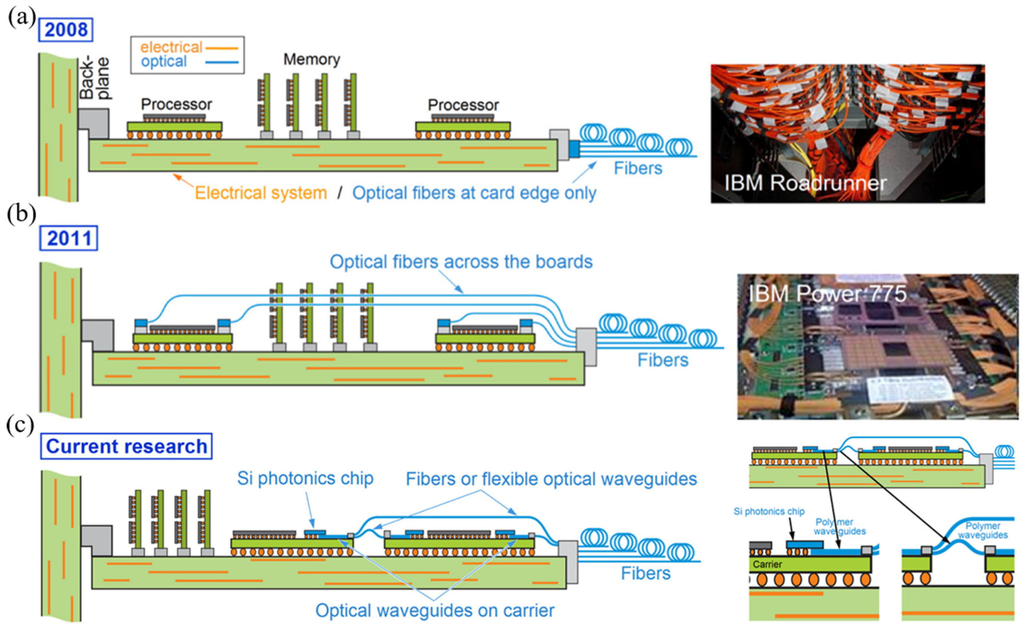
Figure 1. Photonics integration: (a) Optics at the board edge only. (b) Optical fibers across the boards. (c) The PICs on the board are interconnected with the PWB, as well as between the PICs and the edges of the board. The inset shows the use of polymer waveguides to connect Si photonic chips with the system.
Photonics 12 00821 g001
Figure 2. Fiber-to-chip coupling: (a) schematic diagram of the cross-section of single-mode optical fiber; (b) schematic of optical interconnects between fiber and Si waveguide [28]; (c) there are mainly two types of optical coupling from fiber to chip—edge couplers and grating couplers [29].
Photonics 12 00821 g002
Figure 3. Edge coupler based on spot-size converters: (a) schematic layout of the multi-tip edge coupler; (b) novel low-loss fiber-chip edge coupler.
Photonics 12 00821 g003
Figure 4. Edge coupler: (a) schematic of the two-mode multiplexer based on SWG-slot-assisted adiabatic coupler; (b) structure of the SWG metamaterial edge coupler; (c) schematic layout of the fiber-to-chip edge-coupler-assisted SWG structure.
Photonics 12 00821 g004
Figure 5. SiN platform coupler: (a) low-loss broadband bi-layer ECs—the illustration displays the cross-sectional view and the SEM diagram; (b) low-loss fiber-to-chip EC for silicon nitride integrated circuits.
Photonics 12 00821 g005
Figure 6. Schematic of highly efficient, polarization-independent EC based on LNOI.
Photonics 12 00821 g006
Figure 7. Grating coupler: (a) uniform grating coupler [43]; (b) non-uniform grating coupler [44].
Photonics 12 00821 g007
Figure 8. Photonic wire bonds: (a) architecture of optical interconnection between various optical components using photonic wire-bonding technology; (b) architecture of optical interconnection between chips using photonic wire-bonding technology.
Photonics 12 00821 g008
Figure 9. Three-Dimensional PWBs: (a) illustration of an eight-channel transmitter—the inset shows the interface between an InP laser chip and the silicon photonic transmitter chip (left) and the fiber-to-chip interface (right); (b) four-channel coherent transmitter module combining hybrid integration concepts on the chip and package levels; (c,d) an integration scheme for neural networks based on three-dimensional PWBs.
Photonics 12 00821 g009
Figure 10. Schematic of the application of PWB technology in on-chip laser technology: (a) Vision of a photonic multi-chip transmitter for WDM communications. (b) Hybrid external-cavity lasers (ECL). (c) Schematic showing the design of the laser.
Photonics 12 00821 g010
Figure 11. Research on PWB technology in extreme environments.
Photonics 12 00821 g011
Figure 12. Roadmap of transceiver: (a) pluggable transceivers; (b) OBO; (c) NPO; (d) CPO [65].
Photonics 12 00821 g012
Figure 13. Two-dimensional CPO: optical engine integration options of PIC on fan-out EIC.
Photonics 12 00821 g013
Figure 14. The 2.5D CPO: (a) 2.5D silicon photonic transmitter; (b) 2.5D CPO schematic diagram; (c) physical diagram of 2.5D CPO components; (d) a CPO packaging technology based on a photonic-wire-bonded GIP.
Photonics 12 00821 g014
Figure 15. Three-dimensional CPO: (a) a general diagram of a 3D integrated optical transceiver module; (b) schematic diagram of the 3D co-packaged transmitter optical sub-assembly.
Photonics 12 00821 g015
Figure 16. I-CubeE advanced packaging technology: (a) Samsung’s I-CubeE advanced packaging solutions; (b) the CPO platform with the I-CubeE advanced packaging technology.
Photonics 12 00821 g016
Table 1. Comparison of edge coupler parameters.
NamePlatformBandwidth (GHz)Coupling LossAlignment Tolerance
Fiber-to-chip edge coupler based on double-tip inverse tapers [31]SOI1480–1630 nm1.10 dB (TE)
1.52 dB (TM)
X ± 1.25 µm (3 dB)
Y ± 0.95 µm (3 dB)
Multi-tip edge coupler [32]SOI1260–1675 nm0.4249 dB (1550 nm)horizontal direction ± 0.77 μm (1 dB)
vertical direction ± 0.41 μm (1 dB)
Novel low-loss fiber-chip edge coupler [33]SiN1550 nm ± 50 nm0.44 dB (TE)
0.04–0.08 dB (TM)
2.8 μm
Silicon nitride spot-size converter with very low loss over the C-band [34]SiN1530–1570 nm0.18 dBN/A
Two-mode multiplexer based on subwavelength grating slot-assisted adiabatic coupler [35]SOI1260–2000 nm (simulation)
1260–1360 nm (measurement)
1500–1630 nm (measurement)
0.32 dB (simulation)
2.6 dB (measurement)
20 nm (0.76 dB)
SWG metamaterial edge coupler [36]SOI1508–1628 nm2.22 dB (TE)
2.53 dB (TM)
±10 nm
Fiber-to-chip edge coupler assisted by SWG [37]SOI240 nm0.23 dB−40–200 nm (0.5 dB)
Low-loss broadband bi-layer edge couplers [38]SiN445–640 nm4 dBX ± 0.88 µm (1 dB)
Y ± 1.15 µm (1 dB)
Low-loss fiber-to-chip edge coupler for silicon nitride integrated circuits [39]SiN1525–1630 nm0.8 dB±2 μm (1 dB)
Silicon-nitride-assisted tri-layer edge coupler [40]LNOIN/A0.64 dB±3.1 μm (0.5 dB)
Highly efficient, polarization-independent edge coupler based on LNOI [41]LNOI1527–1630 nm1 dB±1 μm (0.6 dB)
Table 2. Comparison of performance parameters of grating couplers.
NamePlatformBandwidth (GHz)Coupling Loss
Segmented-waveguide grating coupler [45]SOI71.4 nm, (covers the entire C-band)2.86 dB
Dual-layer grating coupler [46]Si-SiN34 nm (1.56 μm, TM)
49 nm (1.56 μm, TE)
47 nm (1.32 μm, TM)
4.83 dB (1.56 μm, TM)
3.87 dB (1.56 μm, TE)
5.68 dB (1.32 μm, TM)
Two-layer grating coupler [47]SOI203 nm (1540 nm, chip-to-fiber)
62 nm (1550 nm, fiber-to-chip)
0.97 dB (1540 nm, chip-to-fiber)
1.54 dB (1550 nm, fiber-to-chip)
PVBGC [43]SOI147 nm (3 dB)
121 nm (1 dB)
3.78 dB (simulation)
4.6 dB (experiment)
Nearly vertical binary blazed grating coupler [48]SOI42 nm (1 dB)
68 nm (3 dB)
90% (coupling efficiency)
Silicon grating coupler for vertical backside coupling [44]SiN20 nm (1 dB)3.97 dB
Grating couplers with metal back-reflector [49]SiN100 nm0.61 dB (TE)
0.95 dB (TM)
Disclaimer/Publisher’s Note: The statements, opinions and data contained in all publications are solely those of the individual author(s) and contributor(s) and not of MDPI and/or the editor(s). MDPI and/or the editor(s) disclaim responsibility for any injury to people or property resulting from any ideas, methods, instructions or products referred to in the content.