Article

Topological Large-Area Waveguide States Based on THz Photonic Crystals
1
Engineering Training Center, Chengdu Aeronautic Polytechnic University, Chengdu 610100, China
2
School of Physics, University of Electronic Science and Technology of China, Chengdu 611731, China
*
Authors to whom correspondence should be addressed.
Photonics 2025, 12(8), 791; https://doi.org/10.3390/photonics12080791
Submission received: 5 July 2025 / Revised: 25 July 2025 / Accepted: 30 July 2025 / Published: 5 August 2025
(This article belongs to the Section Optoelectronics and Optical Materials)

Abstract

Terahertz (THz) has attracted substantial attention owing to its unique advantages in high-speed communications. However, conventional THz waveguide systems are inherently constrained by high transmission losses, stringent fabrication precision requirements, and extreme sensitivity to structural defects. Topological edge states with topological protection have driven significant advancements in THz wave manipulation. Nevertheless, the width of the topological waveguide based on edge states remains restricted. In this work, we put forward a type of spin photonic crystal with three-layer heterostructures, where large-area topological waveguide states are demonstrated. The results show that these topological waveguide states are localized within the region of Dirac photonic crystals. They also display spin-momentum-locking characteristics and maintain strong robustness against defects and sharp bends. Furthermore, a THz beam splitter and a topological beam modulator are implemented. The designed heterostructures expand the applications of multi-functional topological devices and provide a prospective pathway for overcoming the waveguide bottleneck in THz applications.

1. Introduction

THz waves are regarded as a transformative technology for next-generation high-speed wireless communications, high-resolution security imaging, non-destructive testing, biomedical diagnostics, and fundamental materials science research, owing to their unique penetrability, spectral fingerprinting characteristics, and wide available bandwidth [1,2]. However, the practical application of THz technology has long been hampered by the absence of high-performance guided-wave devices. Existing THz waveguides, such as hollow metallic waveguides, dielectric wire waveguides, and photonic crystal waveguides, face several common and severe challenges, including high transmission loss and backscattering losses induced by waveguide structural defects, and bends are particularly pronounced in the THz frequency range, severely limiting transmission efficiency. It is noteworthy that the fundamental advantages of topological photonic insulators—inherent suppression of backscattering and robust energy transport under disorder and bending conditions—offer a highly promising solution to the critical challenges faced by the THz waveguides outlined above, particularly high scattering loss and defect sensitivity [3].
Inspired by topological insulators in electronic systems [4], topology has been introduced into electromagnetic fields. In recent years, topological photonic crystals have undergone significant development. Topological edge states have garnered substantial attention owing to their topological characteristics with strong robustness against sharp bends and defects [5]. Initially, topological photonic crystals were first realized in magnetic photonic crystal systems with an applied external magnetic field, but this approach was confined to the microwave regime [6]. Subsequently, based on the quantum spin Hall effect, spin topological insulators were realized via bianisotropic electromagnetic structures [7]. But this scheme is difficult to realize. Later, all-dielectric photonic crystals were employed to induce topological phase transitions by breaking lattice symmetry [8,9]. Analogous to the quantum valley Hall effect, valley photonic crystals were proposed by breaking spatial-inversion symmetry [10,11,12,13]. Recently, numerous topological waveguides [14,15,16,17,18,19], topological lasers [20,21,22], and other topological devices [23,24,25,26,27,28] have been demonstrated based on topological valley edge states [14,15,16,17,18,19,20,21]. According to bulk-edge correspondence, topological edge states, including chiral edge state, helical edge state, and valley edge state, mainly emerge at the interface between two topological photonic crystals with different Chern numbers [16,29]. These edge states possess good performance with one-way transmission and robustness against defects and sharp bends. However, the energy flux of these conventional edge states is limited, and the width of topological waveguide is fixed, rendering it difficult to achieve flexible manipulation of energy channels and integration with traditional waveguides. Then topological waveguides based on three-layer heterostructures were proposed in sonic crystals [30,31,32]. Recently, many kinds of topological waveguides with sandwich structures based on magnetic photonic crystals [33,34] and valley photonic crystals [35,36,37] have been proposed, and unique valley-locked and high-flux characteristics have been demonstrated. Although fundamental theories and applications of flexible electromagnetic devices and systems have been demonstrated, the flexible manipulation of electromagnetic waves via topological photonic crystals holds significant potential for THz and optical devices [38,39].
In this work, we introduce a C6-symmetric spin photonic crystal that comprises six petal-shaped dielectric scatterers per unit cell. By modulating the ratio of the lattice constant to the distance from the dielectric scatterer to the lattice center, topological phase transitions are induced, giving rise to helical edge states at the interface between topologically trivial and non-trivial domains. These states exhibit spin-momentum locking with unidirectional propagation and maintain robustness against defects, although their confinement to interfaces limits energy throughput. To address this, large-area topological waveguide states have been demonstrated in three-layer heterostructures, where Dirac photonic crystals are sandwiched between topological photonic crystals with distinct topological phases. Results show that these extended topological waveguide states are localized within the Dirac photonic crystal region. They exhibit spin-momentum-locking characteristics, with pseudospin-up and pseudospin-down waveguide states propagating unidirectionally when a chiral source is positioned at the center of the Dirac photonic crystal region. Robustness against defects and sharp bends is also confirmed. Additionally, a THz beam splitter with high-capacity energy transport has been designed using three-layer heterostructures, and a topological energy concentrator has been implemented. The topological THz waveguides with large-area waveguide states presented here hold significant promise for advancing terahertz (THz) applications requiring robust waveguiding. Recent developments highlight the critical role of THz systems in diverse fields, such as non-invasive biological sensing [40] and mineral characterization [41]. The flexible topological waveguides proposed in this work offer a natural interface for such systems, providing bend tolerance and signal integrity essential for conformable sensing platforms and probing irregular sample geometries. Furthermore, the spin-locked waveguide states revealed in this study hold broader implications for guided-wave photonics. Their control mechanisms may pioneer new paradigms for manipulating bright–dark pulse interactions in photonic crystal fibers [42], potentially enabling enhanced signal processing capabilities in conventional waveguiding platforms.

2. Heterostructure-Based Structure and Band Structure Analysis of Unit Cell

The designed heterostructure is composed of three distinct domains, namely domain A, domain B, and domain C, as illustrated in Figure 1a. Each domain is fabricated from C6-symmetric photonic crystals, denoted as PC1, DPC, and PC2, respectively. These photonic crystals share an identical lattice constant a = 300 µm. Micrometer-scale periodic structures (10–1000 µm) are routinely fabricated using established techniques such as photolithography, laser direct writing, and 3D printing—all of which offer sufficient precision to replicate the lattice geometry and unit-cell dimensions in our simulations [43,44]. Among the proposed platforms, high-resistivity silicon is strongly recommended due to its precision, loss characteristics, and process maturity for 300 µm-scale fabrication. For microwave and THz devices, high-resistivity silicon serves as the substrate of choice for patterning precision periodic lattices [28]. As depicted in Figure 1b, the unit cell of each photonic crystal is constructed by six petal-shaped dielectric scatterers, which are arranged based on three circular dielectric scatterers with r = 0.05a, O1O2 = 3 r, and the dielectric constant is 11.7. The distance from the center of the petal-shaped scatter to the center of the hexagon is R, which is different for each PC. For PC1, DPC, and PC2, the ratios a/R are 2.7, 3, and 3.5, respectively. DPC represents a standard honeycomb-structured photonic crystal, whereas PC1 exhibits an expanded lattice configuration, and PC2 features a contracted lattice structure. Here, the finite-element software COMSOL Multiphysics 5.6 is employed to solve the eigen equations to obtain the band structure of the PCs. In this study, only the transverse magnetic (TM) mode is considered, which comprises out-of-plane electric field component Ez and in-plane magnetic field components Hx and Hy, with all other field components being zero. According to Maxwell’s equation, the eigenvalue equation can be formulated as follows:
× c 2 ε ( r ) × E ( r ) = ω 2 E ( r )
where ε(r) is the position-dependent permittivity, E(r) is the position-dependent electric field vector, c is the speed of light in vacuum, and ω is the angular frequency of the electromagnetic wave. The band structures of DPC, PC2, and PC1 are presented in Figure 1c, Figure 1d, and Figure 1e, respectively. When a/R = 3, due to the preservation of C6-symmetry in the unit cell, a four-fold degenerate Dirac cone emerges at the frequency of 0.5769 THz. To achieve a complete photonic bandgap, symmetry breaking can be induced by altering the ratio a/R. When a/R = 3.5, the four-fold degenerate Dirac cone is disrupted, leading to the formation of a complete photonic bandgap, which spans from 0.5471 THz to 0.6190 THz. From the band structure diagram of PC2 shown in Figure 1c, it is evident that the d-like energy states are positioned above the p-like energy states. Figure 1f displays the Ez field distributions corresponding to the eigenstates px, py, dx2−y2, and dxy. Based on these characteristics, PC2 can be classified as a trivial topological photonic crystal. Conversely, when a/R = 2.7, as indicated by the band structure of PC1 in Figure 2d, there also exists a complete bandgap from 0.5453 THz to 0.6176 THz. However, the p states are above the d states, suggesting that PC1 can be regarded as a non-trivial topological photonic crystal. Consequently, PC1 and PC2 exhibit distinct topological phases, and a topological phase transition takes place as the ratio a/R varies from 2.7 to 3.5. In principle, the proposed design can be scaled to the target frequency bands. The key to maintaining topological protection lies in the proper adjustment of the geometric parameters of the structure. As the frequency increases, the lattice constant, a, needs to be reduced proportionally. If the original center frequency is f0 and the corresponding lattice constant is a, according to the scaling law, the new lattice constant a1 for the target frequency f1 in this band can be calculated by a1 = a0 × f0/f1. However, as the lattice constant becomes smaller, the precision requirements for the fabrication process increase significantly. The impact of material imperfections on the structure’s performance increases significantly.

3. Topological Edge States and Topological Large-Area Waveguide States

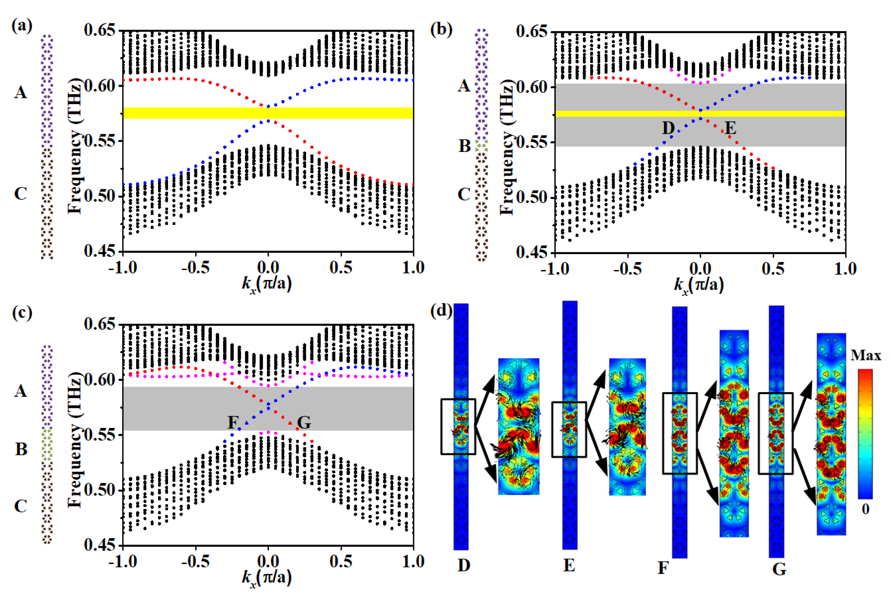
In accordance with the bulk-edge correspondence principle, topological edge states exist at the interface between two domains with distinct topological phases. To verify the existence of these topological edge states, a supercell configuration composed of PC1 and PC3 is constructed. To compute the band diagrams of the supercell, we defined two distinct boundary conditions: periodic boundaries along the x-axis and scattering boundaries along the y-axis. The scattering boundaries effectively absorb y-direction electromagnetic wave leakage from the computational domain, eliminating reflected wave interference to ensure extraction of the structure’s intrinsic propagating modes. As shown in Figure 2a, within the bulk bandgap of this supercell, two branches of helical edge states emerge. Here, the red dots represent pseudospin-up states, while the blue dots signify pseudospin-down states. However, an observable small bandgap (highlighted by the yellow region) exists between the upper and lower boundary states. This phenomenon is attributed to the breaking of C6 symmetry at the supercell interface. Notably, as the magnitude of the perturbation increases, the width of this bandgap also expands proportionally. Leveraging the aforementioned photonic crystals (PCs), an ABxC-type supercell with x = 1 of domain B is proposed, as illustrated in Figure 2b. Through analyzing the band structure of the designed heterostructure, it is revealed that a pair of helical topological states also exist, with a minor gap separating them. Additionally, Figure 2d presents the electric field and Poynting vector distributions of the helical eigenstates with a frequency of 0.560 THz at kx = 0.15π/a near the Γ point, labeled with D (denoted by the blue five-pointed star) and E (denoted by the red five-pointed star). It is evident that the electric energy is predominantly confined within domain B, which distinguishes these states from conventional topological edge states. Specifically, the eigenstate D, at kx = −0.15π/a, exhibits a clockwise characteristic, resulting in upward energy propagation, whereas the eigenstate E, at kx = 0.15π/a, shows a counterclockwise characteristic, leading to downward energy propagation. These states also display spin-locked characteristics and can be classified as topological large-area waveguide states. A small bandgap (marked in yellow) is observed between the two branches of these topological large-area waveguide states, where the blue dotted lines denote the spin-up waveguide states and the red dotted lines represent the spin-down waveguide states. Compared with the band structure of the AC-type supercell, the width of this small gap is reduced. Although other waveguide states (marked in pink) are present, they are non-topological states and can not have topological characteristics. Furthermore, as depicted in Figure 2c, the dispersion relation of the heterostructure AB3C is also investigated. Taking a pair of eigenstates labeled F and G as an example, they share the same frequency of 0.561 THz at kx = 0.15π/a. Their electric field intensity and Poynting vector distributions, as shown in Figure 2d, indicate that the electric energy is primarily distributed within domain B, and these states possess opposite group velocities. This further validates that these topological large-area waveguide states exhibit the unique spin-locked property. It is noted that the topological frequency window (indicated by the gray area) decreases as the number of layers of domain B increases. This occurs because the thicker Domain B acts as a more effective spacer. It increases the physical separation between the interface modes (confined to the interfaces between A|B and B|C) and the bulk states (within the domain B). This increased separation further weakens the already minimal coupling between these two types of states. Consequently, interface modes become more strongly confined and localized to their interface, and they do not significantly hybridize with or leak energy into the bulk states of the adjacent domains, which restricts the range of frequencies over which they can propagate effectively, thereby shrinking the topological frequency window. Moreover, as the value of x increases, the small gap between the topological large-area waveguide states becomes narrower. This is because the insertion of domain B reduces the degree of symmetry mismatch between domains A and C. Domains A and C inherently possess different symmetries. This difference in symmetry (symmetry mismatch) creates a significant barrier or discontinuity at their interface. Domain B is inserted between domains A and C. Its purpose is to act as a transitional region (buffer). It provides a smoother transition from the symmetrical properties of Domain A to those of Domain C. This reduces the overall symmetry mismatch felt across the structure from A to C. As x increases (making Domain B larger or more effective), the symmetry transition becomes even smoother. A smoother symmetry transition means the boundary conditions experienced by the topological waveguide states become less abrupt. This reduced discontinuity allows the paired topological states to interact more strongly or brings their energies closer together. Consequently, the energy separation (the gap) between these specific topological states decreases (narrows) as x increases and the symmetry mismatch reduces. Apart from the topological larger-area waveguide states, non-topological waveguide states (denoted by the pink dots) also appear at bulk bandgaps.
Figure 2. (a) Configuration of the supercell, the unit cells PC1 are placed at the upper domain, and the unit cells PC2 are located at the lower domain. The dispersion diagram of the supercell AC where the blue dots represent the spin-up edge states and the red dots represent the spin-down states. (b) The dispersion diagram of the supercell ABC. The red dot A represents the spin-up edge state, and the blue dot B represents the spin-down state. (c) The dispersion diagram of the supercell AB3C. (d) The electric field distributions and Poynting vectors of waveguide states labeled as D, E, F, and G, where the black arrows represent the Poynting vector.
Photonics 12 00791 g002

4. Spin-Momentum-Locking and Robustness Analysis of Topological Large-Area Waveguide States

To investigate the transmission characteristics of topological large-area waveguide states, a straight waveguide with a sandwich structure is constructed, as illustrated in Figure 3a. A harmonic source, marked by a red star, is positioned at the center of domain B composed of Dirac photonic crystals (PhCs). A harmonic source with the frequency of 0.57 THz is composed of four-line sources with a π/2 phase increase in the clockwise direction. This source carries a negative orbital angular momentum (OAM) and is capable of exciting the pseudo-spin-up state. In practical implementations, a square array consisting of four antennas can be employed to excite pseudospin-up or pseudospin-down modes, the initial phase should decrease or increase clockwise by π/2 between adjacent antennas. This four-antenna array is driven by a one-to-four power divider, ensuring that each antenna emits energy uniformly. To introduce phase delays between the antennas, four coaxial cables of varying lengths are employed to connect the antennas to the SMA output ports of the power divider. As observed from the electric field distributions in Figure 1a, the electromagnetic (EM) wave propagates unidirectionally towards the right port. Conversely, when the harmonic source is composed of four-line sources with a π/2 phase increase in the counterclockwise direction, which carries positive OAM and can excite the pseudo-spin-down state, as shown in Figure 3b, the EM wave still propagates unidirectionally, but toward the left port. Additionally, the EM wave energy is predominantly confined within domain B and decays rapidly along both the +y and −y directions. These results effectively demonstrate the unidirectionality of the large-area waveguide states and their spin-momentum-locking characteristics. Due to the spin-momentum-locking property, the proposed topological waveguide with a heterostructure can exhibit strong robustness to sharp bends and defects. In order to verify them, three types of waveguides are introduced, as shown in Figure 3c–e. An Ω-shaped waveguide is constructed based on the above heterostructure. There are four sharp bends along the waveguide channel. A chiral source with the frequency of 0.57 THz is placed near the left port and the EM wave can propagate smoothly through the sharp bends with negligible reflection. As illustrated in Figure 3f, the transmission coefficient further confirms that the large-area waveguide states from 0.556 THz to 0.590 THz are strong against sharp bending and possess topological properties. Additionally, to assess the immunity of these large-area waveguide states to structural imperfections and disorder, artificial defects and random perturbations are introduced into a straight waveguide. As illustrated in Figure 3d, when a unit cell is removed from domain B (as indicated in the inset), the EM waves experience local disturbances around the defect but rapidly recover their original propagation characteristics after passing through the defective region. Moreover, as shown in Figure 3e, two unit cells of type PC1 are replaced by two unit cells of type PC2 within the waveguide channel, which does not impede the smooth propagation of EM waves. The field distributions remain essentially unchanged before and after the structural modification. The simulated transmission coefficients of three waveguide structures are also presented in Figure 3e, which reveals that in the absence of medium losses, the transmission efficiency approaches 100% within the operational band of 0.556–0.590 THz. These findings conclusively demonstrate that the proposed heterostructured waveguide supports large-area topological modes, which are characterized by topological protection and exhibit robust transmission against sharp bends, defects, and disorders. Herein, the effect of high-resistivity silicon loss on the wave propagation property in the proposed photonic crystals is studied. The dielectric loss tangent (tanδ) of high-resistivity silicon in the 0.55–0.60 THz range has been experimentally characterized in multiple studies [45]. We assume that the loss tangent of high-resistivity silicon at 0.57 THz is approximately 3.6 × 10⁻⁴. As shown in Figure 3e, the transmission curve of the Ω-shaped waveguide with loss is also plotted. At 0.57 THz, the transmission coefficient decreases to 0.822. Compared with the lossless-case reference value of 0.999, this yields a 0.846 dB reduction in the S21 transmission parameter. The observed attenuation is therefore predominantly attributable to dielectric loss mechanisms.

5. Application of Topological Large-Area Waveguide States

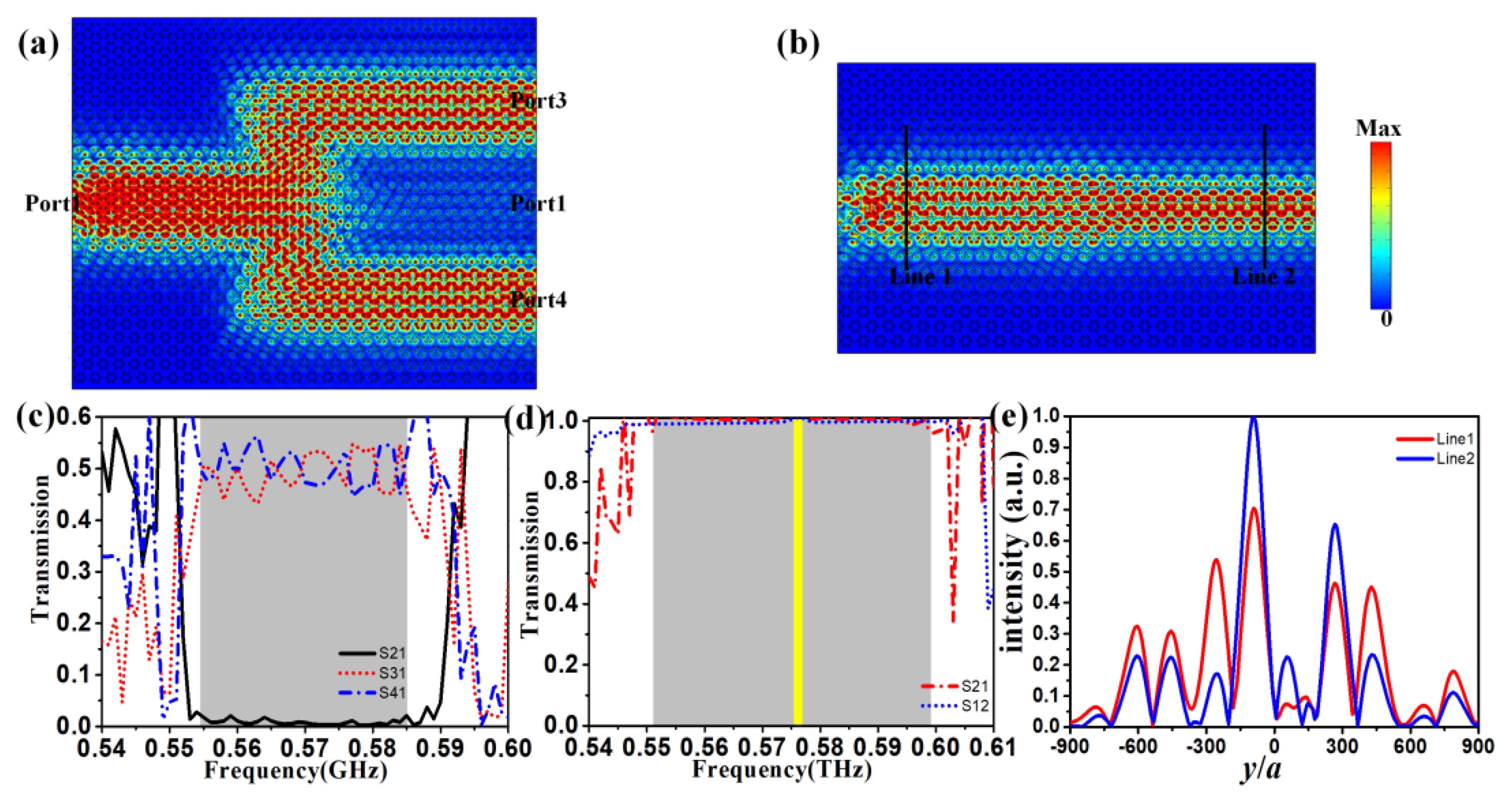
Topological large-area waveguide states with unique transmission behaviors can be considered an excellent platform to realize various topological devices such as topological power dividers and topological beam modulators. First, a spin-locked topological power divider is designed based on the heterostructure. As shown in Figure 4a, the divider consists of five different parts and there are four ports labeled as Port 1, Port 2, Port 3, and Port 4. Port 1 and Port 2 have different spin pseudospins and are located on the straight transmission route, while Port 3 and Port 4 have the same spin pseudospin as Port 1 and are located on two zigzag transmission routes with 120° sharp bends. A chiral source with a negative OAM (denoted by the red star) is placed near Port 1, as shown in Figure 4a. The excited spin-up waveguide states can reach the ports with the same spin pseudospin. Then, EM propagates smoothly through sharp bends and reaches Port 3 and Port 4, instead of going straight into Port 2 because of the spin-momentum-locking property. From the electric field distributions, it can be seen that the EM energy is mainly confined at domain B and the topological large-area states exhibit strong robustness against sharp bends. To quantitatively evaluate and compare the transmission characteristics of the topological large-area waveguide states, four power flow monitors are positioned at the respective reference planes (denoted as S1, S2, S3, and S4), perpendicular to the waveguide channel. By integrating the Poynting vector over these planes, the total transmitted power at each port is obtained. Subsequently, the transmission coefficients S21 (Port 1 → Port 2), S31 (Port 1 → Port 3), and S41 (Port 1 → Port 4) are derived and shown in Figure 4c. The simulated transmission spectra reveals that S21 and S31 are significantly higher than S41 within the topological bandgap (shaded in gray), which arises from the spin-momentum-locking effect. Specifically, the propagation direction of the topological large-area waveguide is intrinsically tied to their spin pseudospin degree of freedom, ensuring unidirectional transmission along predetermined paths. Consequently, the system exhibits spin-selective routing, where energy preferentially couples to Port 2 and Port 3 while being strongly suppressed at Port 4.
Next, based on the heterostructure, a topological beam modulator shown in Figure 4b is designed and is capable of compressing or expanding optical beam width. In the device architecture, the beam modulator comprises a wider waveguide and a narrower waveguide, where the number of layers in domain B abruptly changes from three to one, from left to right. In order to excite topological waveguide states, a chiral source is placed at the left port of the wider waveguide. From the electric field distributions at 0.57 THz, EM propagates rightward with a wider beam of three layers in the left part, then is compressed to a narrower beam with a single layer, functioning as a beam compressor. Conversely, the EM wave excited by the pseudospin-down source propagates leftward, serving as a beam expander. The corresponding energy intensity profiles along the red and blue reference lines are presented in Figure 4e. These results clearly demonstrate that the energy density exhibits significant reduction (or enhancement) when the electromagnetic wave propagates rightward (or leftward). Furthermore, Figure 4d displays the transmission spectra of the beam modulator, where S21 denotes the transmission coefficient from Port 1 to Port 2, and S12 denotes the transmission coefficient from Port 2 to Port 1, confirming that the topological larger-area waveguide state within the topological bandgap (shaded in gray) maintains robust topological unidirectional propagation characteristics during both the beam compression and expansion processes. This tunable device provides a promising technical approach for energy transmission modulation in photonic-integrated devices.

6. Discussion and Conclusions

The reported works mainly pay more attention to one dimensional topological edge states. Helical chiral edge states exist at the interface between topologically trivial and non-trivial domains. However, the modal confinement effect in conventional edge-state waveguides severely limits their effective waveguide width, which significantly constrains their potential for high-capacity energy transport applications. Recently, some topological large-area waveguides have been proposed. But they have only been demonstrated in the lower bands. A comparison between our work and other relevant topological large-area waveguides reported in the literature is listed in Table 1. In this work, topological large-area waveguides with spin-locking in the THz band are achieved within an all-dielectric structure without magnetic fields, significantly enhancing energy localization and throughput. Strong spin-momentum locking is realized through geometric parameter modulation, eliminating the need for external fields or complex anisotropic materials.
In conclusion, we propose a spin photonic crystal structure based on C6-symmetric unit cells, with each cell consisting of six petal-shaped dielectric scatterers. Topological phase transitions are engineered by controlling the geometric parameter ratio (specifically, adjusting the ratio of lattice constant to the distance from the dielectric scatter to the center of the lattice). Then we have developed a three-layer heterostructure, where Dirac photonic crystals are sandwiched between two topological photonic crystals with distinct topological phases. Simulated results demonstrate that this novel architecture supports extensively localized topological waveguide states that are strictly confined within the Dirac photonic crystal domains. When excited by a chiral point source, the system selectively activates pseudospin-up/down waveguide modes, enabling backscattering-free unidirectional propagation in opposite directions while perfectly maintaining spin-momentum locking characteristics. The results further confirm that these extended states exhibit strong robustness against various structural defects and sharp bends. Based on three-layer heterostructures, we have successfully developed two important functional devices: a high-performance terahertz beam splitter with high energy transport capacity, and a novel topological energy concentrator capable of achieving energy enhancement. These innovative heterostructures not only significantly expand the functional dimensions of topological photonic devices but also provide a groundbreaking technological pathway for high-performance integrated devices in the terahertz regime (including topological sensors, filters, and optical switches). This work paves the way for the practical implementation of topological photonic integrated circuits.

Author Contributions

Methodology, Y.Z. and F.L.; software, Y.Z. and J.H.; validation, H.H., J.L., J.C., K.Z. and Y.Y.; writing—original draft preparation, Y.Z. and F.L. All authors have read and agreed to the published version of the manuscript.

Funding

This work was supported by Science Foundation of Chengdu Aeronautic Polytechnic University (ZZX0624081), Key Laboratory of Interior Layout Optimization and Security, Institutions of Higher Education of Sichuan Province, Chengdu Normal University, China (SNKJ202407), and China Postdoctoral Science Foundation (2024M764271).

Data Availability Statement

Data are contained within the article.

Conflicts of Interest

The authors declare no conflicts of interest.

References

  1. Leitenstorfer, A.; Moskalenko, A.S.; Kampfrath, T.; Kono, J.; Castro-Camus, E.; Peng, K.; Qureshi, N.; Turchinovich, D.; Tanaka, K.; Markelz, A.G.; et al. The 2023 terahertz science and technology roadmap. J. Phys. D Appl. Phys. 2023, 56, 223001. [Google Scholar] [CrossRef]
  2. Jiang, W.; Guerboukha, H.; Jornet, J.M.; Mittleman, D.M.; Yang, Z. Terahertz Communications and Sensing for 6G and Beyond: A Comprehensive Review. IEEE Commun. Surv. Tutor. 2024, 26, 2326–2381. [Google Scholar] [CrossRef]
  3. Kumar, A.; Gupta, M.; Pitchappa, P.; Wang, N.; Fujita, M.; Singh, R. Terahertz Topological Photonic Integrated Circuits for 6G and Beyond: A Perspective. J. Appl. Phys. 2022, 132, 140401. [Google Scholar] [CrossRef]
  4. Hasan, M.Z.; Kane, C.L. Colloquium: Topological insulators. Rev. Mod. Phys. 2010, 82, 3045–3067. [Google Scholar] [CrossRef]
  5. Lu, L.; Joannopoulos, J.D.; Soljačić, M. Topological photonics. Nat. Photonics 2014, 8, 821–829. [Google Scholar] [CrossRef]
  6. Haldane, F.D.M.; Raghu, S. Possible Realization of Directional Optical Waveguides in Photonic Crystals with Broken Time-Reversal Symmetry. Phys. Rev. Lett. 2008, 100, 013904. [Google Scholar] [CrossRef]
  7. Khanikaev, A.B.; Mousavi, S.H.; Tse, W.K.; Kargarian, M.; MacDonald, A.H.; Shvets, G. Photonic topological insulators. Nat. Mater. 2013, 12, 233–239. [Google Scholar] [CrossRef]
  8. Wu, L.H.; Hu, X. Scheme for Achieving a Topological Photonic Crystal by Using Dielectric Material. Phys. Rev. Lett. 2015, 114, 223901. [Google Scholar] [CrossRef]
  9. Yang, Y.T.; Xu, Y.F.; Xu, T.; Wang, H.X.; Jiang, J.H.; Hu, X.; Hang, Z.H. Visualization of a unidirectional electromagnetic waveguide using topological photonic crystals made of dielectric materials. Phys. Rev. Lett. 2018, 120, 217401. [Google Scholar] [CrossRef] [PubMed]
  10. Ma, T.; Shvets, G. All-Si valley-Hall photonic topological insulator. New J. Phys. 2016, 18, 025012. [Google Scholar] [CrossRef]
  11. Dong, J.W.; Chen, X.D.; Zhu, H.; Wang, Y.; Zhang, X. Valley photonic crystals for control of spin and topology. Nat. Mater. 2017, 16, 298–302. [Google Scholar] [CrossRef]
  12. Chen, X.D.; Zhao, F.L.; Chen, M.; Dong, J.W. Valley-contrasting physics in all-dielectric photonic crystals: Orbital angular momentum and topological propagation. Phys. Rev. B 2017, 96, 020202. [Google Scholar] [CrossRef]
  13. Gao, F.; Xue, H.R.; Yang, Z.J.; Lai, K.F.; Yu, Y.; Lin, X.; Chong, Y.D.; Shvets, G.; Zhang, B.L. Topologically protected refraction of robust kink states in valley photonic crystals. Nat. Phys. 2018, 14, 140–144. [Google Scholar] [CrossRef]
  14. He, X.T.; Liang, E.T.; Yuan, J.J.; Qiu, H.Y.; Chen, X.D.; Zhao, F.L.; Dong, J.W. A Silicon-on-Insulator Slab for Topological Valley Transport. Nat. Commun. 2019, 10, 872. [Google Scholar] [CrossRef]
  15. Yang, Y.; Yamagami, Y.; Yu, X.; Pitchappa, P.; Webber, J.; Zhang, B.; Fujita, M.; Nagatsuma, T.; Singh, R. Terahertz topological photonics for on-chip communication. Nat. Photonics 2020, 14, 446–451. [Google Scholar] [CrossRef]
  16. Tang, G.J.; He, X.T.; Shi, F.L.; Liu, J.W.; Chen, X.D.; Dong, J.W. Topological Photonic Crystals: Physics, Designs, and Applications. Laser Photonics Rev. 2022, 16, 2100300. [Google Scholar] [CrossRef]
  17. Ma, J.; Xi, X.; Sun, X. Topological Photonic Integrated Circuits Based on Valley Kink States. Laser Photonics Rev. 2019, 13, 1900087. [Google Scholar] [CrossRef]
  18. Yoshimi, H.; Yamaguchi, T.; Ota, Y.; Arakawa, Y.; Iwamoto, S. Slow light waveguides in topological valley photonic crystals. Opt. Lett. 2020, 45, 2648–2651. [Google Scholar] [CrossRef] [PubMed]
  19. Gao, Z.; Yang, Z.; Gao, F.; Xue, H.; Yang, Y.; Dong, J.; Zhang, B. Valley surface-wave photonic crystal and its bulk/edge transport. Phys. Rev. B 2017, 96, 201402. [Google Scholar] [CrossRef]
  20. Noh, W.; Nasari, H.; Kim, H.-M.; Le-Van, Q.; Jia, Z.; Huang, C.-H.; Kante, B. Experimental demonstration of single-mode topological valley-Hall lasing at telecommunication wavelength controlled by the degree of asymmetry. Opt. Lett. 2020, 45, 4108–4111. [Google Scholar] [CrossRef] [PubMed]
  21. Zeng, Y.; Chattopadhyay, U.; Zhu, B.; Qiang, B.; Li, J.; Jin, Y.; Li, L.; Davies, A.G.; Linfield, E.H.; Zhang, B.; et al. Electrically pumped topological laser with valley edge modes. Nature 2020, 578, 246–250. [Google Scholar] [CrossRef] [PubMed]
  22. Gong, Y.K.; Wong, S.; Bennett, A.J.; Huffaker, D.L.; Oh, S.S. Topological Insulator Laser Using Valley-Hall Photonic Crystals. ACS Photonics 2020, 7, 2089–2097. [Google Scholar] [CrossRef]
  23. Wei, G.C.; Liu, Z.Z.; Zhang, D.S.; Xiao, J.J. Frequency dependent wave routing based on dual-band valley-Hall topological photonic crystal. New J. Phys. 2021, 23, 023029. [Google Scholar] [CrossRef]
  24. Kumar, A.; Gupta, M.; Pitchappa, P.; Tan, Y.J.; Wang, N.; Singh, R. Topological sensor on a silicon chip. Appl. Phys. Lett. 2022, 121, 011101. [Google Scholar] [CrossRef]
  25. Shalaev, M.I.; Walasik, W.; Litchinitser, N.M. Optically tunable topological photonic crystal. Optica 2019, 6, 839–844. [Google Scholar] [CrossRef]
  26. He, L.; Zhang, W.; Zhang, X. Topological all-optical logic gates based on two-dimensional photonic crystals. Opt. Express 2019, 27, 25841–25859. [Google Scholar] [CrossRef]
  27. Kumar, A.; Gupta, M.; Pitchappa, P.; Tan, T.C.; Chattopadhyay, U.; Ducournau, G.; Wang, N.; Chong, Y.; Singh, R. Active Ultrahigh-Q (0.2 × 10⁶) THz Topological Cavities on a Chip. Adv. Mater. 2022, 34, 2202370. [Google Scholar] [CrossRef]
  28. Kumar, A.; Gupta, M.; Pitchappa, P.; Wang, N.; Szriftgiser, P.; Ducournau, G.; Singh, R. Phototunable chip-scale topological photonics: 160 Gbps waveguide and demultiplexer for THz 6G communication. Nat. Commun. 2022, 13, 5404. [Google Scholar] [CrossRef]
  29. Rosiek, C.A.; Arregui, G.; Vladimirova, A.; Albrechtsen, M.; Vosoughi Lahijani, B.; Christiansen, R.E.; Stobbe, S. Observation of strong backscattering in valley-hall photonic topological interface modes. Nat. Photonics 2023, 17, 386–392. [Google Scholar] [CrossRef]
  30. Wang, M.; Yang, Y.; Yang, Y.T.; Li, G.Y.; Lu, M.H. Valley-locked waveguide transport in acoustic heterostructures. Nat. Commun. 2020, 11, 3000. [Google Scholar] [CrossRef]
  31. Wang, J.Q.; Liu, S.B.; Xue, H.R.; Chong, Y.D. Extended topological valley-locked surface acoustic waves. Nat. Commun. 2022, 13, 1324. [Google Scholar] [CrossRef] [PubMed]
  32. Yin, S.; Li, F.; Yang, Z.J.; Zhang, X. Acoustic valley-locked waveguides in heterostructures of a square lattice. Phys. Rev. Appl. 2022, 18, 054073. [Google Scholar] [CrossRef]
  33. Wang, M.; Hang, Z.H.; Mei, J.; Wu, Y.; Chan, C.T. Topological one-way large-area waveguide states in magnetic photonic crystals. Phys. Rev. Lett. 2021, 126, 067401. [Google Scholar] [CrossRef] [PubMed]
  34. Yu, X.; Lin, Z.K.; Wang, H.X.; Jiang, J.H. Topological large-area one-way transmission in pseudospin-field-dependent waveguides using magneto-optical photonic crystals. Photon. Res. 2023, 11, 1105–1112. [Google Scholar] [CrossRef]
  35. Chen, Q.; Xiao, J.J.; Chen, X.D.; Chen, W.J.; Li, Y. Photonic topological valley-locked waveguides. ACS Photonics 2021, 8, 1400–1406. [Google Scholar] [CrossRef]
  36. Yan, S.; Zhao, D.; Yang, Y.H.; Zhang, B.L. Transport of a topologically protected photonic waveguide on-chip. Photon. Res. 2023, 11, 1021–1028. [Google Scholar] [CrossRef]
  37. Guo, P.-Y.; Li, W.; Hu, J.; Wang, H.-X. Dual-Band Topological Large-Area Waveguide Transport in Photonic Heterostructures. Phys. Rev. B 2024, 110, 035405. [Google Scholar] [CrossRef]
  38. Liu, C.; Yang, F.; Xu, S.; Li, M. Reconfigurable Metasurface: A Systematic Categorization and Recent Advances. Electromagn. Sci. 2023, 1, 0040021. [Google Scholar] [CrossRef]
  39. Ma, K. Regulation and Control of Electromagnetic Field in Radio-Frequency Circuits and Systems. Electromagn. Sci. 2023, 1, 0030101. [Google Scholar] [CrossRef]
  40. Liu, Y.; Zhang, B.; Zhang, Y. Electronically Controlled Broadband Terahertz Amplitude Modulator Based on Ionic Liquid/PEDOT: PSS: DMSO Composite Structure. J. Opt. Photonics Res. 2024, 2, 111–117. [Google Scholar] [CrossRef]
  41. Huang, H.; Liu, Z.; Ruggiero, M.T.; Zheng, Z.; Qiu, K.; Li, S.; Zhang, Z.; Zhang, Z. Terahertz Geoscience: THz Time-Domain Spectroscopy for Mineral Materials. Cryst. Growth Des. 2025, 25, 3578–3594. [Google Scholar] [CrossRef]
  42. Al-Taie, M.S.J. The Mutual Support between Bright and Dark Pulses in Photonic Crystal Fibers. J. Opt. Photonics Res. 2025, in press. [Google Scholar] [CrossRef]
  43. Liu, K.; Jiang, Y.; Wang, Z.; Yu, X.; Li, Y.; Wang, J.; Zhang, Y.; Wei, X.; Chen, S.; Zhao, Y.; et al. 3D Printing Colloidal Crystal Microstructures via Sacrificial-Scaffold-Mediated Two-Photon Lithography. Nat. Commun. 2022, 13, 4567. [Google Scholar] [CrossRef] [PubMed]
  44. Zhu, H.-T.; Xue, Q.; Hui, J.-N.; Pang, S.W. A 750–1000 GHz H-Plane Dielectric Horn Based on Silicon Technology. IEEE Trans. Antennas Propag. 2016, 64, 5074–5083. [Google Scholar] [CrossRef]
  45. Chudpooti, N.; Duangrit, N.; Burnett, A.D.; Freeman, J.R.; Gill, T.B.; Phongcharoenpanich, C.; Imberg, U.; Torrungrueng, D.; Akkaraekthalin, P.; Robertson, I.D.; et al. Wideband Dielectric Properties of Silicon and Glass Substrates for Terahertz Integrated Circuits and Microsystems. Mater. Res. Express 2021, 8, 056301. [Google Scholar] [CrossRef]
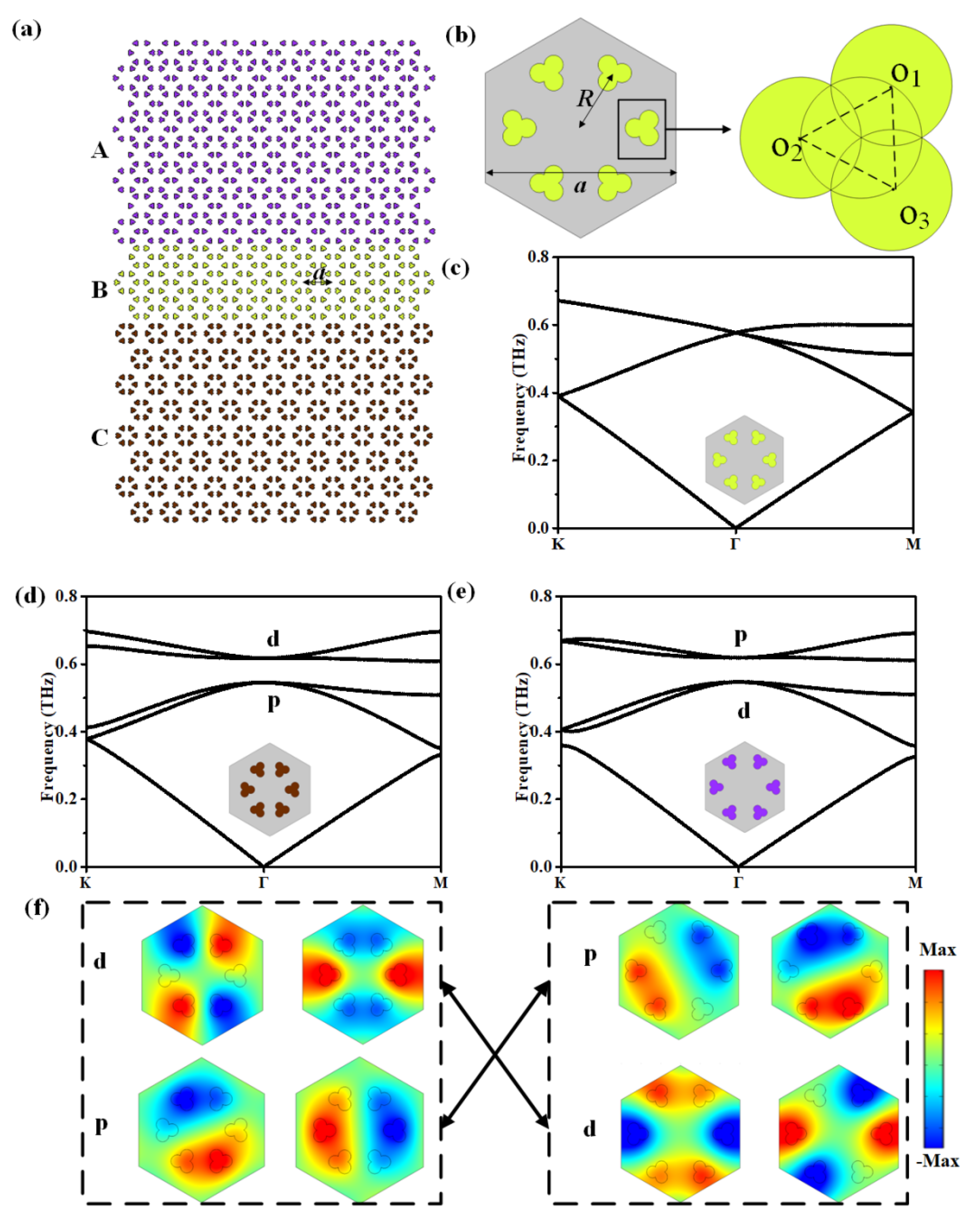
Figure 1. (a) Schematic of the designed heterostructure, composed of domain A, domain B, and domain C. (b) Schematic of the unit cell. (c) Calculated band structures of PC when R = a/3. (d,e) Dispersion relations of the structures of PC2 and PC1, respectively. (f) The distributions of electric field intensities of eigenstates near the Dirac cone for PC2 and PC1, and the process of topological phase transition.
Photonics 12 00791 g001
Figure 3. (a,b) The straight waveguide and simulated electric field intensity distributions when placing an RCP and LCP chiral source at the center of the straight path with the frequency of 0.57 THz. The black star denotes the chiral source. (c) The scheme of Ω-shaped waveguide and simulated electric field intensity distributions with the frequency of 0.57 THz. There are two flow monitors at the two reference planes (denoted by S1 and S2) vertical to the waveguide channel. (d) The straight waveguide with defects at domain B and the electric field distributions of the topological larger-area waveguide states with the frequency of 0.57 THz; the inset clearly shows the defects. (e) The straight waveguide with disorders at domain B and the electric field distributions of the topological larger-area waveguide states with the frequency of 0.57 THz; the inset clearly shows the defects. (f) Simulated transmission curves for the paths in (ce), where the gray region represents the bandgap.
Photonics 12 00791 g003
Figure 4. (a) The scheme of topological power divider and simulated electric field intensity distributions with the frequency of 0.57 THz. (b) The scheme of topological beam modulator and simulated electric field intensity distributions with the frequency of 0.57 THz. There are two flow monitors at the two reference planes (denoted by Line 1 and Line 2). (c) The transmission coefficients S21, S31, and S41. (d) The corresponding energy intensity profiles along Line 1 and Line 2. (e) The transmission spectra of the beam modulator.
Photonics 12 00791 g004
Table 1. A comparison between our work and other relevant circulators.
ReferenceArray StructureWorking FrequencyWave Transport StatesMagnetic Fields
33Magnetic rodsGHzTwo orthogonal one-way waveguide statesYes
34Magnetic rodsGHzLarge-area transport states with pseudospin-field-momentum-lockingYes
35MetasurfaceGHzTopological large-area transport states with valley-momentum-lockingNo
36Triangular airholesNear-InfraredTopological large-area transport states with valley-momentum-lockingNo
This workPetal-shaped dielectric scatterersTHzTopological large-area transport states with pseudospin-momentum-lockingNo
Disclaimer/Publisher’s Note: The statements, opinions and data contained in all publications are solely those of the individual author(s) and contributor(s) and not of MDPI and/or the editor(s). MDPI and/or the editor(s) disclaim responsibility for any injury to people or property resulting from any ideas, methods, instructions or products referred to in the content.