LEDs for Underwater Optical Wireless Communication


Abstract
1. Introduction
- Limited bandwidth, resulting in low data transmission rates;
- High latency, resulting in the relatively low speed of sound in water;
- Multipath propagation, where reflections from the sea surface, seabed, and underwater objects cause interference and/or signal distortion;
- Disclosure and jamming vulnerability, as acoustic signals can be detected and interrupted relatively easily;
- High power consumption, as acoustic systems typically require a significant amount of power to operate.
- (1)
- red light sources (LEDs and laser diodes) are widely available, featuring a higher modulation bandwidth compared to blue-green light sources, and they are significantly less expensive;
- (2)
- conventional silicon photodetectors also exhibit higher sensitivity to red light.
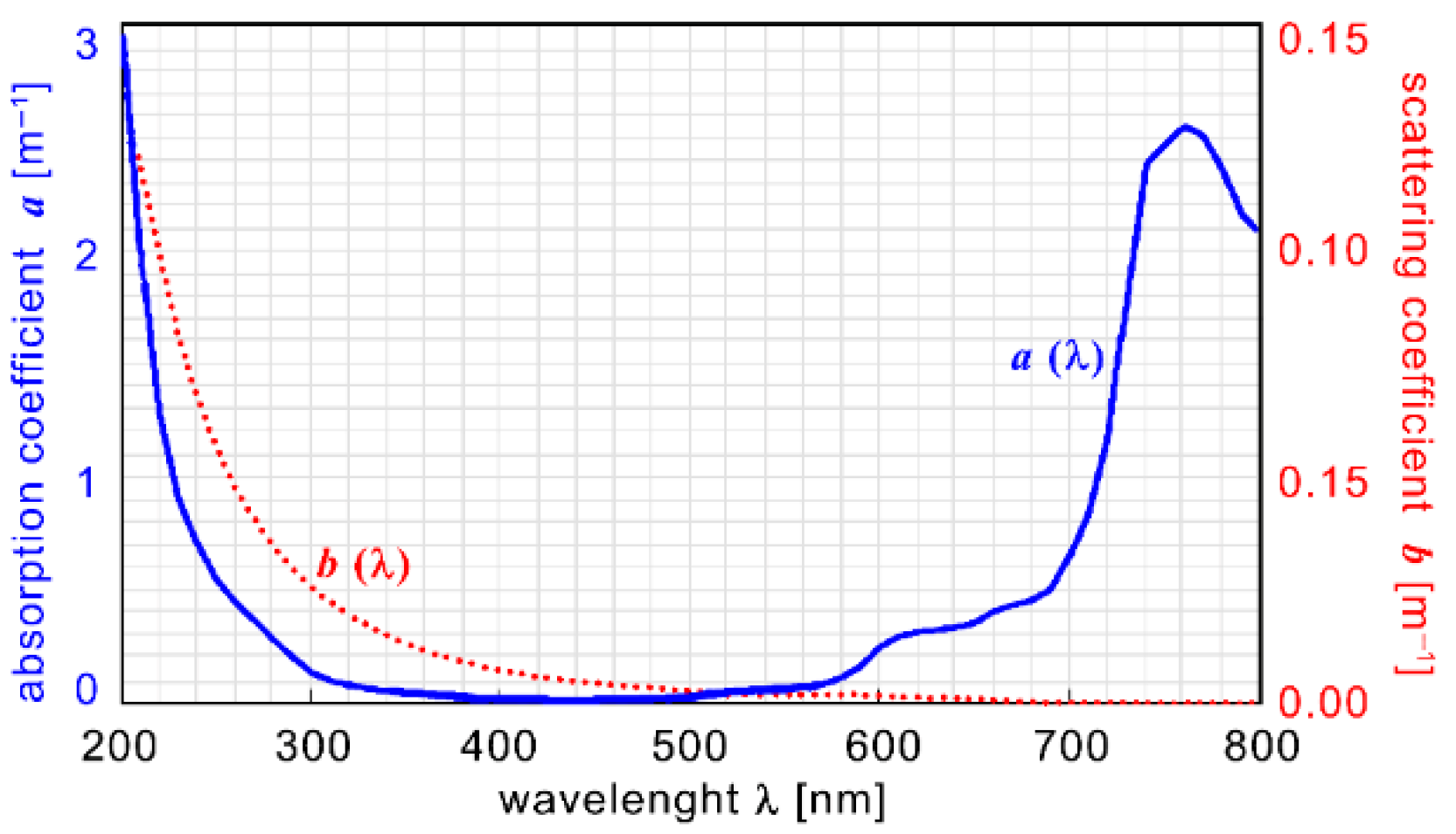
2. Absorption and Scattering
3. Underwater Optical Transmission in Turbid Water
4. Test System for Transmission UOWC Study
5. Experimental Tests
6. Future Directions
- (1)
- A narrow band optical filter centered on the wavelength of the light radiation to be “decoded”. This filter must have a pass band of, at most, 20 nm.
- (2)
- A lens to collect the light and collimate towards the sensor surface. This lens is used to intercept a light surface larger than the sensitive area of the detector.
- (3)
- Quadrant photodiode. The position of the divers will “hardly” remain fixed during transmission. Therefore, an “automatic” system will be needed to keep the line of sight between the two communicating divers “relatively” fixed. It is therefore planned to use a quadrant detector that allows to understand how to move the Tx–Rx station to maximize the received signal. The transmitter–receiver head can be adjusted using piezoelectric actuators to optimize alignment. This allows for proper alignment with minimal energy consumption. Since high-precision alignment is not required, the same photodiode can be used for both signal reception and alignment purposes [149,150,151].
- (4)
- If the alignment system is not sufficient to establish a reliable connection between the receiver and the transmitter, the diver may use a handheld flashlight-like transmitter/receiver. To initiate communication when no connection is present, the diver points the device directly at the intended recipient.
7. Discussion
8. Conclusions
Author Contributions
Funding
Institutional Review Board Statement
Informed Consent Statement
Data Availability Statement
Conflicts of Interest
References
- Poonia, A.; Pandey, S.; Vasundhara. Application of light emitting diodes (LEDs) for food preservation, post-harvest losses and production of bioactive compounds: A review. Food Prod. Process Nutr. 2022, 4, 10. [Google Scholar] [CrossRef]
- Mukunda, D.C.; Joshi, V.K.; Mahato, K.K. Light Emitting Diodes (LEDs) in Fluorescence-Based Analytical Applications: A Review. Appl. Spectrosc. Rev. 2020, 57, 1–38. [Google Scholar] [CrossRef]
- Paryavi, M.; Weiser, K.; Melzer, M.; Crook, D.; Ramadugu, C.; Jenkins, D.M. Programmable LED Array for Evaluating Artificial Light Sources to Improve Insect Trapping. Insects 2025, 16, 170. [Google Scholar] [CrossRef] [PubMed]
- Chen, J.; Loeba, S.; Kim, J.-H. LED revolution: Fundamentals and prospects for UV disinfection applications. Environ. Sci. Water Res. Technol. 2017, 3, 188–202. [Google Scholar] [CrossRef]
- Schirripa Spagnolo, G.; Cozzella, L.; Leccese, F.; Sangiovanni, S.; Podestà, L.; Piuzzi, E. Optical Wireless Communication and Li-Fi: A New Infrastructure for Wireless Communication in Saving Energy Era. In Proceedings of the 2020 IEEE International Workshop on Metrology for Industry 4.0 & IoT, Roma, Italy, 3–5 June 2020; pp. 674–678. [Google Scholar] [CrossRef]
- Yu, T.-C.; Huang, W.-T.; Lee, W.-B.; Chow, C.-W.; Chang, S.-W.; Kuo, H.-C. Visible Light Communication System Technology Review: Devices, Architectures, and Applications. Crystals 2021, 11, 1098. [Google Scholar] [CrossRef]
- Badeel, R.; Subramaniam, S.K.; Hanapi, Z.M.; Muhammed, A. A Review on LiFi Network Research: Open Issues, Applications and Future Directions. Appl. Sci. 2021, 11, 11118. [Google Scholar] [CrossRef]
- Ke, X. Principle and Research Progress of Visible Light Communication. In Handbook of Optical Wireless Communication; Springer: Singapore, 2024; pp. 1307–1345. [Google Scholar] [CrossRef]
- Loebner, E.E. Subhistories of the light emitting diode. IEEE Trans. Electron. Devices 1976, 23, 675–699. [Google Scholar] [CrossRef]
- Round, H.J. A Note on Carborundum. In Semicond. Devices Pioneer Papers; Sze, S.M., Ed.; World Scientific Publishing: Singapore, 1991; p. 879. [Google Scholar] [CrossRef]
- Schubert, E.F. History of light-emitting diodes. In Light-Emitting Diodes, 2nd ed.; Cambridge University Press: Cambridge, UK, 2006; pp. 1–26. [Google Scholar] [CrossRef]
- Losev, O.V. Luminous carborundum (silicon carbide) detector and detection with crystals. Telegr. I Telef. Bez. Provodov 1927, 19, 485–494. [Google Scholar]
- Ivey, H. Electroluminescence and semiconductor lasers. IEEE J. Quantum. Electron. 1966, 2, 713–726. [Google Scholar] [CrossRef]
- Zheludev, N. The life and times of the LED—A 100-year history. Nat. Photon. 2007, 1, 189–192. [Google Scholar] [CrossRef]
- Dupuis, R.D.; Krames, M.R. History, development, and applications of high-brightness visible light-emitting diodes. J. Light Technol. 2008, 26, 1154–1171. Available online: https://opg.optica.org/jlt/abstract.cfm?URI=jlt-26-9-1154 (accessed on 13 June 2025). [CrossRef]
- Pimputkar, S.; Speck, J.S.; DenBaars, S.P.; Nakamura, S. Prospects for LED lighting. Nat. Photon. 2009, 3, 180–182. [Google Scholar] [CrossRef]
- Canale, L. Discovery of LED Lighting: A History of Science between Research, Work and Serendipity. In Proceedings of the 4th International Conference on High Voltage Engineering and Power Systems (ICHVEPS), Denpasar Bali, Indonesia, 6–10 August 2023; pp. 856–861. Available online: https://10.1109/ICHVEPS58902.2023.10257422 (accessed on 13 June 2025).
- Esteki, M.; Khajehoddin, S.A.; Safaee, A.; Li, Y. LED Systems Applications and LED Driver Topologies: A Review. IEEE Access 2023, 11, 38324–38358. [Google Scholar] [CrossRef]
- Miyazaki, E.; Itami, S.; Araki, T. Using a light-emitting diode as a high-speed, wavelength selective photodetector. Rev. Sci. Instrum. 1998, 69, 3751–3754. [Google Scholar] [CrossRef]
- Kutzner, M.; Wright, R.; Kutzner, E. An inexpensive LED light sensor. Phys. Teach. 2010, 48, 341–343. [Google Scholar] [CrossRef]
- Schirripa Spagnolo, G.; Leccese, F.; Leccisi, M. LED as Transmitter and Receiver of Light: A Simple Tool to Demonstration Photoelectric Effect. Crystals 2019, 9, 531. [Google Scholar] [CrossRef]
- Chen, X.; Jin, M.; Lin, R.; Zhou, G.; Cui, X.; Tian, P. Visible light communication based on computational temporal ghost imaging and micro-LED-based detector. Opt. Lasers Eng. 2022, 152, 106956. [Google Scholar] [CrossRef]
- Nakamura, S. Nobel Lecture: Background story of the invention of efficient blue InGaN light emitting diodes. Rev. Mod. Phys. 2015, 87, 1139–1151. [Google Scholar] [CrossRef]
- Zeng, Z.; Fu, S.; Zhang, H.; Dong, Y.; Cheng, J. A survey of underwater optical wireless communications. IEEE Commun. Surv. Tutor. 2016, 19, 204–238. [Google Scholar] [CrossRef]
- Ali, M.F.; Jayakody, D.N.K.; Chursin, Y.A.; Affes, S.; Sonkin Dmitry, S. Advances and Future Directions on Underwater Wireless Communications. Arch. Comput. Methods Eng. 2020, 27, 1379–1412. [Google Scholar] [CrossRef]
- Zia, M.Y.I.; Poncela, J.; Otero, P. State-of-the-art underwater acoustic communication modems: Classifications, analyses and design challenges. Wirel. Pers. Commun. 2021, 116, 1325–1360. [Google Scholar] [CrossRef]
- Theocharidis, T.; Kavallieratou, E. Underwater communication technologies: A review. Telecommun. Syst. 2025, 88, 54. [Google Scholar] [CrossRef]
- Duntley, S.Q. Light in the sea. J. Opt. Soc. Am. 1963, 53, 214–233. [Google Scholar] [CrossRef]
- Callaham, M. Submarine communications. IEEE Commun. Mag. 1981, 19, 16–25. [Google Scholar] [CrossRef]
- Kaushal, H.; Kaddoum, G. Underwater optical wireless communication. IEEE Access 2016, 4, 518–1547. [Google Scholar] [CrossRef]
- Chen, C.; Zhang, X.; Rao, J. Optical design for an LED-based handheld underwater wireless optical communication system. Chin. Opt. Lett. 2015, 13, 020801. [Google Scholar] [CrossRef]
- Sun, K.; Li, Y.; Han, Z. Research on Underwater Wireless Optical Communication Channel Model and Its Application. Appl. Sci. 2024, 14, 206. [Google Scholar] [CrossRef]
- Wu, T.C.; Chi, Y.C.; Wang, H.Y.; Cheng-Ting Tsai, C.-T.; Gong-Ru Lin, G.-R. Blue Laser Diode Enables Underwater Communication at 12.4Gbps. Sci. Rep. 2017, 7, 40480. [Google Scholar] [CrossRef]
- Johnson, L.J.; Jasman, F.; Green, R.J.; Leeson, M.S. Recent advances in underwater optical wireless communications. Underw. Technol. 2014, 32, 167–175. [Google Scholar] [CrossRef]
- Tsai, W.-S.; Lu, H.-H.; Wu, H.-W.; Su, C.-W.; Huang, Y.-C. A 30 Gb/s PAM4 underwater wireless laser transmission system with optical beam reducer/expander. Sci. Rep. 2019, 9, 8605. [Google Scholar] [CrossRef] [PubMed]
- Shen, J.; Wang, J.; Yu, C.; Chen, X.; Wu, J.; Zhao, M.; Qu, F.; Xu, Z.; Han, J.; Xu, J. Single LED-based 46-m underwater wireless optical communication enabled by a multi-pixel photon counter with digital output. Opt. Commun. 2019, 438, 78–82. [Google Scholar] [CrossRef]
- Schirripa Spagnolo, G.; Cozzella, L.; Leccese, F. Underwater Optical Wireless Communications: Overview. Sensors 2020, 20, 2261. [Google Scholar] [CrossRef] [PubMed]
- Schirripa Spagnolo, G.; Cozzella, L.; Leccese, F. A Brief Survey on Underwater Optical Wireless Communications. In Proceedings of the MetroSea 2020-TC19 International Workshop on Metrology for the Sea, Naples, Italy, 5–7 October 2020; pp. 79–84. Available online: https://www.imeko.org/publications/tc19-Metrosea-2020/ (accessed on 15 May 2025).
- Wei, W.; Zhang, C.; Zhang, W.; Jiang, W.; Shu, C.; Xiaorui, Q. LED-Based Underwater Wireless Optical Communication for Small Mobile Platforms: Experimental Channel Study in Highly-Turbid Lake Water. IEEE Access 2020, 8, 169304–169313. [Google Scholar] [CrossRef]
- Sun, X.; Kang, C.H.; Kong, M.; Alkhazragi, O.; Guo, Y.; Ouhssain, M.; Weng, Y.; Jones, B.H.; Ng, T.K.; Ooi, B.O. A Review on Practical Considerations and Solutions in Underwater Wireless Optical Communication. J. Light Technol. 2020, 38, 421–431. [Google Scholar] [CrossRef]
- Rehman, S.; Rong, Y.; Chen, P. Designing an Adaptive Underwater Visible Light Communication System. Sensors 2025, 25, 1801. [Google Scholar] [CrossRef] [PubMed]
- Leccese, F.; Schirripa Spagnolo, G. State-of-the art and perspectives of underwater optical wireless communications. Acta IMEKO 2021, 10, 25–35. [Google Scholar] [CrossRef]
- Fang, C.; Li, S.; Wang, Y.; Wang, K. High-Speed Underwater Optical Wireless Communication with Advanced Signal Processing Methods Survey. Photonics 2023, 10, 811. [Google Scholar] [CrossRef]
- Shen, T.; Guo, J.; Liang, H.; Li, Y.; Li, K.; Dai, Y.; Ai, Y. Research on a Blue–Green LED Communication System Based on an Underwater Mobile Robot. Photonics 2023, 10, 1238. [Google Scholar] [CrossRef]
- Zhang, M.; Zhou, H. Real-Time Underwater Wireless Optical Communication System Based on LEDs and Estimation of Maximum Communication Distance. Sensors 2023, 23, 7649. [Google Scholar] [CrossRef] [PubMed]
- Vijayalakshmi, B.A.; Lekashri, S.; Gomathi, M.; Ashwini, A.; Arunsundar, B.; Nesasudha, M. VLC system using LEDs for transmitting underwater information. J. Opt. 2024, 2, 1–10. [Google Scholar] [CrossRef]
- Yuan, R.; Zhang, T.; Li, C.; Gao, H.; Hu, L. Laser Transmission Characteristics of Seawater for Underwater Wireless Optical Communication. Sensors 2025, 25, 3057. [Google Scholar] [CrossRef] [PubMed]
- Mobley, C.D. The Oceanic Optics Book; International Ocean Colour Co ordinating Group (IOCCG): Dartmouth, NS, Canada, 2022; p. 924. [Google Scholar] [CrossRef]
- Jerlov, N.G. Optical Oceanography; Elsevier: Amsterdam, The Netherlands, 1968; Volume 5. [Google Scholar] [CrossRef]
- Prieur, L.; Sathyendranath, S. An optical classification of coastal and oceanic waters based on the specific spectral absorption curves of phytoplankton pigments, dissolved organic matter, and other particulate materials 1. Limnol. Oceanogr. 1981, 26, 671–689. [Google Scholar] [CrossRef]
- Solonenko, M.G.; Mobley, C.D. Inherent optical properties of Jerlov water types. Appl. Opt. 2015, 54, 5392–5401. [Google Scholar] [CrossRef] [PubMed]
- Kumar, S.; Prince, S.; Aravind, J.A.; Kumar, G.S. Analysis on the effect of salinity in underwater wireless optical communication. Mar. Georesources Geotechnol. 2019, 38, 291–301. [Google Scholar] [CrossRef]
- Stramski, D.; Boss, E.; Bogucki, D.; Voss, K.J. The role of seawater constituents in light backscattering in the ocean. Prog. Oceanogr. 2004, 61, 27–56. [Google Scholar] [CrossRef]
- Williamson, C.A.; Hollins, R.C. Measured IOPs of Jerlov water types. Appl. Opt. 2022, 61, 9951–9961. [Google Scholar] [CrossRef] [PubMed]
- Williams, J. Optical properties of the ocean. Rep. Prog. Phys. 1973, 36, 1567. [Google Scholar] [CrossRef]
- Morel, A.; Loisel, H. Apparent optical properties of oceanic water: Dependence on the molecular scattering contribution. Appl. Opt. 1998, 37, 4765–4776. [Google Scholar] [CrossRef] [PubMed]
- Li, D.-C.; Chen, C.-C.; Liaw, S.-K.; Afifah, S.; Sung, J.-Y.; Yeh, C.-H. Performance Evaluation of Underwater Wireless Optical Communication System by Varying the Environmental Parameters. Photonics 2021, 8, 74. [Google Scholar] [CrossRef]
- Chlorophyll in Europe’s Transitional, Coastal and Marine Waters. Available online: https://www.eea.europa.eu/en/analysis/indicators/chlorophyll-in-transitional-coastal-and (accessed on 15 May 2025).
- Lodovisi, C.; Gerardi, F.; Aurizzi, M.M.; Betti, S. Underwater Optical Communication in Turbid Waters for Different Wavelengths: Performance Evaluation. In Proceedings of the 2024 Italian Conference on Optics and Photonics (ICOP), Firenze, Italy, 23 February–15 March 2024; pp. 1–4. [Google Scholar] [CrossRef]
- Raj, A.A.B.; Krishnan, P.; Darusalam, U.; Kaddoum, G.; Ghassemlooy, Z.; Abadi, M.M.; Majumdar, A.K.; Ijaz, M. A Review–Unguided Optical Communications: Developments, Technology Evolution, and Challenges. Electronics 2023, 12, 1922. [Google Scholar] [CrossRef]
- Vali, Z.; Michelson, D.; Ghassemlooy, Z.; Noori, H. A survey of turbulence in underwater optical wireless communications. Optik 2025, 320, 172126. [Google Scholar] [CrossRef]
- Li, S.; Zhang, Z.; Zhang, Q.; Yao, H.; Li, X.; Mi, J.; Wang, H. Breakthrough Underwater Physical Environment Limitations on Optical Information Representations: An Overview and Suggestions. J. Mar. Sci. Eng. 2024, 12, 1055. [Google Scholar] [CrossRef]
- Xu, J.; Song, Y.; Yu, X.; Lin, A.; Kong, M.; Han, J.; Deng, N. Underwater wireless transmission of high-speed QAM-OFDM signals using a compact red-light laser. Opt. Express 2016, 24, 8097–8109. [Google Scholar] [CrossRef] [PubMed]
- Hoeher, P.A.; Sticklus, J.; Harlakin, A. Underwater Optical Wireless Communications in Swarm Robotics: A Tutorial. IEEE Commun. Surv. Tutor. 2021, 23, 2630–2659. [Google Scholar] [CrossRef]
- Rayleigh, L.X. On the electromagnetic theory of light. Lond. Edinb. Dublin Philos. Mag. J. Sci. 1881, 12, 81–101. [Google Scholar] [CrossRef]
- Rayleigh, L. XXXIV. On the transmission of light through an atmosphere containing small particles in suspension, and on the origin of the blue of the sky. Lond. Edinb. Dublin Philos. Mag. J. Sci. 1899, 47, 375–384. [Google Scholar] [CrossRef]
- Khalighi, M.-A.; Hamza, T.; Bourennane, S.; Léon, P.; Opderbecke, J. Underwater wireless optical communications using silicon photo-multipliers. IEEE Photonics J. 2017, 9, 1–10. [Google Scholar] [CrossRef]
- Smith, R.C.; Baker, K.S. Optical properties of the clearest natural waters (200–800 nm). Appl. Opt. 1981, 20, 177–184. [Google Scholar] [CrossRef] [PubMed]
- Mobley, C.D.; Gentili, B.; Gordon, H.R.; Jin, Z.; Kattawar, G.W.; Morel, A.; Reinersman, P.; Stamnes, K.; Stavn, R.H. Comparison of numerical models for computing underwater light fields. Appl. Opt. 1993, 32, 7484–7504. [Google Scholar] [CrossRef] [PubMed]
- Garcia, R.; Gracias, N.; Nicosevici, T.; Prados, R.; Hurtos, N.; Campos, R.; Escartin, J.; Elibol, A.; Hegedus, R.; Neumann, L. Exploring the seafloor with underwater robots. In Computer Vision in Vehicle Technology: Land, Sea & Air; López, A.M., Imiya, A., Pajdla, T., Álvarez, J.M., Eds.; John Wiley & Sons Ltd: Hoboken, NJ, USA, 2017; pp. 75–99. [Google Scholar] [CrossRef]
- Yacobi, Y.Z. From Tswett to identified flying objects: A concise history of chlorophyll a use for quantification of phytoplankton. Isr. J. Plant Sci. 2012, 60, 243–251. [Google Scholar] [CrossRef]
- Bricaud, A.; Babin, M.; Morel, A.; Claustre, H. Variability in the chlorophyll-specific absorption coefficients of natural phytoplankton: Analysis and parameterization. J. Geophys. Res. Ocean 1995, 100, 13321–13332. [Google Scholar] [CrossRef]
- Haltrin, V.I. Chlorophyll-based model of seawater optical properties. Appl. Opt. 1999, 38, 6826–6832. [Google Scholar] [CrossRef] [PubMed]
- Perrine, Z.; Negi, S.; Sayre, R.T. Optimization of photosynthetic light energy utilization by microalgae. Algal Res. 2012, 1, 134–142. [Google Scholar] [CrossRef]
- Chlorophyll Fluorescence. Available online: https://www.oceanopticsbook.info/view/scattering/level-2/chlorophyll-fluorescence (accessed on 15 May 2025).
- Lahet, F.; Ouillon, S.; Forget, P. A three-component model of ocean color and its application in the Ebro River mouth area. Remote Sens. Environ. 2000, 72, 181–190. [Google Scholar] [CrossRef]
- Huang, X.; Yang, F.; Song, J. Hybrid LD and LED-based underwater optical communication: State-of-the-art, opportunities, challenges, and trends. Chin. Opt. Lett. 2019, 17, 100002. [Google Scholar] [CrossRef]
- Stavn, R.H. Lambert-Beer law in ocean waters: Optical properties of water and of dissolved/suspended material, optical energy budgets. Appl. Opt. 1988, 27, 222–231. [Google Scholar] [CrossRef] [PubMed]
- Gordon, H.R. Can the Lambert-Beer law be applied to the diffuse attenuation coefficient of ocean water? Limnol. Oceanogr. 1989, 34, 1389–1409. [Google Scholar] [CrossRef]
- Govinda Waduge, T.G.; Seet, B.-C.; Vopel, K. Geometric Implications of Photodiode Arrays on Received Power Distribution in Mobile Underwater Optical Wireless Communication. Sensors 2024, 24, 3490. [Google Scholar] [CrossRef] [PubMed]
- Rashed, A.N.Z.; Sharshar, H.A. Performance evaluation of short range underwater optical wireless communications for different ocean water types. Wirel. Pers. Commun. 2013, 72, 693–708. [Google Scholar] [CrossRef]
- Malathy, S.; Singh, M.; Malhotra, J.; Vasudevan, B.; Dhasarathan, V. Modeling and performance investigation of 4 × 20 Gbps underwater optical wireless communication link incorporating space division multiplexing of Hermite Gaussian modes. Opt. Quant. Electro. 2020, 52, 256. [Google Scholar] [CrossRef]
- Elfikky, A.; Boghdady, A.I.; Mumtaz, S.; Elsayed, E.E.; Singh, M.; Abd El-Mottaleb, S.A.; Mohsan, S.A.H.; Aly, M.H. Underwater visible light communication: Recent advancements and channel modeling. Opt. Quant. Electron. 2024, 56, 1617. [Google Scholar] [CrossRef]
- Vavoulas, A.; Sandalidis, H.G.; Varoutas, D. Underwater Optical Wireless Networks: A k-Connectivity Analysis. IEEE J. Ocean Eng. 2014, 39, 801–809. [Google Scholar] [CrossRef]
- Ali, M.F.; Jayakody, D.N.K.; Li, Y. Recent Trends in Underwater Visible Light Communication (UVLC) Systems. IEEE Access 2022, 10, 22169–22225. [Google Scholar] [CrossRef]
- Morel, A.; Prieur, L. Analysis of variations in ocean color 1. Limnol. Oceanogr. 1977, 22, 709–722. [Google Scholar] [CrossRef]
- Jerlov, N.G. Optical studies of ocean water. Rept. Swed. Deep.-Sea Exped. 1951, 3, 1–59. [Google Scholar]
- Jerlov, N.G. Marine Optics; Elsevier: Amsterdam, The Netherlands, 1976; p. 276. [Google Scholar] [CrossRef]
- Moser, P.M. Spectral transmission of light through seawater. Nav. Air Dev. Cent. Warm.-Pacific-Sierra Res. Corp. 1992, 1–16. Available online: https://apps.dtic.mil/sti/tr/pdf/AD1012965.pdf (accessed on 3 June 2025).
- Fu, X.; Ding, X.; Liang, Z.; Wang, Y. Jointly adversarial networks for wavelength compensation and dehazing of underwater images. Multimed. Tools Appl. 2023, 82, 32941–32965. [Google Scholar] [CrossRef]
- LUMA™ X, Long-Range Wireless Optical Modem. LUMA, Hydromea, Renens, Switzerland. Available online: https://files.hydromea.com/luma/LUMA_X.pdf (accessed on 13 June 2025).
- LUMA™ X-Uv, Long-Range Wireless Optical Modem Working in the Uv Spectrum. LUMA, Hydromea, Renens, Switzerland. Available online: https://files.hydromea.com/luma/LUMA_X-UV.pdf (accessed on 13 June 2025).
- LUMA™ FLEX Compact Optical Wireless Modem, Designed for Seamless Integration into Subsea Infrastructure or Sensor Packages, Hydromea, Renens, Switzerland. Available online: https://files.hydromea.com/luma/LUMA_FLEX.pdf (accessed on 13 June 2025).
- LUMA 500ER Optical Modem Delivers Exceptional Performance And Energy Efficiency in a Compact Design. Available online: https://files.hydromea.com/luma/LUMA_500ER.pdf (accessed on 13 June 2025).
- BlueComm 200, Sonardyne, Hampshire, UK. Available online: https://www.sonardyne.com/wp-content/uploads/2021/07/Sonardyne_8361_BlueComm_200.pdf (accessed on 3 June 2025).
- BlueComm 200 UV, Sonardyne, Hampshire, UK. Available online: https://www.sonardyne.com/wp-content/uploads/2025/01/Sonardyne_8361_BlueComm_200_UV.pdf (accessed on 13 June 2025).
- AQUAmodem®Op2, Aquatec Group Ltd, Basingstoke, UK. Available online: https://www.aquatecgroup.com/wp-content/uploads/2024/05/Aquatec_AQUAmodem_Op2_Datasheet.pdf (accessed on 13 June 2025).
- Shen, X.; Wang, T.; Wang, Z.; Zhu, R.; Jiang, L.; Tong, C.; Song, Y.; Zhang, P. Pulsed Laser Based Underwater Wireless Optical Communication: Smaller Channel Attenuation and Better Communication Performance. IEEE J. Ocean. Eng. 2025, 50, 1557. [Google Scholar] [CrossRef]
- Hu, S.; Mi, L.; Zhou, T.; Chen, W. 35.88 attenuation lengths and 3.32 bits/photon underwater optical wireless communication based on photon-counting receiver with 256-PPM. Opt. Express 2018, 26, 21685–21699. [Google Scholar] [CrossRef] [PubMed]
- Wang, J.; Lu, C.; Li, S.; Xu, Z. 100 m/500 Mbps underwater optical wireless communication using an NRZ-OOK modulated 520 nm laser diode. Opt. Express 2019, 27, 12171–12181. [Google Scholar] [CrossRef] [PubMed]
- Zhao, M.; Li, X.; Chen, X.; Tong, Z.; Lyu, W.; Zhang, Z.; Xu, J. Long-reach underwater wireless optical communication with relaxed link alignment enabled by optical combination and arrayed sensitive receivers. Opt. Express 2020, 28, 34450–34460. [Google Scholar] [CrossRef] [PubMed]
- Dai, Y.; Chen, X.; Yang, X.; Tong, Z.; Du, Z.; Lyu, W.; Zhang, C.; Zhang, H.; Zou, H.; Cheng, Y.; et al. 200-m/500-Mbps underwater wireless optical communication system utilizing a sparse nonlinear equalizer with a variable step size generalized orthogonal matching pursuit. Opt. Express 2021, 29, 32228–32243. [Google Scholar] [CrossRef] [PubMed]
- Chen, X.; Yang, X.; Tong, Z.; Dai, Y.; Li, X.; Zhao, M.; Zhang, Z.; Zhao, J.; Xu, J. 150 m/500 Mbps underwater wireless optical communication enabled by sensitive detection and the combination of receiver-side partial response shaping and TCM technology. J. Light. Technol. 2021, 39, 4614–4621. [Google Scholar] [CrossRef]
- Yang, X.; Tong, Z.; Dai, Y.; Chen, X.; Zhang, H.; Zou, H.; Xu, J. 100 m full-duplex underwater wireless optical communication based on blue and green lasers and high sensitivity detectors. Opt. Commun. 2021, 498, 127261. [Google Scholar] [CrossRef]
- Zhang, C.; Yang, X.; Zou, H.; Zhang, H.; Zhang, Y.; Dai, Y.; Song, G.; Zhang, Z.; Bo Wu, B.; Xu, J. 9.14-Mbps 64-PPM UWOC system based on a directly modulated MOPA with pre-pulse shaping and a high-sensitivity PMT with analog demodulation. Opt. Express 2022, 30, 30233–30245. [Google Scholar] [CrossRef] [PubMed]
- Ishibashi, S.; Susuki, K.-I. 1Gbps x 100m Underwater Optical Wireless Communication Using Laser Module in Deep Sea. In Proceedings of the OCEANS 2022, Hampton Roads, VA, USA, 19 December 2022; pp. 1–7. [Google Scholar] [CrossRef]
- Ge, W.; Du, Z.; Cai, C.; Song, G.; Qin, S.; Wang, H.; Zhang, T.; Xu, J. 90-m/560-Mbps underwater wireless optical communication utilizing subband multiple-mode full permutation CAP combined with an SNR-weighted detector and multi-channel DFE. Opt. Express 2023, 31, 13154–13168. [Google Scholar] [CrossRef] [PubMed]
- Hameed, S.M.; Sabri, A.A.; Abdulsatar, S.M. Filtered OFDM for underwater wireless optical communication. Opt. Quantum Electron. 2023, 55, 77. [Google Scholar] [CrossRef]
- Ghazy, A.S.; Hranilovic, S.; Khalighi, M.-A. Angular MIMO for Underwater Wireless Optical Communications: Link Modeling and Tracking. IEEE J. Ocean. Eng. 2021, 46, 1391–1407. [Google Scholar] [CrossRef]
- Chen, D.; Li, Z.; Wang, J.; Lu, H.; Hao, R.; Fan, K.; Jin, J.; Wang, Q.; Wu, S. Experimental study of laser spot tracking for underwater optical wireless communication. Opt. Express 2024, 32, 6409–6422. [Google Scholar] [CrossRef] [PubMed]
- Wang, J.; Liu, W.; Huang, N.; Xu, Z.; Chen, Y. Design and Implementation of Automatic Beam Alignment System for LD-PMT Based UOWC. In Proceedings of the 2025 IEEE Wireless Communications and Networking Conference (WCNC), Milano, Italy, 9 May 2025; pp. 1–7. [Google Scholar] [CrossRef]
- Huber, E.; Frost, M. Light scattering by small particles. J. Water Supply: Res. Technol.—AQUA 1998, 47, 87–94. [Google Scholar] [CrossRef]
- Jonasz, M.; Fournier, G. Light Scattering by Particles in Water: Theoretical and Experimental Foundations; Academic Press: New York, NY, USA, 2007. [Google Scholar] [CrossRef]
- Zhang, X.; Hu, L. Light scattering by pure water and seawater: Recent development. J. Remote Sens. 2021, 2021, 9753625. [Google Scholar] [CrossRef]
- Sawa, T. Research and development for practical use of underwater optical wireless communication. In Proceedings of the 2023 IEEE Underwater Technology (UT), Tokyo, Japan, 24 April 2023; pp. 1–5. [Google Scholar] [CrossRef]
- Majlesein, B.; Gholami, A.; Ghassemlooy, Z. Investigation of the Scattering Noise in Underwater Optical Wireless Communications. Sci. 2021, 3, 27. [Google Scholar] [CrossRef]
- Li, S.S. Light-Emitting Devices. Semiconductor Physical Electronics; Springer: New York, NY, USA, 2006; pp. 458–512. [Google Scholar] [CrossRef]
- Zhu, D.; Humphreys, C.J. Solid-State Lighting Based on Light Emitting Diode Technology. In Optics in Our Time; Al-Amri, M., El-Gomati, M., Zubairy, M., Eds.; Springer: Cham, Switzerland, 2016; pp. 87–118. [Google Scholar] [CrossRef]
- Krames, M.R.; Shchekin, O.B.; Mueller-Mach, R.; Mueller, G.O.; Zhou, L.; Harbers, G.; Craford, M.G. Status and Future of High-Power Light-Emitting Diodes for Solid-State Lighting. J. Disp. Technol. 2007, 3, 160–175. [Google Scholar] [CrossRef]
- Pleasants, S. Overcoming the ‘green gap’. Nat. Photon. 2013, 7, 585. [Google Scholar] [CrossRef]
- Der Maur, M.A.; Pecchia, A.; Penazzi, G.; Rodrigues, W.; Di Carlo, A. Unraveling the “Green Gap” problem: The role of random alloy fluctuations in InGaN/GaN light emitting diodes. Phys. Rev. Lett. 2016, 116, 027401. [Google Scholar] [CrossRef] [PubMed]
- Rogers, D.J.; Teherani, F.H.; Bove, P.; McClintock, R.; Razeghi, M. Improved LEDs and photovoltaics by hybridization & and nanostructuring. SPIE Newsroom 2012, 10, 004238. [Google Scholar] [CrossRef]
- Schirripa Spagnolo, G.; Leccese, F. LED Rail Signals: Full Hardware Realization of Apparatus with Independent Intensity by Temperature Changes. Electronics 2021, 10, 1291. [Google Scholar] [CrossRef]
- Al-Zhrani, S.; Bedaiwi, N.M.; El-Ramli, I.F.; Barasheed, A.Z.; Abduldaiem, A.; Al-Hadeethi, Y.; Umar, A. Underwater optical communications: A brief overview and recent developments. Eng. Sci. 2021, 16, 146–186. [Google Scholar] [CrossRef]
- Donati, S. Photodetectors: Devices, Circuits and Applications; John Wiley & Sons. Inc.: Hoboken, NJ, USA, 2021. [Google Scholar] [CrossRef]
- Bielecki, Z.; Achtenberg, K.; Kopytko, M.; Mikołajczyk, J.; Wojtas, J.; Rogalski, A. Review of photodetectors characterization methods. Bull. Pol. Acad. Sciences. Tech. Sci. 2022, 70, 140534. [Google Scholar] [CrossRef]
- Georgel, R.; Grygoryev, K.; Sorensen, S.; Lu, H.; Andersson-Engels, S.; Burke, R.; O’Hare, D. Silicon Photomultiplier—A High Dynamic Range, High Sensitivity Sensor for Bio-Photonics Applications. Biosensors 2022, 12, 793. [Google Scholar] [CrossRef] [PubMed]
- PicoQuant Single Photon Avalanche Diodes. Available online: https://www.picoquant.com/products/category/photon-counting-detectors/pdm-series-single-photon-avalanche-diodes (accessed on 11 July 2025).
- Hamamatsu SPAD Modules. Available online: https://www.hamamatsu.com/eu/en/product/optical-sensors/mppc/photon-counting-module.html (accessed on 11 July 2025).
- Silicon Photomultipliers (SiPM), Low Noise, Blue-Sensitive. C-Series SiPM Sensors. Available online: https://www.onsemi.com/pdf/datasheet/microc-series-d.pdf (accessed on 11 July 2025).
- Hamamatsu MPPC (Multi-Pixel Photon Counter). Available online: https://www.hamamatsu.com/eu/en/product/optical-sensors/mppc.html (accessed on 11 July 2025).
- TE PIN Photodiode (Model PS13-6b TO). Available online: https://www.te.com/en/product-3001225-F.html (accessed on 11 July 2025).
- OSI Optoelectronics Photoconductive Photodiodes. Available online: https://www.osioptoelectronics.com/products/photodetectors/photoconductive (accessed on 11 July 2025).
- Excelitas Avalanche Photodiodes (APDs). Available online: https://www.excelitas.com/product-category/avalanche-photodiodes (accessed on 11 July 2025).
- Mouser Avalanche Photodiodes. Available online: https://www.mouser.it/c/sensors/optical-sensors/photodiodes/?product=Avalanche%20Photodiodes&srsltid=AfmBOopxjcnlbHYIDbneFj0VbjMdaFAJXETpJb6rBXEw1aJQBRu2ULl8 (accessed on 11 July 2025).
- Hamamatsu Photomultiplier Tubes (PMTs). Available online: https://www.hamamatsu.com/eu/en/product/optical-sensors.html (accessed on 11 July 2025).
- Thorlabs Photomultiplier Modules (PMTs). Available online: https://www.thorlabs.com/newgrouppage9.cfm?objectgroup_id=2909 (accessed on 11 July 2025).
- Mahdi, H.A.; Abd, H.J.; Mansoor, R.; Janabi, A.H. Effective signal modulation for robust underwater optical wireless networks. J. Opt. 2025, 54, 13–23. [Google Scholar] [CrossRef]
- Junejo, N.U.R.; Sattar, M.; Adnan, S.; Sun, H.; Adam, A.B.M.; Hassan, A.; Esmaiel, H. A Survey on Physical Layer Techniques and Challenges in Underwater Communication Systems. J. Mar. Sci. Eng. 2023, 11, 885. [Google Scholar] [CrossRef]
- Abd El-Mottaleb, S.A.; Singh, M.; Atieh, A.; Aly, M.H. High data rate underwater optical wireless communication systems with ICSM codes within green spectrum. Opt. Quant. Electron. 2025, 57, 213. [Google Scholar] [CrossRef]
- Matarneh, A.M.; Rwaidi, A.M.; ALjA’afreh, S.S. Evaluating 60 GHz band Underwater Optical Wireless Communication Performance Based on Low-Density Parity Check Coding Under Diverse Water Conditions and Noise Levels. IEEE Access 2025, 13, 97129–97151. [Google Scholar] [CrossRef]
- Nedelsky, L. Introductory physics laboratory. Am. J. Phys. 1958, 26, 51–59. [Google Scholar] [CrossRef]
- Hofstein, A.; Lunetta, V.N. The role of the laboratory in science teaching: Neglected aspects of research. Rev. Educ. Res. 1982, 52, 201–217. [Google Scholar] [CrossRef]
- Schirripa Spagnolo, G.; Postiglione, A.; De Angelis, I. Simple equipment for teaching internal photoelectric effect. Phys. Educ. 2020, 55, 055011. [Google Scholar] [CrossRef]
- Flood, J.E. Digital modulation. In Telecommunications Engineer’s Reference Book; Mazda, F., Ed.; Butterworth Heinemann: Oxford, UK, 1993. [Google Scholar] [CrossRef]
- Hecht, E. Optics, 5th ed.; Pearson Education Ltd.: Harlow, UK, 2016. [Google Scholar]
- Mullen, L.; Alley, D.; Cochenour, B. Investigation of the effect of scattering agent and scattering albedo on modulated light propagation in water. Appl. Opt. 2011, 50, 1396–1404. [Google Scholar] [CrossRef] [PubMed]
- Arvanitakis, G.N.; Bian, R.; McKendry, J.J.; Cheng, C.; Xie, E.; He, X.; Yang, G.; Mohamed, S.; Islim, M.S.; Gu, E.; et al. Gb/s underwater wireless optical communications using series-connected GaN micro-LED arrays. IEEE Photonics J. 2019, 12, 7901210. [Google Scholar] [CrossRef]
- Saeed, N.; Celik, A.; Al-Naffouri, T.Y.; Alouini, M.S. Underwater optical wireless communications, networking, and localization: A survey. Ad. Hoc Netw. 2019, 94, 101935. [Google Scholar] [CrossRef]
- Han, B.; Zhao, W.; Zheng, Y.; Meng, J.; Wang, T.; Han, Y.; Wang, W.; Su, Y.; Duan, T.; Xie, X. Experimental demonstration of quasi-omni-directional transmitter for underwater wireless optical communication based on blue LED array and freeform lens. Opt. Commun. 2019, 434, 184–190. [Google Scholar] [CrossRef]
- Weng, Y.; Matsuda, T.; Sekimori, Y.; Pajarinen, J.; Peters, J.; Maki, T. Establishment of line-of-sight optical links between autonomous underwater vehicles: Field experiment and performance validation. Appl. Ocean Res. 2022, 129, 103385. [Google Scholar] [CrossRef]
- Li, X.; Tong, Z.; Lyu, W.; Chen, X.; Yang, X.; Zhang, Y.; Liu, S.; Dai, Y.; Zhang, Z.; Guo, C.; et al. Underwater quasi-omnidirectional wireless optical communication based on perovskite quantum dots. Opt. Express 2022, 30, 1709–1722. [Google Scholar] [CrossRef] [PubMed]
- Zhang, H.; Gao, Y.; Tong, Z.; Yang, X.; Zhang, Y.; Zhang, C.; Xu, J. Omnidirectional optical communication system designed for underwater swarm robotics. Opt. Express 2023, 31, 18630–18644. [Google Scholar] [CrossRef] [PubMed]


| Light Source | Advantages | Drawbacks |
|---|---|---|
| LASER | High directionality. Lasers produce a low-divergence beam. This allows for long-distance transmission with low dispersion. High data rate. Due to the coherent nature of the light emitted by lasers, systems using this type of light source can support high-speed data transmission. | Alignment sensitivity. The narrow beam of light, typical of lasers, requires precise alignment between the transmitter and receiver. This makes lasers difficult to use in dynamic underwater environments. Dispersion issues. Particles suspended in the water can cause dispersion, reducing signal quality. High cost. Laser systems tend to be more expensive than LED-based solutions. |
| LED | Wide Beam. LEDs emit a relatively wide beam of light. This reduces the need for precise alignment between the transmitter and receiver, making it easier to implement systems that can be used in dynamic underwater environments. Cost-effective. LED-based systems are generally cheaper to manufacture and maintain. Resistance to water turbulence. The wider beam is less affected by small movements or disturbances in the water. | Lower data rates. LEDs cannot be modulated at high frequencies. In addition, LEDs are poorly suited to complex modulation schemes. Data rates are generally in the Mbps range. Low communication distance. Due to the lower optical power density (divergent beam), the effective communication range is in the order of 10 m. |
| Component | Absorption Coefficient | Scattering Coefficient |
|---|---|---|
| Pure water | The absorption of UV, blue and green light is low. | In the range (400–700 nm) can be neglected. |
| Chlorophyll and humic and fulvic acids | Low value of absorption in the range 550–630 nm. | Can be neglected. |
| CDOM (Colored Dissolved Organic Matter) | Vary with the concentration of CDOM. The absorption of blue light is strong. | Can be neglected. |
| Plankton | Vary with the concentration of plankton. | Mie scattering. Vary with the concentration of plankton. Decrease monotonously with λ. |
| Detritus | Vary with the concentration of detritus. Decrease monotonously with λ. | Mie scattering. Vary with the concentration of detritus. Decrease monotonously with λ. |
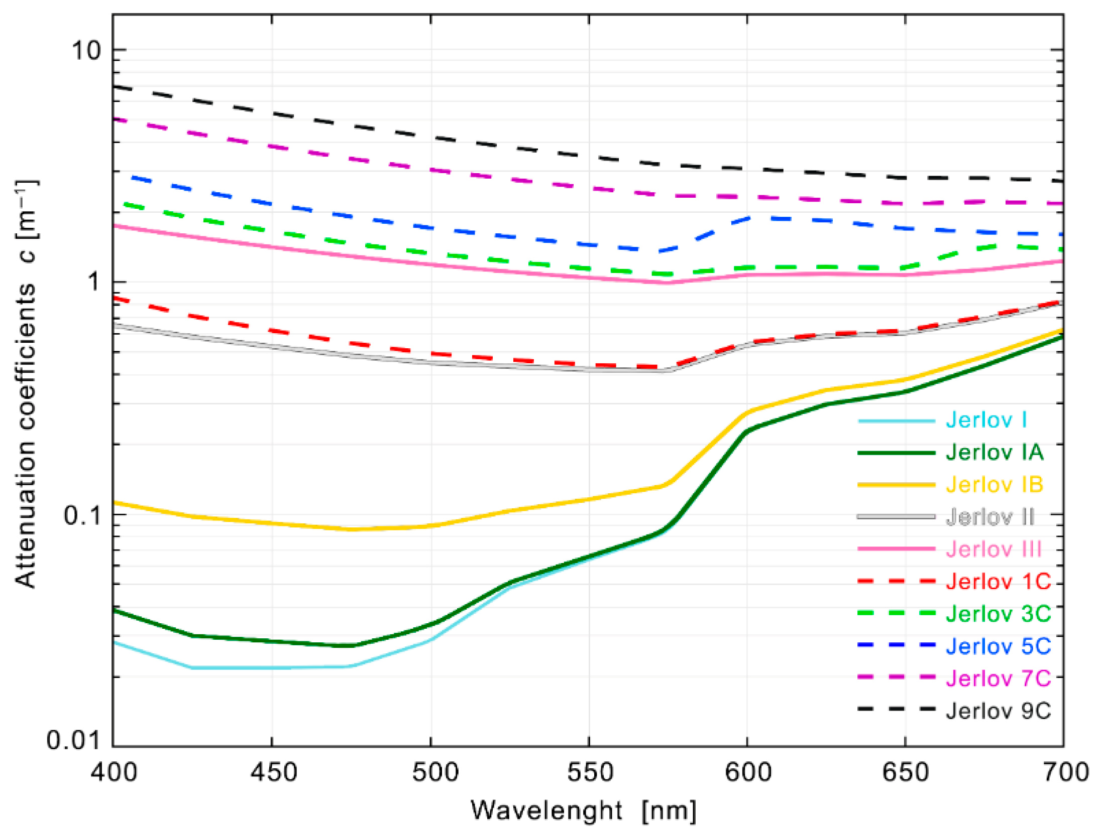
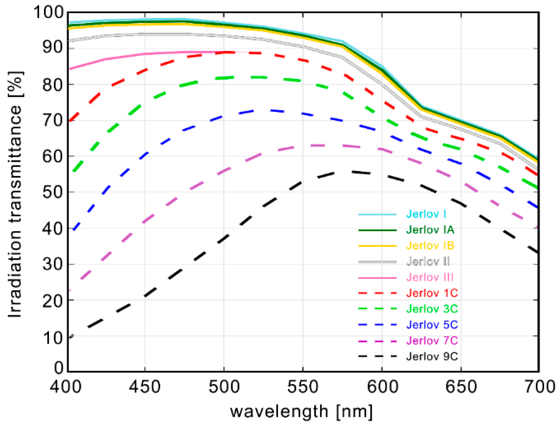
| Open ocean | Jerlov I Jerlov IA Jerlov IB Jerlov II Jerlov III | Very clear Very turbid |
| Coastal | Jerlov IA Jerlov 3C Jerlov 5C Jerlov 7C Jerlov 9C |
| Maker. | Model | Transmitter Type and Used Color | Data Rate (Max) | Operating Range |
|---|---|---|---|---|
| Hydromea Ref. [91] | LUMA™ X | LED 480 nm (blu) | 10 Mbps | max 50 m depending on turbidity |
| Hydromea Ref. [92] | LUMA™ X-UV | LED 395 nm (UV) | 10 Mbps | max 50 m depending on turbidity |
| Hydromea Ref. [93] | LUMA™ FLEX | LED 475 nm (blu) | 500 kbps | max 100 m Values based on calculations. The actual achievable range depends on water conditions such as turbidity and ambient light levels. |
| Hydromea Ref. [94] | LUMA™ 500ER | LED 475 nm (LED) | 500 kbps | greater than 50 m depending on turbidity |
| Sonardyne Ref. [95] | BlueComm 200 | LED 450 nm (blue) | 10 Mbps | max 150 m Optimal performance: Perfect for moderate-to-low turbidity dark water (>200 m depth or at night) |
| Sonardyne Ref. [96] | BlueComm 200 UV | LED 405 nm (UV) | 10 Mbps | max 75 m maintains reliable communication even with artificial lighting present |
| Aquamodem Ref. [97] | AQUAmodem® Op2 (Subsea Optical Modem) | LED Cyan | 115.200 | Typically 1–2 m |
| Year | Trasmitter | Optical Power | Detector | Distance | Reference |
|---|---|---|---|---|---|
| 2018 | Laser a stato solido (532 nm) | 1 mJ (pulsed energy) | SPD | 120 m | [99] |
| 2019 | Laser Diode (520 nm) | 7.25 mW | APD | 100 m | [100] |
| 2020 | 3× Laser Diode (450 nm) | 3 × 0.8 W | SiPM | 100 m | [101] |
| 2021 | Laser Diode (250 nm) | 288.4 mW | PMT | 200 m | [102] |
| 2021 | Laser Diode (450 nm) | 293.09 mW | PMT | 150 m | [103] |
| 2021 | Laser Diode (450 nm) Laser Diode (520 nm) | ~1.2 W ~1.0 W | 2× PMT | 139 m | [104] |
| 2022 | Fiber Laser (532 nm) | 600 mW | PMT | 99 m | [105] |
| 2022 | 5× Laser Diode (520 nm) | 5× 0.7 W (3.5 W) | 4× PMT | 100 m | [106] |
| 2023 | Laser Diode (450 nm) | ~1.2 W | PMT | 90 m | [107] |
| 2023 | Laser a stato solido (532 nm) | 1 W | APD | 80 m | [108] |
| Feature | SPAD [128,129] | SiPM [130,131] | PIN [132,133] | APD [134,135] | PMT [136,137] |
|---|---|---|---|---|---|
| Responsivity | Very High | Very High | Moderate | High | Very High |
| Bandwidth | Fast | Fast | Fast | Slow | Fast |
| Power Consumption | Medium | Medium | Very Low | Medium | High |
| Spectral Range (nm) | 400–1100 | 400–1100 | Variable * | ||
| Peak Sensitivity (nm) | 400–600 nm | 420 | 900 | 620 | Variable * |
| Dark noise | High | High | Low | Medium | Low |
| Operative Voltage | Medium | Medium | Low | Medium | High |
| Cost | Moderate–High | High | Low | Medium | High |
| Pure Water | Salt Water (35 g/L) | Salt Water (35 g/L) + Maalox (3 × 10⁻³%) | Salt Water (35 g/L) + Maalox (3 × 10⁻³%) + Chlorophyll (12 mg/m3) | |
|---|---|---|---|---|
| Light source made with 9 blue LEDs (~470 nm) | ||||
| Attenuation coefficient [m−1] | 0.011 | 0.016 | 1.8 | 4.8 |
| Propagation length [m] | ~25 | ~18 | ~1.1 | ~0.3 |
| Light source made with 12 Green LEDs (~520 nm) | ||||
| Attenuation coefficient [m−1] | 0.033 | 0.048 | 2.2 | 3.9 |
| Propagation length [m] | ~16 | ~13 | ~1.3 | ~0.5 |
| Light source made with 16 Amber LEDs (~610 nm) | ||||
| Attenuation coefficient [m−1] | 0.26 | 0.29 | 1.2 | 3.1 |
| Propagation length [m] | ~5 | ~4 | ~2.0 | ~1.0 |
| Light source made with 16 Red LEDs (~635 nm) | ||||
| Attenuation coefficient [m−1] | 0.30 | 0.33 | 1.2 | 2.8 |
| Propagation length [m] | ~5 | ~5 | ~2.0 | ~1.2 |
| Light source made with 9 blue LEDs (~470 nm) + Light source made with 8 Amber LEDs (~610 nm) | ||||
| Attenuation coefficient [m−1] | 0.011 | 0.016 | 1.1 | 3.1 |
| Propagation length [m] | ~25 | ~18 | ~2.0 | ~1.0 |
Disclaimer/Publisher’s Note: The statements, opinions and data contained in all publications are solely those of the individual author(s) and contributor(s) and not of MDPI and/or the editor(s). MDPI and/or the editor(s) disclaim responsibility for any injury to people or property resulting from any ideas, methods, instructions or products referred to in the content. |
© 2025 by the authors. Licensee MDPI, Basel, Switzerland. This article is an open access article distributed under the terms and conditions of the Creative Commons Attribution (CC BY) license (https://creativecommons.org/licenses/by/4.0/).
Share and Cite
Schirripa Spagnolo, G.; Satta, G.; Leccese, F. LEDs for Underwater Optical Wireless Communication. Photonics 2025, 12, 749. https://doi.org/10.3390/photonics12080749
Schirripa Spagnolo G, Satta G, Leccese F. LEDs for Underwater Optical Wireless Communication. Photonics. 2025; 12(8):749. https://doi.org/10.3390/photonics12080749
Chicago/Turabian StyleSchirripa Spagnolo, Giuseppe, Giorgia Satta, and Fabio Leccese. 2025. "LEDs for Underwater Optical Wireless Communication" Photonics 12, no. 8: 749. https://doi.org/10.3390/photonics12080749
APA StyleSchirripa Spagnolo, G., Satta, G., & Leccese, F. (2025). LEDs for Underwater Optical Wireless Communication. Photonics, 12(8), 749. https://doi.org/10.3390/photonics12080749