Article

Integrated Multiband-Mode Multiplexing Photonic Lantern for Selective Mode Excitation and Preservation

1
School of Electrical and Information Engineering, Yunnan Minzu University, Kunming 650500, China
2
Yunnan Key Laboratory of Unmanned Autonomous Systems, Kunming 650500, China
*
Author to whom correspondence should be addressed.
Photonics 2025, 12(7), 729; https://doi.org/10.3390/photonics12070729
Submission received: 26 June 2025 / Revised: 14 July 2025 / Accepted: 15 July 2025 / Published: 17 July 2025

Abstract

We propose and experimentally demonstrate an Integrated Multiband-Mode Multiplexing Photonic Lantern (IM3PL) that enables the selective excitation of high-order modes and stable modal preservation across multiple wavelength bands. As a proof-of-concept configuration, the IM3PL integrates a custom-designed input fiber array composed of three 980 nm single-mode fibers (SMFs) and two few-mode fibers (FMFs) operating at 1310 nm and 1550 nm, respectively. Simulations verify that 980 nm input signals can selectively excite L P 01 , L P 11 a , and L P 11 b modes at the FMF output, while the modal integrity of high-order linear polarized modes is preserved at 1310 nm and 1550 nm. The fabricated IM3PL device is experimentally validated via near-field pattern measurements, confirming the selective excitation at 980 nm and low-loss, mode-preserving transmission at the signal bands. This work offers a scalable and reconfigurable solution for multiband high-order-mode multiplexing, with promising applications in mode-division multiplexed fiber communication systems and multiband high-mode fiber lasers.

1. Introduction

The continuous growth in data transmission demand and the pursuit of higher functional integration in fiber photonic systems have stimulated significant research into mode-division multiplexing (MDM) using few-mode fibers (FMFs) [1,2,3]. By allowing multiple orthogonal spatial modes to propagate in parallel within a single fiber core, FMFs provide a scalable solution to overcome the capacity bottlenecks of single-mode fiber systems [4]. In addition to communications, spatial mode manipulation in FMFs has been leveraged for mode-selective fiber lasers, enabling flexible beam shaping, wavelength tuning, and high-order modal lasing [5,6,7].
Within this context, photonic lanterns have emerged as compact, low-loss, and integrable mode multiplexers that seamlessly connect multiple single-mode inputs with a multimode or few-mode waveguide [8,9,10]. Originally developed for astronomical spectroscopy and telescope coupling [11,12], photonic lanterns have evolved into versatile components for applications such as spatial multiplexing [13], mode-switchable fiber lasers [14], cylindrical vector beam generation [15], and fiber-integrated modal sensing [16]. Their compatibility with fiber-based manufacturing, such as fused-taper transitions, microstructured preforms, and femtosecond laser inscription, makes them especially attractive for all-fiber communication and laser architectures [17,18,19].
Despite these advantages, most photonic lanterns reported to date operate within a single wavelength band, typically the C-band (~1550 nm), and are optimized either for mode-selective excitation [20] or mode-preserving transmission [21]. Multiband multi-mode integration within a single photonic lantern structure has only recently begun to attract attention [22], but remains a largely underexplored area. Achieving efficient modal multiplexing across widely separated spectral channels introduces challenges such as mode-dependent phase mismatch, inter-band crosstalk, and the need for a wavelength-agnostic adiabatic taper design [23,24].
In our previous work [25], we reported a self-matching photonic lantern that selectively excited high-order modes at 980 nm while preserving modal profiles at 1550 nm, demonstrating its application in all-FMF ring-laser cavities. However, that work was limited to a two-wavelength configuration and did not explore the feasibility of extending the photonic lantern to support multiple wavelengths and modal channels simultaneously. This leaves open a fundamental question: Can a single photonic lantern be engineered to accommodate multiband multi-mode excitation and transmission in a unified, compact device?
To address this, this work proposes and experimentally demonstrates an Integrated Multiband-Mode Multiplexing Photonic Lantern (IM3PL) that achieves high-order-mode excitation at designated wavelengths while ensuring mode preservation across several transmission bands. To validate the concept, the IM3PL is demonstrated using 980 nm for high-order-mode excitation and 1310 nm and 1550 nm for low-loss, mode-preserving transmission. Beyond the demonstrated wavelengths, the device design is versatile and readily adaptable to various multiband configurations as required by different applications. The multiband design offers a compact and scalable solution for mode-division multiplexing systems and high-order-mode fiber lasers, paving the way for integrated, multi-wavelength photonic platforms.

2. Design of an Integrated Multiband-Mode Multiplexing Photonic Lantern (IM3PL)

To enable the excitation and stable transmission of high-order modes across multiple wavelength bands, the Integrated Multiband-Mode Multiplexing Photonic Lantern (IM3PL) is proposed. The IM3PL supports wavelength-selective excitation as well as mode-preserving transmission across multiple spectral bands. In this work, we present a proof-of-concept device configured for multiplexing at 980 nm, 1310 nm, and 1550 nm—wavelengths commonly used in fiber laser systems for pumping and signal delivery. This prototype is intended to demonstrate the feasibility of the device, which can be readily extended to other wavelength combinations in future designs.
As illustrated in Figure 1, the IM3PL structure consists of three main sections: an input fiber array, a tapered transition region, and a few-mode output port. The input array includes three single-mode fibers (SMFs) for 980 nm, one FMF for 1310 nm, and one FMF for 1550 nm. The output end is designed as a single FMF port whose parameters match those of the 1310 nm and 1550 nm fibers. A gradually varying tapered structure connects the input and output regions, ensuring continuous optical field transition via an adiabatic tapering process. The tapered region is designed to reduce insertion loss and mode interference, enhancing overall multiplexing performance.
The IM3PL integrates high-order-mode-selective excitation at 980 nm with mode-preserving transmission capabilities at 1310 nm and 1550 nm. The core design concept involves incorporating few-mode fibers (FMFs) capable of supporting a multiband operation in the input fiber array. These FMFs are carefully selected based on precise structural parameter calculations, and the overall device geometry is engineered through an adiabatic tapering process. This enables efficient mode transformation and preservation across different bands within a single IM3PL device, achieving multiband-mode excitation and multiplexing functionality.

3. Simulation and Analysis of the IM3PL

To demonstrate the feasibility of the proposed concept, we carried out simulations on a representative IM3PL configured to operate at 980 nm, 1310 nm, and 1550 nm. A comprehensive structural model of the photonic lantern was established, and finite element method (FEM) simulations were performed to analyze light propagation and modal evolution within the taper region. Particular attention was paid to the mode-selective excitation performance at 980 nm and the mode-preserving capabilities at 1310 nm and 1550 nm. The simulations took into account variations in fiber dimensions, numerical aperture, and taper ratios, as well as their effects on the effective refractive index and mode field distributions. These factors were carefully evaluated to ensure that the device would perform reliably under practical design parameters.

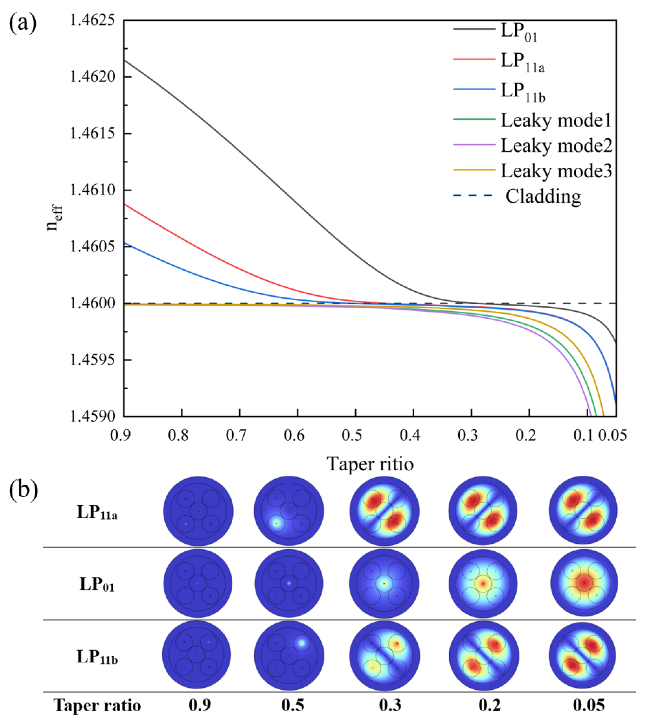
3.1. Mode-Selective Excitation at 980 nm

Following the principles of a mode-selective lantern design, the input array was configured with three 980 nm SMFs, each optimized for coupling to a specific mode. To ensure practical relevance of the simulation results, the structural model and fiber parameters were chosen to approximate real-world fabrication conditions. The numerical aperture of the 980 nm SMFs was approximately 0.12, with core and cladding refractive indices set to 1.4649 and 1.4600, respectively. The three SMFs featured different core diameters: one fiber with a larger 6 μm core was designed to excite the L P 01 mode, while the other two fibers had smaller core diameters of 3.5 μm and 4.5 μm to selectively excite the L P 11 a and L P 11 b modes, respectively.
As shown in Figure 2, the simulation results illustrate the mode-selective excitation of 980 nm light in the IM3PL. When light from the three 980 nm single-mode fibers—each with a different core size—enters the tapered region of the photonic lantern, the effective refractive indices of the guided modes gradually decrease as the taper ratio is reduced. Larger core diameters correspond to higher effective indices. This design takes advantage of the differing coupling sensitivities of individual waveguides to specific high-order modes, thereby enabling selective excitation. Moreover, during taper transition, the effective indices of the modes remain sufficiently separated (Figure 2a), which helps suppress intermodal crosstalk and ensures ordered mode output at the few-mode port.
As the taper ratio decreases, the optical field gradually leaks from the original fiber core into the cladding. This is due to the progressive reduction and eventual disappearance of the core, which causes the original cladding to serve as the new guiding region, while the outer jacket functions as the new cladding—thus forming a restructured waveguide. Further analysis of the mode field evolution (Figure 2b) revealed that, with a decreasing taper ratio, the modes gradually reconfigure and redistribute within the few-mode output port formed by the taper. When the taper ratio reaches 0.05, all three target modes establish stable field distributions at the output: the central input fiber in Figure 2 excites the L P 01 mode, while the upper and lower fibers excite the L P 11 a , and L P 11 b modes, respectively. These results confirm the structure’s capability for selective excitation of high-order modes at 980 nm, offering a reliable pump injection strategy for multimode fiber laser systems.

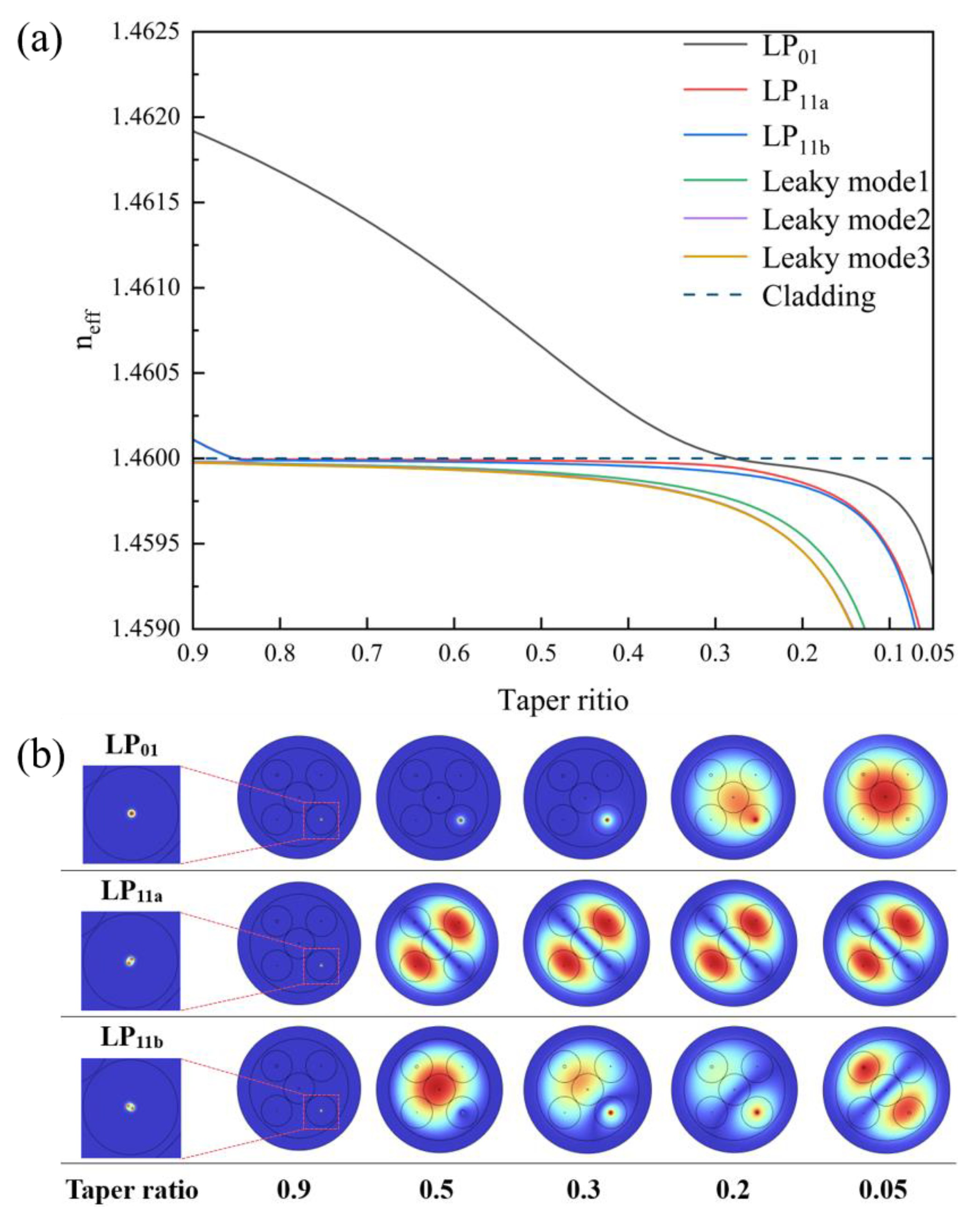
3.2. Mode Preservation at 1310 nm and 1550 nm

For the 1310 nm and 1550 nm bands, few-mode fibers (FMFs) with a numerical aperture (NA) of 0.10 were selected as input channels. Through structural optimization, the few-mode output port of the IM3PL was matched to the FMFs to enable mode-preserving transmissions at both wavelengths. Specifically, the few-mode port of the IM3PL was designed with a unified outer diameter and NA to ensure precise physical and modal matching with the input FMFs. This structural consistency helped prevent mode distortion or loss after transition through the tapered region.
In the input fiber array, the FMFs corresponding to 1310 nm and 1550 nm are indicated by the yellow and orange cores in Figure 1, respectively. The refractive indices of the FMF core and cladding were set to 1.4634 and 1.4600. To ensure a low-loss, closed-loop connection between the few-mode port of the lantern and the FMFs, the NA of the lantern’s few-mode port was also designed to be 0.10. During the thermal tapering process, the original fiber cladding became the core of the few-mode port, while the outer jacket transformed into the new cladding. According to the weakly guiding fiber NA formula N A = n c o r e 2 n c l a d 2 , n c o r e represents the refractive index of the new core (original fiber cladding, 1.4600), and n c l a d corresponds to the refractive index of the new cladding (the outer capillary). Based on this relationship, the calculated value of n c l a d is approximately 1.4566.
Figure 3 shows the variation in effective refractive indices at 1310 nm with different taper ratios in the IM3PL. L P 01 , L P 11 a , and L P 11 b modes at 1310 nm were individually launched into the corresponding 1310 nm FMF, and the propagation behavior was monitored under various taper ratios to evaluate whether low-loss mode-preserving transmission could be achieved at this wavelength.
As shown in Figure 3a, when the taper ratio is greater than 0.83, the 1310 nm FMF stably supports the L P 01 and L P 11 modes. As the taper ratio decreased, the L P 11 mode—with a lower effective refractive index—was the first to leak into the cladding. The L P 01 mode, having a higher effective index, remained guided until the taper ratio reached approximately 0.27, at which point it also leaked and transitioned into a guided mode in the newly formed few-mode waveguide. Figure 3b illustrates the mode field evolution at 1310 nm under different taper ratios. In the first row, the L P 01 mode injected into the FMF gradually expanded from the core. When the taper ratio reached 0.05, the mode evolved into a new L P 01 profile at the few-mode port, with the optical field uniformly distributed. In the second and third rows, the other two injected modes— L P 11 a and L P 11 b —also formed their respective modal patterns at the few-mode output when the taper ratio was reduced to 0.05.
These simulation results clearly demonstrate that, as the taper ratio decreases, the modal profiles progressively stabilize. When the taper ratio reached 0.05, the original L P 01 , L P 11 a , and L P 11 b modes injected from the 1310 nm FMF each evolved into well-defined and stable modal distributions at the few-mode output port of the IM3PL. This confirmed that the lantern structure preserved the original mode shapes throughout the taper transition, thereby achieving a low-loss, mode-preserving transmission at 1310 nm.
Similarly, the mode-preserving characteristics of the IM3PL at 1550 nm were verified through simulation. Figure 4a shows the variation in effective refractive indices of different modes as a function of the taper ratio. The simulation results indicate that the modal evolution behavior at 1550 nm closely resembles that at 1310 nm, with some differences in the coupling depth and leakage onset. These differences are primarily attributed to the longer wavelength at 1550 nm, which leads to a broader mode field radius and modified effective refractive indices. Under high taper ratios (greater than 0.85), both L P 01 and L P 11 modes remained well confined within the core of the input FMF. As the taper ratio decreased, the confinement weakened significantly, allowing the optical field to expand into the taper and evolve into new few-mode profiles. The L P 11 mode, having a lower effective index, coupled to the cladding earlier, while the L P 01 mode coupled at a taper ratio of approximately 0.28.
Figure 4b further illustrates the mode field evolution at 1550 nm for different input mode conditions. Specifically, in the first row, the L P 01 mode injected into the 1550 nm FMF gradually leaked from the core as the taper ratio decreased and eventually transformed into a new L P 01 mode at the few-mode output port. When the taper ratio reached 0.05, the L P 01 mode exhibited a uniform field distribution across the few-mode port, closely matching the original mode profile of the input FMF. In the second and third rows, the L P 11 a and L P 11 b modes evolved similarly into new L P 11 modes at the few-mode port under decreasing taper ratios, thereby maintaining compatibility with the original modal structure of the input FMFs.
These simulation results confirm that, during 1550 nm transmission through the IM3PL, the input L P 01 , L P 11 a , and L P 11 b modes were preserved in shape after propagating through the taper. In other words, the structure effectively supported the mode-preserving transmission at 1550 nm, similar to its performance at 1310 nm.
In summary, the simulation results demonstrate that the proposed IM3PL can achieve mode-selective excitation at 980 nm and mode-preserving transmission at both 1310 nm and 1550 nm. Moreover, all three wavelengths—980, 1310, and 1550 nm—were able to achieve their respective modal excitation or preservation under a common taper ratio of 0.05. The taper ratio of 0.05 was selected based on detailed modal evolution analyses at 980 nm, 1310 nm, and 1550 nm. Despite wavelength-dependent differences in effective indices and mode field diameters, the simulation results confirm that this taper profile enables low-loss and quasi-adiabatic transitions for all principal modes. Thus, using a unified taper ratio offers a balanced solution that ensures broadband modal compatibility while simplifying fabrication. This indicates that the device is capable of simultaneous multiplexing across the three bands. When the FMFs are connected to the few-mode output port of the lantern, the high-order transverse modes at 1310 nm and 1550 nm can propagate in a low-loss, closed-loop manner, making the IM3PL a promising solution for multiband multimode fiber systems.

4. Fabrication of the IM3PL Device

The input fiber array of the IM3PL consists of three 980 nm SMFs, one 1310 nm few-mode fiber (FMF), and one 1550 nm FMF. Following the simulation-based design, a standard 980 nm SMF with a 6 μm core diameter and 125 μm cladding diameter was used to excite the LP01 mode at the few-mode output port of the IM3PL. To excite the L P 11 a and L P 11 b modes, two additional 980 nm SMFs were pre-tapered to reduce their core diameters to 4.5 μm and 3.5 μm, respectively. These pre-tapered fibers were then incorporated into the input array as mode-selective excitation channels. The pre-tapering was performed using the flame brushing technique. After tapering, one fiber had a cladding diameter of approximately 97.2 μm and a core diameter of 4.5 μm, while the other had a cladding diameter of about 74.1 μm and a core diameter of 3.5 μm. The detailed fabrication parameters for these pre-tapered SMFs are summarized in Table 1. In future commercial applications, this pre-tapering step may be omitted by using commercially available 980 nm SMFs with different core diameters, thereby facilitating large-scale production. For the FMF inputs, commercial fibers were used. The 1310 nm FMF had a core diameter of 12 μm, and the 1550 nm FMF had a core diameter of 14 μm.
During the preparation phase of IM3PL fabrication, all input fibers were first stripped of their protective coatings and then arranged according to the specified configuration. The fibers were inserted into a low-refractive-index silica capillary tube (Innosep-TSP450660), followed by a two-step adiabatic tapering process using a high-temperature oxyhydrogen flame. The detailed parameters for this two-step tapering process—including gas flow rates, pulling speeds, and taper region lengths—are provided in Table 1. These parameters were refined through iterative experimentation to ensure efficient and stable optical coupling during transmission through the IM3PL.
After the tapering process was completed, the tapered fiber assembly was removed from the fiber fusion tapering system and cleaved at the region corresponding to a taper ratio of 0.05. This step defined the final structure of the IM3PL. The numerical aperture and end-face dimensions of the few-mode output port were designed to match those of the 1310 nm and 1550 nm FMFs, ensuring seamless optical mode transition.
Following fabrication, the IM3PL device was encapsulated to preserve its structural integrity. A photograph of the packaged device is shown in Figure 5. The encapsulated IM3PL maintained its intended configuration: the input side comprised a fiber array with three 980 nm SMFs (yellow), one 1310 nm FMF (blue), and one 1550 nm FMF (red). The few-mode output port was connected to a standard FMF, providing convenient access for subsequent modal analysis and characterization.

5. Transmission Characterization of the IM3PL Device

To evaluate the functional performance of the fabricated IM3PL, multimode field measurements were conducted across the designed wavelength bands. The primary goals of this experimental characterization were twofold: to confirm the controllable excitation of high-order modes at 980 nm and to verify the mode-preserving transmission behavior at 1310 nm and 1550 nm.

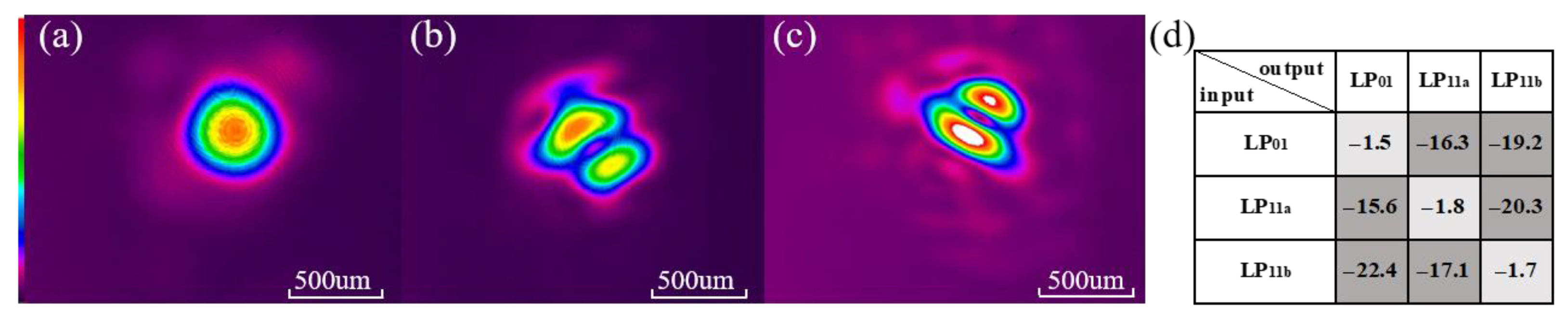
5.1. Mode-Selective Excitation at 980 nm

A 980 nm laser source (model to be specifiedHY-TPL-980-300-B-FA) was used to sequentially inject light into the three SMF channels with distinct core sizes in the input array. After propagation through the IM3PL, the output beam was emitted from the few-mode port, then collected and imaged using an infrared camera (Ophir SP620) through a 20× objective lens. Figure 6a–Figure 6c shows the output mode profiles observed at the few-mode port when light is injected into each of the three different 980 nm input fibers, clearly showing excitations of L P 01 , L P 11 a , and L P 11 b modes, respectively. The well-defined and distinguishable modal patterns confirm that the IM3PL enables precise mode-selective excitation at 980 nm, consistent with the simulation predictions and design intent. To evaluate the impact of polarization-dependent loss (PDL), we measured the back-to-back transmission matrix of the IM3PL under different input modes. As shown in Figure 6d, the unit is in dB; when LP01 is injected, the output powers of L P 01 , L P 11 a , and L P 11 b are −1.5 dB, −16.3 dB, and −19.2 dB, respectively. For the L P 11 a input, the corresponding outputs are −15.6 dB, −1.8 dB, and −20.3 dB; and for L P 11 b input, they are −22.4 dB, −17.1 dB, and −1.7 dB. These results indicate low intermodal crosstalk and good mode selectivity, suggesting that the IM3PL maintains high modal fidelity under varying polarization states.
Although the direct quantification of PDL was limited by the absence of one-to-one modal mapping at the input and output, the stable transmission power and consistently clear mode profiles observed across polarization states imply that PDL has a minimal influence on performance. For scenarios requiring enhanced polarization robustness, polarization-maintaining fibers (PMFs) can be used for input excitation, and symmetric taper structures can be adopted during IM3PL fabrication to further suppress polarization sensitivity.

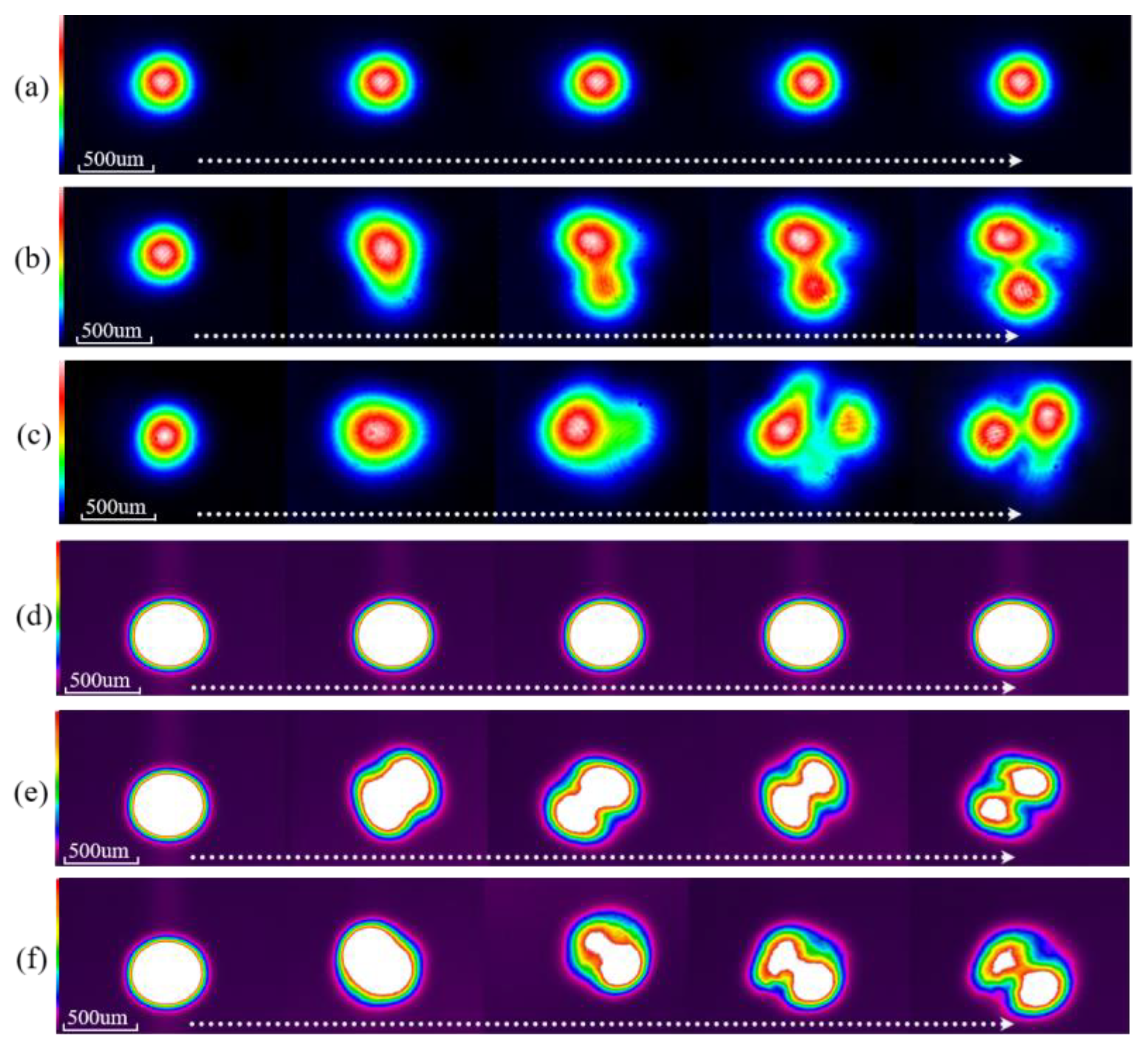
5.2. Mode Preservation at 1310 nm and 1550 nm

For the IM3PL to serve as a practical component in ring-cavity high-order-mode fiber lasers, it is essential that the few-mode fibers (FMFs) within the lantern, as well as the few-mode output port, are structurally and optically matched. This matching enables the formation of a closed-loop FMF cavity, supporting stable mode circulation. Therefore, the ability of the IM3PL to preserve the spatial profiles of different high-order modes at 1310 nm and 1550 nm is critical to the realization of a dual-band, multimode photonic lantern system. As one of the key innovations of the proposed three-band IM3PL, its mode-preserving capability at 1310/1550 nm was experimentally verified.
To verify the mode-preserving capability of the IM3PL at 1310 nm and 1550 nm, it was essential to first generate and control the excitation of specific modes at the input end of the few-mode fibers (FMFs). A fiber-offset excitation scheme was employed for this purpose. The 1310 nm or 1550 nm laser was first coupled into a single-mode fiber (SMF) corresponding to the target wavelength. By precisely adjusting the lateral offset between the cores of the SMF and FMF, and applying polarization control, different guided modes—including L P 01 , L P 11 a , and L P 11 b —could be selectively excited.
When the SMF was aligned coaxially with the FMF, the fundamental L P 01 mode was excited. As the lateral offset was gradually increased in orthogonal directions, and the input polarization was fine-tuned, the excitation of L P 11 a and L P 11 b modes was achieved. The resulting mode evolutions at the FMF output are shown in Figure 7a–c for the 1310 nm configuration, illustrating how the modal field transitions from the fundamental to higher-order modes as the input offset varies. Similarly, Figure 7d–f show the corresponding mode evolution process at 1550 nm, demonstrating the consistent and repeatable excitation of high-order modes via offset launching.
Each excited mode at 1310 nm or 1550 nm was then injected into the corresponding FMF input of the IM3PL. The modal profiles at the few-mode output port were recorded using wavelength-specific infrared cameras (Beam 2000/1550 and Beam 2000/1310). As shown in Figure 8, the L P 01 , L P 11 a , and L P 11 b modes maintained their distinct shapes upon exiting the IM3PL, closely matching their respective input profiles. These results confirm that the IM3PL provides low-loss and independent transmission paths for different high-order modes, thus validating its mode-preserving capability at both 1310 nm and 1550 nm.

6. Conclusions

In conclusion, this work demonstrates the feasibility of employing a single photonic lantern to achieve multiband multi-mode coupling within a compact and scalable device. Through wavelength-selective high-order-mode excitation at 980 nm and low-loss mode-preserving transmission at 1310 nm and 1550 nm, the proposed device demonstrates the versatility of photonic lanterns in supporting both spatial and spectral multiplexing. These results underline the potential of this new photonic lantern design to support advanced mode-division multiplexed communications. It also provides a foundation for developing multiband high-order-mode fiber lasers, contributing to the realization of compact and integrated photonic systems across multiple wavelength bands.

Author Contributions

Conceptualization, L.Z.; methodology, T.Y. and Y.C.; validation, T.Y. and L.Z.; formal analysis, L.Z.; investigation, L.Z. and J.T.; writing—original draft preparation, T.Y. and L.Z. All authors have read and agreed to the published version of the manuscript.

Funding

This research was funded by the National Natural Science Foundation of China (62401499, 62105279); the Applied Basic Research Foundation of Yunnan Province (202401CF070074, 202201AU070047); the Major Science and Technology Projects and Key Research and Development Program of Yunnan Province (202403ZC380002); and Yunnan Provincial Department of Education Scientific Research Fund Project (2025Y0668).

Institutional Review Board Statement

Not applicable.

Informed Consent Statement

Not applicable.

Data Availability Statement

The original contributions presented in this study are included in the article. Further inquiries can be directed to the corresponding authors.

Conflicts of Interest

The authors declare no conflicts of interest.

References

  1. Richardson, D.; Fini, J.; Nelson, L. Space-division multiplexing in optical fibres. Nat. Photonics 2013, 7, 354–362. [Google Scholar] [CrossRef]
  2. Winzer, P.J.; Neilson, D.T.; Chraplyvy, A.R. Fiber-optic transmission and networking: The previous 20 and the next 20 years [Invited]. Opt. Express 2018, 26, 24190–24239. [Google Scholar] [CrossRef] [PubMed]
  3. Bozinovic, N.; Yue, Y.; Ren, Y.; Tur, M.; Kristensen, P.; Huang, H.; Willner, A.E.; Ramachandran, S. Terabit-Scale Orbital Angular Momentum Mode Division Multiplexing in Fibers. Science 2013, 340, 1545–1548. [Google Scholar] [CrossRef] [PubMed]
  4. Mori, T.; Sakamoto, T.; Wada, M.; Yamamoto, T.; Nakajima, K. Few-mode fiber technology for mode division multiplexing. Opt. Fiber Technol. 2017, 35, 37–45. [Google Scholar] [CrossRef]
  5. Zervas, M.N.; Codemard, C.A. High Power Fiber Lasers: A Review. IEEE J. Sel. Top. Quantum Electron. 2014, 20, 219–241. [Google Scholar] [CrossRef]
  6. Huang, Y.; Shi, F.; Wang, T.; Liu, X.; Zeng, X.; Pang, F.; Wang, T.; Zhou, P. High-order mode Yb-doped fiber lasers based on mode-selective couplers. Opt. Express 2018, 26, 19171–19181. [Google Scholar] [CrossRef]
  7. Richardson, D.J.; Nilsson, J.; Clarkson, W.A. High power fiber lasers: Current status and future perspectives [Invited]. J. Opt. Soc. Am. B 2010, 27, B63–B92. [Google Scholar] [CrossRef]
  8. Zhou, Q.; Lu, Y.; Li, C.; Chai, J.; Zhang, D.; Liu, P.; Zhang, J.; Jiang, Z.; Liu, W. Transmission Matrix-Inspired Optimization for Mode Control in a 6 × 1 Photonic Lantern-Based Fiber Laser. Photonics 2023, 10, 390. [Google Scholar] [CrossRef]
  9. Birks, T.A.; Gris-Sánchez, I.; Yerolatsitis, S.; Leon-Saval, S.G.; Thomson, R.R. The photonic lantern. Adv. Opt. Photon. 2015, 7, 107–167. [Google Scholar] [CrossRef]
  10. Puttnam, B.J.; Rademacher, G.; Luís, R.S. Space-division multiplexing for optical fiber communications. Optica 2021, 8, 1186–1203. [Google Scholar] [CrossRef]
  11. Leon-Saval, S.G.; Birks, T.A.; Bland-Hawthorn, J.; Englund, M. Multimode fiber devices with single-mode performance. Opt. Lett. 2005, 30, 2545–2547. [Google Scholar] [CrossRef]
  12. Leon-Saval, S.G.; Argyros, A.; Bland-Hawthorn, J. Photonic lanterns: A study of light propagation in multimode to single-mode converters. Opt. Express 2010, 18, 8430–8439. [Google Scholar] [CrossRef]
  13. Dana, Y.; Garcia, Y.; Kukin, A.; Dallachiesa, L.; Guerrier, S.; Fontaine, N.K.; Marom, D.M. Free-standing microscale photonic lantern spatial mode (De-)multiplexer fabricated using 3D nanoprinting. Light Sci. Appl. 2024, 13, 126. [Google Scholar] [CrossRef]
  14. Zhou, W.; Zhang, Z.; Chen, H.; Tsang, H.K.; Tong, Y. Ultra-compact and efficient integrated multichannel mode multiplexer in silicon for few-mode fibers. Laser Photonics Rev. 2024, 18, 2300460. [Google Scholar] [CrossRef]
  15. Spaleniak, I.; Gross, S.; Jovanovic, N.; Williams, R.J.; Lawrence, J.S.; Ireland, M.J.; Withford, M.J. Multiband processing of multimode light: Combining 3D photonic lanterns with waveguide Bragg gratings. Laser Photonics Rev. 2014, 8, L1–L5. [Google Scholar] [CrossRef]
  16. Liang, J.; Ye, J.; Ma, X.; Lu, Y.; Li, J.; Xu, J.; Chen, Z.; Leng, J.; Jiang, Z.; Zhou, P. Mode division multiplexing reconstructive spectrometer with an all-fiber photonics lantern. Front. Optoelectron. 2024, 17, 23. [Google Scholar] [CrossRef]
  17. Velázquez-Benítez, A.M.; Antonio-López, J.E.; Alvarado-Zacarías, J.C.; Fontaine, N.K.; Ryf, R.; Chen, H.; Hernández-Cordero, J.; Sillard, P.; Okonkwo, C.; Leon-Saval, S.G.; et al. Scaling photonic lanterns for space-division multiplexing. Sci. Rep. 2018, 8, 8897. [Google Scholar] [CrossRef] [PubMed]
  18. Leon-Saval, S.G.; Fontaine, N.K.; Salazar-Gil, J.R.; Ercan, B.; Ryf, R.; Bland-Hawthorn, J. Mode-selective photonic lanterns for space-division multiplexing. Opt. Express 2014, 22, 1036–1044. [Google Scholar] [CrossRef] [PubMed]
  19. Lu, Y.; Jiang, Z.; Liu, W.; Chen, Z.; Jiang, M.; Zhou, Q.; Zhang, J. Laser Mode Control in Fiber with Core Diameter of 30 μm Based on 3 × 1 Photonic Lantern. Acta Opt. Sin. 2021, 41, 1736001. [Google Scholar] [CrossRef]
  20. Ryf, R.; Randel, S.; Gnauck, A.H.; Bolle, C.; Sierra, A.; Mumtaz, S.; Esmaeelpour, M.; Burrows, E.C.; Essiambre, R.-J.; Winzer, P.J.; et al. Mode-Division Multiplexing Over 96 km of Few-Mode Fiber Using Coherent 6 × 6 MIMO Processing. J. Light. Technol. 2012, 30, 521–531. [Google Scholar] [CrossRef]
  21. Fontaine, N.K.; Doerr, C.R.; Mestre, M.A.; Ryf, R.R.; Winzer, P.J.; Buhl, L.L.; Sun, Y.; Jiang, X.; Lingle, R. Space-Division Multiplexing and All-Optical MIMO Demultiplexing Using a Photonic Integrated Circuit, OFC/NFOEC; IEEE: Los Angeles, CA, USA, 2012; pp. 1–3. [Google Scholar]
  22. Liu, Z.; Zhang, S.; Qian, Z.; Gao, Z.; Tang, M.; Zhao, L. Intelligent few-mode multi-wavelength fiber laser based on photonic lantern comb filter. Opt. Laser Technol. 2025, 180, 111501. [Google Scholar] [CrossRef]
  23. Huang, B.; Li, M.; Ping, H.; Wang, J.; Li, X.; Shao, X. Impact of Geometric Input Fibers’ Core Positioning on the Adiabaticity of Photonic Lanterns. Photonics 2024, 11, 222. [Google Scholar] [CrossRef]
  24. Lu, S.; Xiao, Y.; Jiang, X. Research on Fused Taper All Fiber Multi-Mode Multiplexer/De-Multiplexer. Chin. J. Lasers 2018, 45, 0706002. [Google Scholar] [CrossRef]
  25. Zhao, L.; Li, W.; Chen, Y.; Zhao, E.; Tang, J. Design of Self-Matching Photonic Lantern for High-Order Transverse-Mode Laser Systems. Photonics 2024, 11, 208. [Google Scholar] [CrossRef]
Figure 1. Schematic diagram of the IM3PL.
Photonics 12 00729 g001
Figure 2. (a) Variation in effective refractive indices at 980 nm in the IM3PL structure; (b) simulated mode field evolution at 980 nm under different taper ratios.
Photonics 12 00729 g002
Figure 3. (a) Variation in effective refractive indices for different modes at 1310 nm in the IM3PL; (b) simulated mode field evolution of L P 01 , L P 11 a , and L P 11 b modes at 1310 nm under different taper ratios in the IM3PL.
Photonics 12 00729 g003
Figure 4. (a) Variation in effective refractive indices for different modes at 1550 nm in the IM3PL; (b) simulated mode field evolution at 1550 nm under different taper ratios.
Photonics 12 00729 g004
Figure 5. Photograph of the fabricated IM3PL device.
Photonics 12 00729 g005
Figure 6. (ac) Near-field mode profiles at the few-mode output port of the IM3PL, from left to right:   L P 01 , L P 11 a , and L P 11 b modes; (d) back-to-back transmission matrix of the IM3PL.
Photonics 12 00729 g006
Figure 7. Generation of high-order modes via fiber core-offset excitation: (a) L P 01 at 1310 nm; (b) transition from the L P 01 to L P 11 a mode at 1310 nm; (c) transition from the L P 01 to L P 11 b mode at 1310 nm; (d) L P 01 at 1550 nm; (e) transition from the L P 01 to L P 11 a mode at 1550 nm; (f) transition from the L P 01 to L P 11 b mode at 1550 nm.
Photonics 12 00729 g007
Figure 8. Near-field mode profiles at the few-mode output port of the IM3PL: (ac) L P 01 , L P 11 a , and L P 11 b modes at 1310 nm, from left to right; (df): L P 01 , L P 11 a , and L P 11 b modes at 1550 nm, from left to right.
Photonics 12 00729 g008
Table 1. Tapering parameters for the fabrication of the IM3PL device.
Processing StageH2/O2 Flow Rate (SCCM)Pulling Speed (μm/s)Pulling Length (μm)Core Diameter
After Tapering (μm)
Taper Waist Diameter (μm)
Pre-tapered 980 nm SMFsPre-tapered 980 nm SMF1190/08090004.5/97.2/
Pre-tapered 980 nm SMF2190/08010,0003.5/74.1/
Two-Step Tapering for IM3PL FabricationFirst-stage Tapering220/6022015,000/151.8
Second-stage Tapering160/022050,000/16.7
Disclaimer/Publisher’s Note: The statements, opinions and data contained in all publications are solely those of the individual author(s) and contributor(s) and not of MDPI and/or the editor(s). MDPI and/or the editor(s) disclaim responsibility for any injury to people or property resulting from any ideas, methods, instructions or products referred to in the content.

