1. Introduction
Displacement is a fundamental geometric parameter, and its accurate measurement is crucial in various fields [
1]. With the rapid development of nanotechnology, the demand for precise micro-displacement measurement techniques in areas such as ultra-precision machining, scientific research, and high-precision sensing is increasing [
2,
3].
Current high-precision micro-displacement measurement methods can be broadly categorized into non-optical and optical techniques [
4,
5]. Non-optical methods include electrical measurement and microscopic techniques, which typically have a limited measurement range and are suitable only for short-distance measurements on the order of tens of nanometers to micrometers. Moreover, these methods often rely on optical calibrations. By contrast, laser interferometry, a representative optical method, offers advantages such as a wide measurement range and high accuracy. Moreover, it can directly trace measurements to the wavelength of light. As a result, laser interferometry has been widely used in precision measurements, such as displacement [
6,
7]. Various types of laser interferometers have been reported in the literature, including Mach–Zehnder interferometers (MZIs) [
8,
9], Michelson interferometers (MIs) [
10,
11], and Fabry–Perot interferometers (FPIs) [
12,
13]. MZIs and MIs have been widely applied to measure dynamic strain, temperature, and other parameters. However, their operation relies on an additional reference arm, which must be isolated from both the measured parameters and the surrounding environment [
14]. Therefore, the optical path difference between the reference and measurement arms should be relatively stable to achieve high-precision micro-displacement measurements. Additionally, an interferometric system should possess a certain degree of self-calibration capability to ensure it can compensate for system errors due to internal disturbances, thereby significantly enhancing measurement stability and accuracy [
15]. By contrast, an FPI uses a common-path configuration, comprising the end face of an optical fiber and the reflective surface of a movable target, thus effectively separating the reference and measurement arms while sharing the same optical path. This design inherently suppresses disturbances within the system and significantly improves displacement measurement accuracy, outperforming separate-path interferometers by several orders of magnitude [
16,
17].
Lawall [
18] proposed using a high-finesse FPI for micro-displacement measurements. In this approach, the comb-like transmission peaks of the high-finesse Fabry–Perot (F–P) cavity are formed by multiple reflections and interferences within the cavity, implying that extremely high resolution can be achieved, but with reduced measurement speed. Moreover, high-finesse F–P cavities impose strict requirements on the parallelism of reflective surfaces, increasing the complexity of optical system alignment and adjustment and placing stringent demands on the stability of large-range motion platforms. Thurner [
19,
20] proposed a micro-displacement measurement method based on a low-finesse F–P cavity. Under near-orthogonal interference conditions, with a finesse of approximately 0.5, combined with quadrature demodulation techniques, this method enables high-precision micro-displacement measurement. However, the proposed design adopts a folded F–P cavity structure with a finesse of approximately 0.615, deviating from the ideal orthogonal interference condition with finesse of 0.5. Additionally, the structure has a mirror angle tolerance exceeding ±0.2°; such a wide angle variation causes discrepancies between the measured results and actual displacement, requiring further error correction. However, this correction process introduces new errors. Thus far, no systematic design method for low-finesse FPIs has been proposed. Therefore, designing a structurally optimized F–P cavity that facilitates the realization of ideal orthogonal interference with a finesse of 0.5 while effectively addressing the higher-order reflection issues caused by the high reflectivity of the target surface would significantly enhance measurement accuracy. Such a design has substantial research value and promising potential applications.
This study proposes a low-finesse FPI design that employs a high-reflectivity spherical mirror and the end face of a fiber collimator as the reflective surface of the cavity. By leveraging beam divergence characteristics and geometric parameters, a F-P cavity structure with a finesse of approximately 0.5 is quantitatively designed, enabling a simplified implementation that does not require angular alignment. By leveraging the advantages of spherical reflection, this design relaxes the precision requirements for reflectivity, effectively mitigating the influence of multiple reflections. The optical alignment process is simplified by eliminating the need for precise angular adjustment of the reflective surfaces, as required in conventional methods. Thus, the incident beam must only be roughly aligned with the center of the reflective sphere, significantly lowering implementation difficulty. A theoretical analysis shows that fixing the receiving field angle and the beam radius of the fiber collimator helps meet the requirements for a low-finesse F–P cavity, with ideal orthogonal interference achievable simply by properly designing the radius of the reflective sphere. The experimental results demonstrate that, for various cavity lengths, the average finesse values of the interference spectra obtained using fiber collimators 1 and 2 are 0.496 and 0.502, respectively, close to the theoretical design value of 0.5, thereby validating the feasibility of the proposed design.
2. Analysis of a Low-Finesse F–P Cavity Based on a Reflective Sphere
In an FPI cavity, finesse [
21], defined as the ratio of the phase difference between adjacent resonance peaks to the linewidth of a single resonance peak, characterizes the sharpness of the resonance peaks. Finesse can be expressed as
The reflection coefficients of the fiber end face and the opposite reflective surface are denoted
and
, respectively, and their corresponding reflectivities are represented as follows. The reflectivities of the fiber end face and the opposite surface are given by
and
, where
and
. Here,
and
denote the complex conjugates of the reflection coefficients, corresponding to the fiber end face and the reflective sphere surface, respectively. Theoretically, to achieve high-precision micro-displacement measurements, ideal quadrature interference is necessary, which requires that the spectral response of the FPI approximates a sinusoidal curve. Under these conditions, the required finesse is approximately 0.5. A typical value of
is approximately 0.036. From Equation (
1), when
is approximately 0.02, the finesse of the F–P cavity approaches 0.5.
However, achieving such a low reflectivity in practical designs is challenging. Moreover, ensuring that the remaining 98% of the transmitted light is not reflected into the cavity through other interfaces, thereby potentially interfering with the resonant cavity, is challenging. However, conventional F–P cavities are typically formed using planar mirrors, and the reflective surfaces should be perfectly perpendicular to the optical axis, rendering optical alignment extremely challenging.
To address these issues, we propose a novel low-finesse F–P cavity based on a reflective sphere, as shown in
Figure 1. The optical signal is emitted from the tail fiber of the optical coupler, collimated using a fiber collimator, and projected into free space. The resulting collimated beam is then reflected by a high-reflectivity sphere, penetrating the fiber again through the collimator. In this configuration, an F–P cavity is formed between the end cap of the collimator and the reflective sphere.
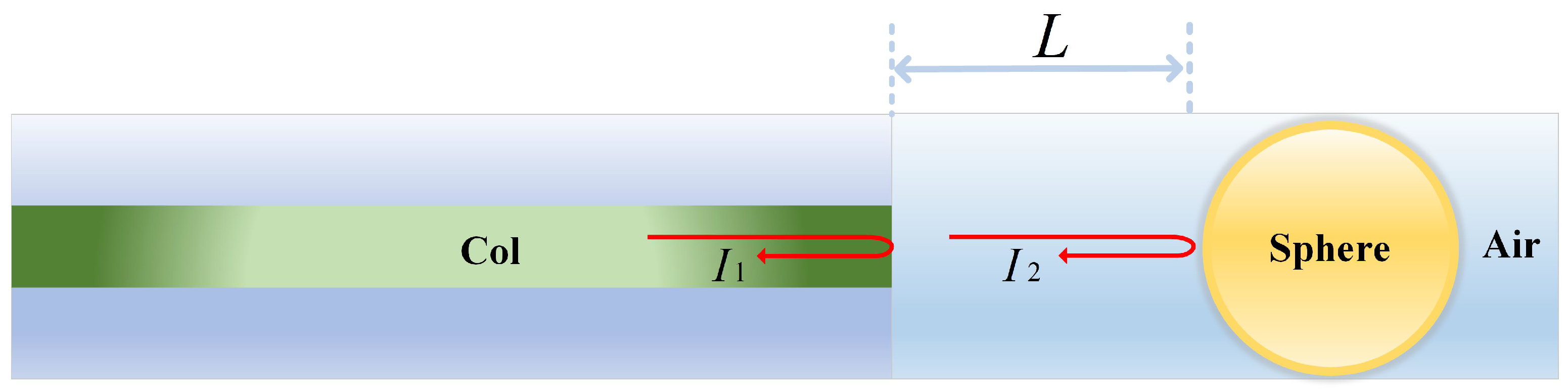
The reflection process of a sphere is illustrated in
Figure 2. When a collimated parallel beam is incident on the spherical reflector, only the portion of the reflected light that falls within the system’s acceptance angle
can be effectively collected and contribute to interference. Due to the curvature of the spherical surface, the reflected beam undergoes spatial divergence, causing a significant portion of the light to fall outside the collection range, thereby resulting in an effective reflectivity that is much lower than the actual surface reflectivity of the sphere. Geometric analysis shows that for a spherical surface with a divergence angle of
, the reflected beam has a divergence angle of
. Assuming the acceptance angle of the optical system is
, only the portion of the light satisfying
can be effectively received. Accordingly, the radius of the receivable light spot can be expressed as
Here,
r represents the radius of the reflected beam that can be received by the collimator, and
D denotes the diameter of the reflective sphere. We define the ratio of the collected reflected light area to the total area of the incident beam on the spherical reflector as the effective reflectivity. Let
be the radius of the beam incident on a sphere, when the reflectivity of the sphere is 0.02, the area of the reflected beam relative to the incident beam is 0.02. Therefore, the beam radius must satisfy the following condition:
For
, i.e., when the radius of the incident beam is 7.1 times larger than that of the receivable spot, the effective reflectivity reaches 0.02. Therefore, in the practical construction of a low-finesse F–P cavity, different models of collimators correspond to different values of
and output beam radius
. Once a specific collimator is selected, the values of
and
are known. Given that
, Equation (
2) can then be used to determine the required radius of the reflective sphere. Combined with the previously derived reflectivity condition, an appropriate sphere can be designed accordingly, enabling the construction of an F–P cavity with a finesse of 0.5.
The light emitted from the collimator into the F–P cavity can be expressed as [
22]
Here,
represents the laser frequency,
t denotes time,
is the initial phase of the light, and
is the optical field amplitude. The reflection coefficient of the collimator end face is denoted as
, and its transmission coefficient is
. The reflection coefficient of the metallic sphere is represented by
.
Figure 3 shows the optical transmission path in the designed low-finesse F–P cavity. The incident light is partially reflected at
, resulting in a backward-propagating wave
, and the forward-propagating light entering the cavity along the x-axis is denoted
. These components are expressed as follows:
After a single round-trip transmission through the F-P cavity, a phase shift is introduced as
Here,
L denotes the length of the F–P cavity, and
is the wavelength of the laser. After one reflection and one transmission, the forward-propagating light
generates a backward-propagating component
along the x-direction. Similarly, after two reflections,
produces a forward-propagating component
along the x-direction. These components can be expressed as
After undergoing one reflection and one transmission, component
generates a backward-propagating wave
along the x-direction. Subsequently,
undergoes two additional reflections to generate a forward-propagating wave
along the x-direction. These components can be expressed as
Similarly,
and
can be expressed as
Here,
M is the number of optical paths. If the interference between
and
is considered, the resulting first-order interference field is denoted as
, and the corresponding interference intensity is represented by
:
If the interference among components
,
, and
is considered, the resulting second-order interference field is denoted
, and the corresponding interference intensity is denoted
:
When , the amplitude coefficient of the light component is . Therefore, at , only the first- and second-order interference components are considered, whereas the third- and higher-order components can be neglected.
First, the interference characteristics of the spherical reflection in the F–P cavity were analyzed through theoretical modeling and numerical simulation.
Figure 4 shows the simulated results for both the first- and second-order interference patterns. In this study, the incident light is set with an amplitude
, an initial phase
, and a cavity length
mm. The reflectivity coefficient is set as
, and the transmittance is
. As shown in
Figure 4a, when the reflectivity
increases to 0.8, the spectral shape of the second-order interference intensity
deviates significantly from a sinusoidal form owing to the overlapping of multiple reflected beams. By contrast,
Figure 4b shows that when the reflectivity
is reduced to 0.02 (corresponding to the spherical reflector used in this design), the spectral curves of the first- and second-order interference intensities
and
exhibit minimal differences and are almost identical.
This analysis indicates that when the reflectance at both ends of the F–P cavity is sufficiently low, the influence of multiple reflections on the transmission spectrum is negligible. In terms of the average intensity of the transmitted spectrum, the intensity of higher-order reflected beams is minimal and can be considered negligible in numerical simulations. The use of a reflective sphere is advantageous in that its high reflectivity eliminates the need for stringent precision in the reflectance value, significantly simplifying the implementation of a low-finesse F–P cavity. Simultaneously, the effect of high-order reflections is significantly reduced, thereby improving the measurement accuracy of the system. Moreover, when the acceptance angle of the beam receiver and the radius of the output beam are fixed, the finesse of the F–P cavity can be flexibly adjusted simply by appropriately designing the diameter of the reflective sphere.
3. Experimental Results and Analysis
The experimental setup is shown in
Figure 5. The system connects an erbium-doped fiber amplifier (EDFA), a fiber collimator, and an optical spectrum analyzer (OSA) via a circulator. The spontaneous emission spectrum of the EDFA serves as a broadband light source for the system. Broadband light enters the circulator through port 1 and exits through port 2 to the fiber collimator. Approximately 4% of the incident light is reflected at the end face of the collimator, whereas the remaining transmitted light passes through the end face and is incident on the surface of the reflective sphere. The light reflected by the sphere then travels back along the same path to the collimator, where it interferes with the light reflected from the end face of the collimator. The resulting interference signal exits the circulator through port 3, and its spectral characteristics are analyzed using the OSA.
The experimental setup is shown in
Figure 6. To enable precise optical alignment, the fiber collimator and reflective sphere are mounted on adjustment stages with six degrees of freedom. The optical alignment process is significantly simplified using a spherical surface as the reflector. The beam needs only to be roughly aligned with the center of the reflective sphere, without requiring precise angular adjustment of the reflective surface, thereby satisfying the design requirements of a low-finesse F–P cavity.
Given that the resolution of the optical spectrum analyzer is 0.05 nm, a relatively short working distance is selected for the experiment. Considering the flatness of the spontaneous emission spectrum of the EDFA at approximately 1550 nm, the measurement is conducted within this spectral range to easily observe the interference characteristics. Two types of fiber collimators were used in the experiment. The receiving angle and output beam radius of the collimators were 0.6° and 0.1 mm and 0.85° and 0.075 mm, respectively. Based on theoretical calculations, to achieve a low-finesse F–P cavity with a finesse of 0.5, the required diameters of the reflective spheres should be 10.7 and 5.5 mm. The relevant parameters of the experimental components are listed in
Table 1.
Under fixed reflective sphere diameters, the working distance between the spherical surface and collimator was varied. Five working distances (4, 5, 6, 7, 8, 9, 10, 11 and 12 mm) were selected for the experiment by adjusting the separation L between the sphere and collimator.
Figure 7a and
Figure 7b show the normalized interference spectra obtained using collimators 1 and 2, respectively. The experimental results indicate that as L increases, both the free spectral range (FSR) and 3 dB bandwidth exhibit a decreasing trend. This observation aligns with theoretical expectations, as the FSR is inversely proportional to the cavity length in an F–P interferometer. As
L increases, the fringe spacing decreases, thereby decreasing both the FSR and bandwidth. Analyzing the interference spectra under each experimental condition can help obtain the corresponding FSR and finesse F, where the finesse is defined as the ratio of the FSR to the 3 dB bandwidth.
Figure 8a shows the measured finesse values of the F–P cavities at different working distances. The average finesse values obtained from the interference spectra are 0.496 and 0.502 for Collimators 1 and 2, respectively. These results align with the theoretical design value of 0.5, confirming that the experimental implementation satisfies the design requirements for a low-finesse F–P cavity.
Figure 8b illustrates the relationship between the FSR and cavity length, indicating that the FSR decreases with increasing cavity length. The experimental results are consistent with the theoretical calculations, further validating the accuracy and effectiveness of the low-finesse F–P cavity design. Summarily, the measured finesse values confirmed that the proposed design satisfied the performance requirements of a low-finesse F–P cavity. The interference spectra obtained using both types of collimators exhibited finesse values close to the ideal orthogonal interference value of 0.5. This result demonstrates that when the receiving angle and output beam radius of the fiber collimator are fixed, designing the diameter of the reflective sphere to satisfy the finesse requirement of the F–P cavity and achieve ideal orthogonal interference is sufficient.


