Abstract
A stable microwave signal transmission system for a distributed system that is capable of simultaneous downloads at multiple arbitrary nodes within the optical path is proposed. The download module, which is based on optical circulators and optical couplers, can be inserted at any node position within the transmission optical path to complete the downloading of frequency-synchronization signals. Experimentally, a distributed frequency-synchronization system with multiple download nodes is demonstrated over 40 km of optical fiber. Experimental results show that the signal has been downlink-transferred from different download modules with the standard deviation of phase jitter being 1°@10 GHz at 1 h through 40-km optical fiber. Moreover, the standard deviation of phase jitter between downloaded signals from any two download modules is also better than 1°@10 GHz at 1 h. In addition, the Allan Deviation is better than @1 h for the download module.
1. Introduction
Time–frequency synchronization with high precision is the core requirement of modern distributed electronic devices. As a crucial element of time–frequency synchronization, phase synchronization significantly impacts system performance in specific scenarios with stringent requirements for signal-processing accuracy, such as time-service systems [1], array-measurement systems [2,3], integrated sensing and communication systems (ISACs) [4], and so on. Consequently, how to distribute the frequency-synchronization signals to each target within the transmission optical path and ultimately achieve the time–frequency synchronization of the entire system has become a hot topic of current research.
Optical fiber is characterized by high reliability, high precision, and low loss. It can overcome the effects of air disturbance and has gradually developed into an established transmission medium [5,6,7]. However, because optical fibers are sensitive to the environment, they must undergo phase pre-compensation to improve the accuracy of time–frequency synchronization [8,9]. Leveraging the characteristic that frequency-multiplied signals generate multiple phase shifts after transmission through the optical path, passive control of signal phase has become an effective approach [9,10]. Meanwhile, in [11], the amplitude modulation of carrier signals is employed. The phase relationship between different frequency components after transmission is ingeniously utilized to achieve synchronous signal downloading with phase-locking at the remote site. However, these schemes only support point-to-point transmission and cannot meet the requirements of signal download in distributed systems. Therefore, numerous solutions that target time–frequency synchronization in distributed systems have been proposed.
To enhance the system’s adaptability to distributed applications, a multi-channel distributed synchronization system based on a single clock source is subsequently proposed. Specifically, a multi-wavelength passive phase feedback control transmission architecture is proposed [12], which integrates laser arrays with wavelength-division multiplexing (WDM) technology and enables phase-locked signal transmission to each remote site in the distributed system. Meanwhile, multiple sets of signal transmission systems are constructed based on the number of devices to be transmitted [13,14], thereby achieving synchronization among an arbitrary number of devices. Although these schemes perform excellently, when synchronizing multi-endpoint devices, multiple different wavelength lasers or phase-locked modules must be installed, resulting in relatively high costs. To further simplify the system, a scheme based on an optical switch (OS) is proposed in [15,16], which employs an OS switching mechanism to enable phase feedback regulation for multiple remote sites. However, it still requires a dedicated single-mode optical fiber (SMF) for each remote site, and the total number of supported remote sites is limited by the port count of the OS. Consequently, there is an urgent need to develop a solution that can serially connect an arbitrary number of transmission nodes. Moreover, it needs to operate over a single optical fiber while ensuring phase-stable frequency distribution.
In [17,18], an optical coupler (OC) and WDM are used to achieve time–frequency synchronization and signal downloading randomly within the optical path. However, the OC-based scheme suffers from poor flexibility, failing to dynamically adjust bidirectional optical power on demand. It often requires integrating components such as an erbium-doped fiber amplifier (EDFA) into the download module to compensate for optical power, which additionally increases the system’s complexity. However, the stable control of the transmission optical path is mostly achieved by controlling optical delay line (ODL) or phase shifter (PS), which inevitably presents problems of exceeding the control range. Moreover, although there have been cases of using a PS to achieve a rapid reset process, the reset time still depends on its adjustment speed. Furthermore, when the adjustment range is large, the reset process time will be further prolonged. Thus, how to reduce the reset time of the phase delay control module has become one of the key factors in improving transmission stability.
To further optimize distributed time–frequency synchronization systems, we propose a novel method for microwave signal downloading at any number of positions within the transmission optical path. The phase jitter of the system can be measured using an IQ mixer (IQMIX), which serves as the feedback signal to control the phase delay of the ODL control module to maintain the stability of the transmission optical path. Additionally, a parallel ODL control module is proposed to expand the scope of control. Moreover, the parallel ODL control module can effectively solve the issue of limited control range and significantly shorten the reset time without relying on the move length of the ODL. Furthermore, to ensure the stability of downloaded signals, the download module is designed using a dual circulator (CIR) and OC structure. This allows the splitting ratio of the bidirectional optical path to be set according to the inserting position. Taking an experiment over 40 km of optical fiber within 1 h, the downloaded signal frequency’s Allan Deviation is better than 10−12. Moreover, the signal has been downlink-transferred from different download modules with the standard deviation of phase jitter being only 1°@10 GHz at 1 h.
2. Experimental Principle
2.1. Principle of the Download Module
The basic scheme of the download module, which is composed of two circulators and two optical couplers, is shown in Figure 1.
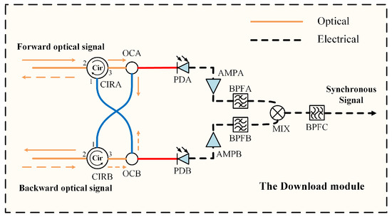
Figure 1.
Basic scheme of the download module. CIRA, CIRB: circulators; OCA, OCB: optical coupler; PDA, PDB: photodetector; AMP1, AMP2: amplifier; BPFA, BPFB, BPFC: bandpass filter; MIX: mixer.
For the download module, it is necessary to ensure symmetry of devices in the forward and backward optical signal-processing branches as much as possible, and simplify the internal structure to reduce phase jitter introduced by itself. The traditional dual-coupler scheme has a fixed split ratio, poor flexibility, and usually requires separate power amplification for the branches, making it difficult to ensure symmetry. In contrast, our scheme adopts a combined structure of CIR and OC, whose branch split ratio can be flexibly adjusted according to the actual optical power. Meanwhile, in the transmission optical path, as the number of download modules increases, higher requirements are imposed on the power of bidirectional optical signals. Since this optical amplifier component is located in the transmission optical path, the phase jitter introduced by EDFA can be actively compensated through adjustments of the ODL, thereby ensuring the overall stability of the transmission optical path. Thus, it avoids impact on the internal structure of the download module and achieving both flexibility and functional stability.
Assume that the forward optical signal carries a signal whose frequency is and phase is when it reaches the CIRA, whereas the phase of the backward optical signal is when it reaches CIRB in the download module. The forward optical signal subsequently enters Port 2 of CIRA and exits Port 3, and is split into two paths via OCA. The signal along one of these paths undergoes photoelectric conversion through photodetector A (PDA), signal amplification via amplifier A (AMPA), and bandpass filtering through bandpass filter A (BPFA). Finally, the signal reaches the local oscillator (LO) port of mixer (MIX). The signal along the other path enters Port 1 of CIRB and exits Port 2, continuing along the transmission optical path. Similarly, the backward optical signal is split into two paths via OCB when it reaches CIRB. The signal along one of these paths is detected with PDB, amplified by AMPB, and filtered by BPFB. Subsequently, the signal is connected to the intermediate frequency (IF) port of MIX. The other signal enters Port 1 of CIRA and exits Port 2, continuing along the transmission optical path. After the IF port signal is mixed with the LO port signal, the resulting signal is passed through BPFC to extract the upper frequency component, resulting in a time–frequency-synchronization signal with stable frequency and phase .
2.2. Principle of Inserting Download Modules at Arbitrary Nodes
The system is composed of a local site and a remote site, which work together to control the transmission optical path with high stability. Additionally, to meets the application requirements of distributed devices, our system can support the simultaneous insertion of multiple download modules within the transmission optical path, and they maintain synchronization with each other. The scheme is shown in Figure 2.
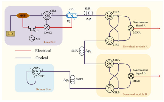
Figure 2.
Scheme of download module in transmission system. LD: laser diode; MOD: modulator; MC: microwave coupler; MS: microwave source; IQMIX: IQ mixer; MIXA, MIXB: mixer; ODL: optical delay line; CIR1, CIR2, CIRA, CIRB: circulators; SMF1, SMF2, SMF3: single-mode optical fiber.
As shown in Figure 2, assume that the microwave source (MS) at the local site outputs a signal with frequency of and phase of , which passes through a microwave coupler (MC) and is divided into two parts. One part is used to modulate the modulator (MOD), while the other serves as the LO port input for the IQMIX. The forward optical signal carrying signal with phase of outputs from the MOD and passes through CIR1, ODL, SMF1, the Download Module A, SMF2, the Download Module B, and SMF3 in turn. Assume that the phase delay of SMF1, SMF2, SMF3 and ODL is , , , and , respectively. The forward optical signal carries a signal whose frequency is and phase is when it reaches the Download Module A. The forward optical signal’s phase is when it reaches the Download Module B. Finally, it reaches the remote site after passing through SMF3 with phase of .
In addition, it serves as the backward optical signal, which is coupled back into SMF3 for transmission. The phase of the backward optical signal is when it reaches the Download Module B. Furthermore, the phase of the backward optical signal is when it reaches Download Module A. Subsequently, the backward optical signal is transmitted back to the local site again with a phase of .
Therefore, the synchronous Signal B can be generated using MIXB to mix the signals carried by the forward and backward optical signal, whose frequency is and phase is
Similarly, the synchronous Signal A can be obtained after being mixed by MIXA with a frequency of and phase of
Based on the above, the frequency synchronous signal can be generated using MIX to mix the signals carried by the forward and backward optical signal, whose frequency is and phase is
Due to differences in the lengths of the fiber pigtails of optical devices, there will be a fixed phase difference between the synchronous signals of different download modules. However, the phase jitter introduced by the fiber pigtails is small, and its impact on the phase stability of the time–frequency-synchronization signal output by the download modules can be neglected.
2.3. Principle of Parallel ODL Control Module
To keep the length of the transmission optical path stable, the phase delay of ODL is constantly controlled so that the phase delay of the transmission optical path . Owing to environmental disturbances, the length of SMF is subject to change, thereby introducing phase jitter . Therefore, the backward optical signal is transmitted back to the local site again with a phase of . As the LO port signal and the backward optical signal share the same frequency, the IQMIX can be used to down-convert the two signals and extract the DC component, thereby obtaining the phase difference between them. And then, the phase delay of the transmission optical path can be obtained. Therefore, the phase jitter can be calculated. To ensure the stability of the transmission optical path, we must adjust the ODL’s phase delay , thereby providing feedback compensation.
The local site ensures the stability of the transmission optical path, thereby ensuring the stability of the time–frequency-synchronization signal’s phase at the download module. However, in practical applications, the large temperature difference in outdoor environments over a day imposes higher requirements on the compensation capability of the ODL. Based on the principle that the phase of the downloaded signal while the phase period is , when the ODL is about to reach the upper limit of its control range, it is moved backward the length of half wavelength (for example, the wavelength of 5 GHz signal is 6 cm) so that the . Thereby achieving continuous control of the transmission optical path length.
However, the resetting process of ODL typically takes a long time, which affects the stability of downloaded signals. Thus, shortening the reset time without compromising the phase stability of downloaded signals becomes a key design focus. We propose a novel parallel ODL control module, where two ODLs are used alternately to achieve continuous smooth control of the transmission optical path. Additionally, an OS is employed to switch between the two parallel ODLs. The schematic diagram of this module is shown in Figure 3. Additionally, it is assumed that the phase delay of the transmission optical path continuously decreases. To maintain the phase stability, the ODL control module needs to increase the phase delay. The control process of the ODL module’s phase delay changing with time is shown in Figure 4.
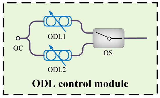
Figure 3.
The scheme of ODL control module.
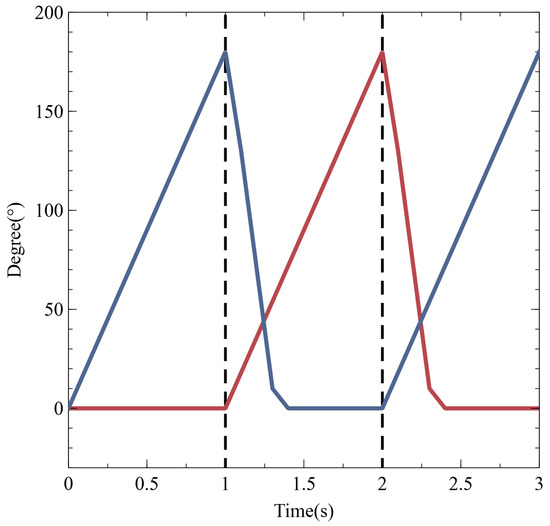
Figure 4.
The control process of the ODL module.
At the initial moment, both ODL1 and ODL2 are moved to the initial point with a phase delay of zero, and their movement range of phase delay is . Assume that the phase delay of ODL1 and ODL2 is and , alternately. The ODL1 is defaulted to control. When ODL1 reaches its maximum range, the OS state is adjusted to select the ODL2 branch. Subsequently, ODL1 is reset to the phase delay of zero, enabling continuous and stable control of the transmission optical path’s phase delay. However, a fixed time is required for the state switching of OS, which limits the system’s ability to further improve the stability of high-frequency signal transmission. Therefore, to minimize the impact of switching time on high-frequency signal transmission, a high-speed OS should be prioritized for use.
3. Experimental Setup
3.1. Experimental Scheme
To verify the feasibility of the current design, a time–frequency-synchronization transmission experiment based on 5 GHz is constructed, and the experimental scheme is shown in Figure 5.
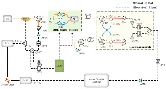
Figure 5.
Scheme of time–frequency-synchronization transmission system. LD: laser diode; MOD: modulator; CIR1, CIR2, CIRA, CIRB: circulator; ODL1, ODL2: optical delay line; OS: optical switch; SMF1, SMF2: single-mode optical fiber; OC, OC1, OC2: optical coupler; BPF1, BPF2, BPF3, BPF4: band pass filter; LPF1, LPF2: low pass filter; AMP1, AMP2, AMP3, AMP4: amplifier; EDFA: erbium-doped fiber amplifier; PD1, PD2: photodetector; IQMIX: IQ mixer; MC: microwave coupler; MS1, MS2: microwave source; MCU: micro control unit.
In our system, the MS1 provides a 5 GHz time–frequency-synchronization signal. It is then split into two paths via MC. One path enters MOD to modulate the optical signal, while the other is connected to the LO port of the IQMIX. Meanwhile, the light from laser diode (LD, optical output power of 10 mW, wavelength of 1550.14 nm) is introduced into MOD (modulation bandwidth of 20 GHz, transmission loss is 7.5 dB) and enters Port 1 of CIR1 and exits Port 2, the output of which is passed as the forward optical signal through transmission optical path, which is composed by ODL control module (consists of two parallel ODLs and OS, length control precision of 0.4134 ), SMF1 (physical length is 16 km) and SMF2 (physical length is 24 km). The optical signal is amplified by EDFA when it passes through Port 2 and Port 3 of CIR2 at the remote site. After amplification, the signal passes through CIR2 from Port 2 again and returns to the transmission optical path, completing the backward optical transmission. When the backward optical signal passes through the transmission optical path, it enters Port 2 of the CIR1 and exits Port 3, returning to the local site again. Then, it passes through the PD1, AMP1, and BPF1 (center frequency of 5 GHz). Finally, it enters the radio frequency (RF) port of IQMIX, where it mixes with the LO port signal. Afterward, the I and Q channel outputs of IQMIX are passes through LPF1 and LPF2 (low pass filter, stop frequency is 50 kHz), and then connected to the analog-to-digital conversion (ADC, 12 bits resolution, with a voltage range of 0–3.3 V) pins of the micro control unit (MCU). Subsequently, the MCU calculates the phase delay of the transmission optical path. Using a PID algorithm, it determines the feedback adjustment required for the ODL control module, thereby ensuring the stability of the phase delay of the transmission optical path.
To verify the stability of the download module, a download module is inserted between SMF1 and SMF2. The forward optical signal enters Port 2 of CIRA and exits Port 3, reaching the download module. The signal is then split into two paths via OC1 (split ratio is 80:20). One of these paths undergoes photoelectric conversion through PD2, signal amplification via AMP2, and filtering through BPF2 (center frequency of 5 GHz and 3-dB bandwidth of 10 MHz). Finally, the signal reaches the LO port of MIX2. The other path enters Port 1 of CIRB and exits Port 2, continuing along the transmission optical path and reaching the remote site. Similarly, the backward optical signal is split into two paths via OC2 (split ratio is 80:20) when it passes through SMF2 and reaches CIRB. One of these paths is detected with PD3, amplified by AMP3, and filtered by BPF3. Subsequently, the signal is connected to the IF port of MIX2. After mixing with the signal at the LO port, it is passed through BPF4 (center frequency of 10 GHz and 3-dB bandwidth of 10 MHz) to extract the upper frequency component, resulting in a time–frequency-synchronization signal with stable frequency and phase. The other path enters Port 1 of CIRA and exits from Port 2, continuing along the transmission optical path until it reaches the local site.
Additionally, to verify the phase stability of the download module signal, another MS2, which is synchronized with a cesium clock and MS1, is used to output a 10 GHz microwave signal. Both the output signal from the download module and the MS2 are connected to the vector network analyzer to observe the phase jitter.
3.2. ODL Control Strategy
3.2.1. System Initialization
Assume that the LO port signal of IQMIX is
where A and f are the amplitude and frequency of the signal. The RF port signal of IQMIX can be expressed as
where B is the amplitude of the signal. After the two signals are mixed in the IQMIX and down-converted, the output signal at Port I is , and the output signal at Port Q is .
After the output values of the I and Q channels are sampled, we need to calculation the phase delay . However, due to the existence of maximum points in the tangent calculation, the cosine calculation is selected to obtain the phase delay , which effectively mitigates interference caused by signal amplitude fluctuations. Then, the delay of ODL is feedback-controlled based on its value within the MCU, thereby ensuring the stability of the system’s transmission phase delay.
By controlling the ODL length from 0–49.2 mm with a step of 0.4134 μm and continuously controlling the sampling voltages of channels I and Q via ADC pins of the MCU, we can obtain the relationship between the phase delay of transmission optical path and the movement length of ODL. The output values of the normalized IQMIX and the calculated cosine results as the ODL moves are presented in Figure 6a.
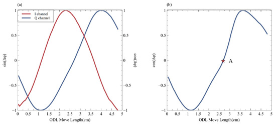
Figure 6.
(a) The output values of the normalized IQMIX with the ODL moving. (b) The calculated cosine results with the ODL moving, and system initial operating point A.
Considering that the slope and direction of the signal curve vary with different ODL move lengths, it is necessary to set an appropriate initial operating point to ensure that the system has sufficient adjustment capability. Therefore, we select the midpoint A as the initial operating point to ensure that the system has optimal adjustment capability, as shown in Figure 6b. However, due to nonlinear errors in the ODL movement process, the cosine value during its operation may exhibit distortion. Nevertheless, the ODL moving direction and step value mainly rely on calculation results in the phase delay control process, so such errors do not affect the subsequent control process.
3.2.2. System Reset
During system operation, the ODL may exceed its adjustable range as the length of the transmission optical path changes continuously. To mitigate this risk, a reset mechanism is designed in the system.
If a single ODL is used, the phase jitter of the downloaded signal from the download module during this process is shown in Figure 7a. The system can complete the reset operation within 22 s and restore the continuous control capability of the phase delay in the transmission optical path. For comparison, the phase jitter of the downloaded signal is shown in Figure 7b using the parallel ODL control module. In this case, the system recovery time is less than 0.5 s. Compared with a single ODL, this module effectively shortens the reset time and achieves stable control of the transmission optical path’s phase delay. However, an instantaneous small phase jitter occurs after optical path switching, and the compensation for this jitter affects the adjustment time of the signal phase in the download module. Such errors can be reduced by fine-tuning the fiber pigtail in subsequent steps.
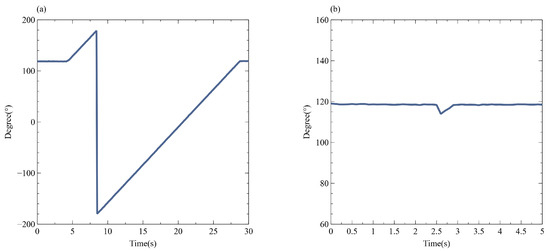
Figure 7.
The phase jitter of the downloaded signal during the system-reset process.
4. Experimental Results
To evaluate the performance of the transmission system, we conducted sequential tests on the frequency stability and phase stability of the output signal from the download module. The experimental results are presented in part Section 4.1, Section 4.2 and Section 4.3.
4.1. Downloaded Signal Frequency Stability Test
To assess the frequency transmission stability of the transmission system, we connected the downloaded signal to a frequency counter. We conduct a 1-h frequency acquisition with control, and results are shown in Figure 8a. Moreover, the results of the Allan Deviation analysis for the frequency data are presented in Figure 8b.
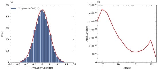
Figure 8.
(a) Frequency changes in downloaded signal within 1 h. (b) The Allan Deviation analysis on the frequency data.
As shown in Figure 8b, the Allan Deviation of the 1-h frequency data from the download module under control is better than . It demonstrates that our system achieves high-stability transmission of the time–frequency-synchronization signal.
4.2. Downloaded Signal Phase Stability Test
To verify the phase stability of the phase of the download signals from the download module, we use a cesium clock as the frequency reference source to synchronize two microwave sources. Among them, the MS1 outputs a 5 GHz microwave signal, which serves as the RF signal input of the transmission system. In contrast, MS2 outputs a 10 GHz microwave signal, which enters Port 1 of the vector network analyzer.
The output signal of the download module is connected to Port 2 of the vector network analyzer, and the vector network analyzer is set to collect 36,000 data points at 3600 s. As shown in Figure 9a, the experimental results demonstrate that the standard deviation of the phase jitter of the downloaded signal is better than 1° when the download signal frequency is 10 GHz.
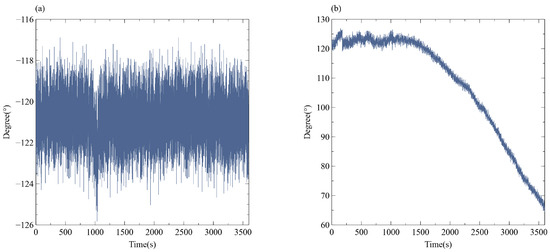
Figure 9.
(a) The phase jitter of the downloaded signal under control within 1 h. (b) The phase jitter of the downloaded signal without control.
Moreover, to fully verify the performance of our system, we conducted a 1 h observation on the phase jitter of the downloaded signal without transmission optical path control again, and the results are shown in Figure 9b. The phase jitter of the downloaded signal from the download module exceeds 60°. Therefore, the synchronization system can control the standard deviation of the transmission optical path phase jitter to within 1°@10 GHz at 1 h, thus maintaining stable long-term operating performance, and effectively overcoming the impacts of environmental disturbances.
4.3. Multiple Downloaded Signals Phase Stability Test
To test the phase stability during simultaneous downloading at multiple locations, we designed a series of experiments. Building on the previous experimental setup, we inserted download modules at arbitrary positions. Specifically, we sequentially inserted Download Module B at the midpoint of SMF1 and another download module C at the midpoint of SMF2. The experimental scheme is shown in Figure 10. The physical length of SMF3, SMF4, SMF5, and SMF6 is 8 km, 8 km, 4 km, and 20 km, respectively. The output signals from these modules are, respectively, connected to multiple ports of the vector network analyzer. We configured the analyzer to collect data points continuously within a specified time frame. By analyzing the collected data, we could precisely evaluate the phase stability of the signals downloaded at various positions.
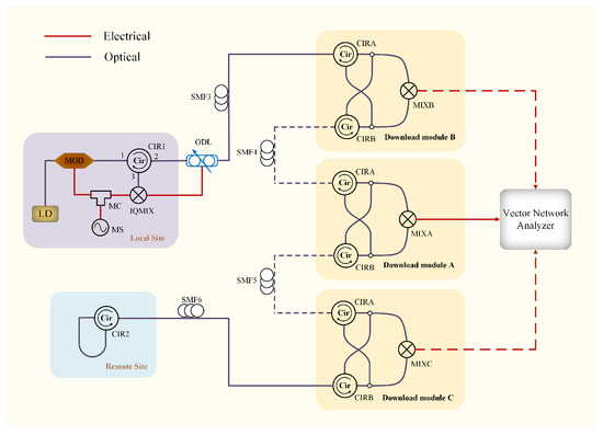
Figure 10.
Experimental scheme for the phase stability test of the multiple-download module.
First, we simultaneously connected the output signals of Download Module A and Download Module B to the vector network analyzer and recorded the changes in the phase jitter within 1 h. The experimental results are shown in Figure 11a. We subsequently enable the Download Module C and repeat the experiment to measure the phase jitter between Download Module A and Download Module C. The experimental results are shown in Figure 11b.
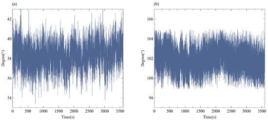
Figure 11.
(a) The phase jitter within 1 h between Download Module A and B. (b) The phase jitter within 1 h between Download Module A and C.
As shown in Figure 11, due to differences in the optical fiber pigtails of each download module, there exists a fixed phase difference among signals downloaded at different nodes. However, the phase jitter can remain stable over the long term, which reflects the performance of the system in maintaining phase stability during multi-location simultaneous downloading. Additionally, the standard deviations of the phase jitter between Download Modules A and B, and between Download Modules A and C, are both less than 1°@10 GHz at 1 h.
5. Comparison and Conclusions
This paper proposes a multi-node downloading scheme for time–frequency- synchronization signals based on phase pre-compensation. The parallel ODL control module proposed in this paper can effectively solve the issue of limited control range and significantly shorten the reset time without relying on the move length of the ODL. In addition, to further ensure the symmetry of the forward and backward optical signal-processing branches in the download module, the signal-download part based on CIR and OC proposed in this paper can effectively ensure the symmetry of optical power in the two signal-processing branches, and thus ensure the stability of the downloaded frequency-synchronization signals.
The experimental results demonstrate that our scheme enables the simultaneous insertion of multiple download modules at arbitrary positions within the transmission optical path. Moreover, the phase jitters among signals downloaded by each download module are stable, effectively achieving synchronization among distributed devices at any position within the transmission optical path. However, a fixed time is required for the state switching of OS, which limits the system’s ability to further improve the stability of high-frequency signal transmission. In the future, how to further optimize the system structure and reduce the impact of OS switching time on the system will be our next research. It is expected to be applied in fields such as aerospace and observational astronomy in the future.
Author Contributions
Conceptualization, J.W. and X.S.; software, X.S.; validation, J.W., X.S., J.Y. and Y.G.; writing—original draft preparation, X.S.; writing—review and editing, J.W., J.Y. and H.L.; supervision, J.W., X.H. and C.H. All authors have read and agreed to the published version of the manuscript.
Funding
This research was supported by the National Natural Science Foundation of China under Grant 62005194.
Institutional Review Board Statement
Not applicable.
Informed Consent Statement
Not applicable.
Data Availability Statement
The data presented in this study are available on request from the corresponding author.
Conflicts of Interest
The authors declare no conflicts of interest.
References
- Takano, T.; Takamoto, M.; Ushijima, I.; Ohmae, N.; Akatsuka, T.; Yamaguchi, A.; Kuroishi, Y.; Munekane, H.; Miyahara, B.; Katori, H. Geopotential measurements with synchronously linked optical lattice clocks. Nat. Photonics 2016, 10, 662–666. [Google Scholar] [CrossRef]
- Foreman, S.M.; Holman, K.W.; Hudson, D.D.; Jones, D.J.; Ye, J. Remote transfer of ultrastable frequency references via fiber networks. Rev. Sci. Instrum. 2007, 78, 021101. [Google Scholar] [CrossRef] [PubMed]
- Cliche, J.F.; Shillue, B. Precision timing control for radioastronomy. maintaining femtosecond synchronization in the atacama large millimeter array. IEEE Control Syst. Mag. 2006, 26, 19–26. [Google Scholar] [CrossRef]
- Caldwell, E.D.; Sinclair, L.C.; Newbury, N.R.; Deschenes, J.D. The time-programmable frequency comb and its use in quantum-limited ranging. Nature 2022, 610, 667–673. [Google Scholar] [CrossRef] [PubMed]
- Xin, M.; Afak, K.; Krtner, F.X. Ultra-precise timing and synchronization for large-scale scientific instruments. Optica 2018, 5, 1564. [Google Scholar] [CrossRef]
- Williams, P.A.; Swann, W.C.; Newbury, N.R. High-stability transfer of an optical frequency over long fiber-optic links. J. Opt. Soc. Am. B 2008, 25, 1284–1293. [Google Scholar] [CrossRef]
- Fujieda, M.; Kumagai, M.; Gotoh, T.; Hosokawa, M. First experiment of ultra-stable frequency transfer system via optical fiber in NICT. In Proceedings of the 2007 IEEE International Frequency Control Symposium Joint with the 21st European Frequency and Time Forum, Geneva, Switzerland, 29 May–1 June 2007; pp. 840–844. [Google Scholar] [CrossRef]
- MacPherson, W.N.; Rigg, E.J.; Jones, J.D.; Kumar, V.R.K.; Knight, J.C.; Russell, P.S.J. Finite-element analysis and experimental results for a microstructured fiber with enhanced hydrostatic pressure sensitivity. Light. Technol. J. 2005, 23, 1227–1231. [Google Scholar] [CrossRef]
- Liu, C.; Jiang, T.; Wang, H.; Lei, M.; Liu, T.; Yu, S. Phase-Modulation-Based Stable Radio Frequency Transmission via 125 km Fiber Optic Link. Photonics J. IEEE 2023, 15, 5. [Google Scholar] [CrossRef]
- Zang, Q.; Quan, H.; Zhao, K.; Zhang, X.; Deng, X.; Xue, W.; Chen, F.; Liu, T.; Dong, R.; Zhang, S. High-Precision Time-Frequency Signal Simultaneous Transfer System via a WDM-Based Fiber Link. Photonics 2021, 8, 325. [Google Scholar] [CrossRef]
- Liu, L.; Cheng, N.; Wang, J.; Tong, Z.; Cao, Q.; Ying, K.; Gui, Y. Stable optical and radio frequency joint transfer based on a passive phase compensation. Opt. Express 2022, 30, 45980–45987. [Google Scholar] [CrossRef] [PubMed]
- Hu, C.; Luo, B.; Pan, W.; Yan, L.; Zou, X. Multipoint stable radio frequency long distance transmission over fiber based on tree topology, with user fairness and deployment flexibility. Opt. Express 2020, 28, 23874–23880. [Google Scholar] [CrossRef] [PubMed]
- Wang, X.; Wei, W.; Weng, X.; Wang, D.; Wei, J.; Xie, W.; Dong, Y. Elimination of the PMD related delay jitter in a fiber stretcher based ultra-stable microwave signal distribution system. Opt. Express 2021, 29, 41609–41621. [Google Scholar] [CrossRef]
- Wang, X.; Wei, W.; Ye, B.; Xie, W.; Tan, Z.; Dong, Y. Ultra-stable wideband signal dissemination for distributed systems. J. Light. Technol. 2023, 41, 7177–7182. [Google Scholar] [CrossRef]
- Chen, Z.; Zhou, T.; Zhong, X.; Liu, J.; Wang, M.; Ye, J. Stable downlinks for wideband radio frequencies in distributed noncooperative system. J. Light. Technol. 2018, 36, 4514–4518. [Google Scholar] [CrossRef]
- Zhang, H. Performance Investigation of Wideband Microwave Frequency Fiber-Optic Multi-Access in Harsh Ambient Environment. IEEE Photonics J. 2023, 15, 5501706. [Google Scholar] [CrossRef]
- Jin, Z.; Chen, Z.; Wu, K.; Yu, D.; Wu, G.; Yu, S.; Luo, B.; Guo, H. Node-downloadable frequency transfer system based on a mode-locked laser with over 100 km of fiber. Opt. Express 2023, 31, 39681–39694. [Google Scholar] [CrossRef] [PubMed]
- Jiang, Z.; Dai, Y.; Zhang, A.; Yin, F.; Li, J.; Xu, K.; Lv, Q.; Ren, T.; Tang, G. Precise Time Delay Sensing and Stable Frequency Dissemination on Arbitrary Intermediate Point Along Fiber-Optic Loop Link With RF Phase Locking Assistance. IEEE Photonics J. 2017, 7, 7200809. [Google Scholar] [CrossRef]
Disclaimer/Publisher’s Note: The statements, opinions and data contained in all publications are solely those of the individual author(s) and contributor(s) and not of MDPI and/or the editor(s). MDPI and/or the editor(s) disclaim responsibility for any injury to people or property resulting from any ideas, methods, instructions or products referred to in the content. |
© 2025 by the authors. Licensee MDPI, Basel, Switzerland. This article is an open access article distributed under the terms and conditions of the Creative Commons Attribution (CC BY) license (https://creativecommons.org/licenses/by/4.0/).