Article

Research on Networking Protocols for Large-Scale Mobile Ultraviolet Communication Networks

College of Communication Engineering, Army Engineering University of PLA, Nanjing 210007, China
*
Author to whom correspondence should be addressed.
Photonics 2025, 12(7), 710; https://doi.org/10.3390/photonics12070710
Submission received: 26 May 2025 / Revised: 1 July 2025 / Accepted: 11 July 2025 / Published: 14 July 2025
(This article belongs to the Special Issue Free-Space Optical Communication and Networking Technology)

Abstract

Ultraviolet (UV) communication, characterized by non-line-of-sight (NLOS) scattering, holds substantial potential for enabling communication networking in unmanned aerial vehicle (UAV) formations within strong electromagnetic interference environments. This paper proposes a networking protocol for large-scale mobile ultraviolet communication networks (LSM-UVCN). In large-scale networks, the proposed protocol establishes multiple non-interfering transmission paths based on a connection matrix simultaneously, ensuring reliable space division multiplexing (SDM) and optimizing the utilization of network channel resources. To address frequent network topology changes in mobile scenarios, the protocol employs periodic maintenance of the connection matrix, significantly reducing the adverse impacts of node mobility on network performance. Simulation results demonstrate that the proposed protocol achieves superior performance in large-scale mobile UV communication networks. By dynamically adjusting the connection matrix update frequency, it adapts to varying node mobility intensities, effectively minimizing control overhead and data loss rates while enhancing network throughput. This work underscores the protocol’s adaptability to dynamic network environments, providing a robust solution for high-reliability communication requirements in complex electromagnetic scenarios, particularly for UAV swarm applications. The integration of SDM and adaptive matrix maintenance highlights its scalability and efficiency, positioning it as a viable technology for next-generation wireless communication systems in challenging operational conditions.

1. Introduction

Ultraviolet (UV) communication is a type of wireless optical communication that uses ultraviolet light with a shorter wavelength as the communication carrier. During the propagation process, it is highly prone to scattering, enabling non-line-of-sight (NLOS) communication. Compared with traditional atmospheric laser communication, UV communication eliminates the complex aiming, pointing, and tracking systems, and is more suitable for small and micro platforms such as drones that have high requirements for link alignment but limited load capacity. Due to its characteristic of being easily scattered, the path loss of UV light during propagation in the atmosphere is relatively high, which limits the communication rate and distance of point-to-point UV communication, usually within a range of 100–200 m, and the rate ranges from several tens of Kbps to one hundred Mbps [1,2,3,4,5,6,7]. Combining UV communication with self-organizing networks and constructing UV self-organizing networks can effectively overcome this problem. In recent years, swarm drones have developed rapidly in military, civil, and other applications. With the characteristics of NLOS communication, high confidentiality, and strong anti-interference ability, UV communication has great development potential in solving communication problems of drone swarms in strong electromagnetic interference environments.
In the application of drone group networking, traditional radio frequency communication can easily ensure that any two nodes in the network can directly communicate without relaying or through one or two relays by taking advantage of its communication rate and distance, and improve the network performance through complex protocols. However, when applied to the same scenarios, due to the limitations of communication rate and distance, UV communication networks have to adopt networking protocols with lower complexity. Moreover, communication between nodes may rely on more relays, which not only leads to a decrease in throughput but also increases the probability of data interference during the transmission process. This poses more stringent requirements for the networking protocols applied to UV communication networks.
Refs. [8,9] have designed a directional MAC protocol for flight formations. This protocol can enhance network throughput and reduce latency through means such as channel reservation. However, this protocol is designed for large platforms. Without the constraints of energy supply and load, the communication distance and rate can be significantly increased by adding light sources, boosting optical power, and other measures, so it is not applicable to small and micro platforms like drones. Refs. [10,11] have proposed clustering-based UV communication network protocols. In the proposed protocols, nodes with a large spacing are divided into different clusters. The cluster heads are responsible for the management of nodes within the clusters and the allocation of channels, thereby achieving spatial division multiplexing among different clusters. Although the network scale can be expanded by increasing the number of clusters and cluster members, a large number of cluster members are only gathered around the cluster heads, resulting in the fact that the actual coverage area of the network is difficult to effectively expand. In addition, such clustering-based protocols have a high degree of dependence on high-performance cluster heads, which leads to a decrease in the reliability of the protocol and a significant increase in complexity. Refs. [12,13,14] implements time division multiple access (TDMA) by allocating channels to nodes, which avoids channel competition and can significantly improve channel utilization. Refs. [15,16,17,18] proposed and refined a MAC protocol that enables competition-free communication in multi-hop networks, eliminating resource wastage caused by competition. The protocol also introduces a bit-by-bit forwarding-based relay mechanism, ensuring data transmission from the source node to the destination node within each time slot. Leveraging the competition-free mechanism, ref. [19] has developed an innovative neighbor discovery algorithm based on the time difference of arrival. The proposed protocol, utilizing the neighbor table, enables efficient shortest path selection throughout the network. This not only minimizes the overall energy consumption but also substantially boosts the data throughput. By striking an optimal balance between energy efficiency and transmission performance, the protocol significantly enhances the network’s operational effectiveness and reliability. The aforementioned protocols predominantly focus on small-scale network scenarios, demonstrating satisfactory functionality and reliability within such application environments. However, when applied to large-scale networks, these protocols fail to adequately account for the dynamic growth characteristics of channel resources engendered by network expansion. In particular, in large-scale network environments, the substantial increase in the number of nodes not only significantly elevates the complexity of channel resource allocation and management but also exacerbates the cumulative interference among nodes, which can severely degrade network performance. Evidently, there remains considerable room for enhancing the scalability and adaptability of these protocols in large-scale network scenarios.
Furthermore, the performance evaluation and design optimization of existing UV communication network protocols mainly center around static network scenarios, lacking a systematic consideration of mobile network environments. In the practical application of drone group networking, the operational state of the network is influenced by multiple factors such as meteorological conditions and mission requirements, and the spatial positions of drone nodes exhibit a high degree of dynamics and uncertainty. Given the inherent characteristics of limited communication distance and easy signal scattering in UV light communication, changes in the spatial positions of nodes may lead to the interruption of communication links or interference between nodes, thus causing frequent changes in the network topology. In long-distance communication scenarios, data transmission highly relies on multi-level relay forwarding by intermediate nodes. At this time, any change in the position of nodes on the transmission path may result in transmission interference or physical disconnection of communication links, posing significant challenges to the overall communication performance of the network. Therefore, conducting in-depth research on the key parameters affecting network performance in extreme environments and designing dynamic response mechanisms that are both efficient and reliable are essential research steps for constructing a flexible networking protocol system and verifying the practicality of the protocols.
In summary, the core considerations in designing a networking protocol for large-scale mobile UV communication networks lie in the following: overcoming the impact of low communication rates and multiple relaying on throughput in UV communication; reasonably allocating channel resources to improve resource utilization; and mitigating the adverse effects of mobile scenarios on network performance. We have designed a networking protocol applicable to large-scale mobile UV communication networks (LSM-UVCN). The main features of this protocol are as follows:
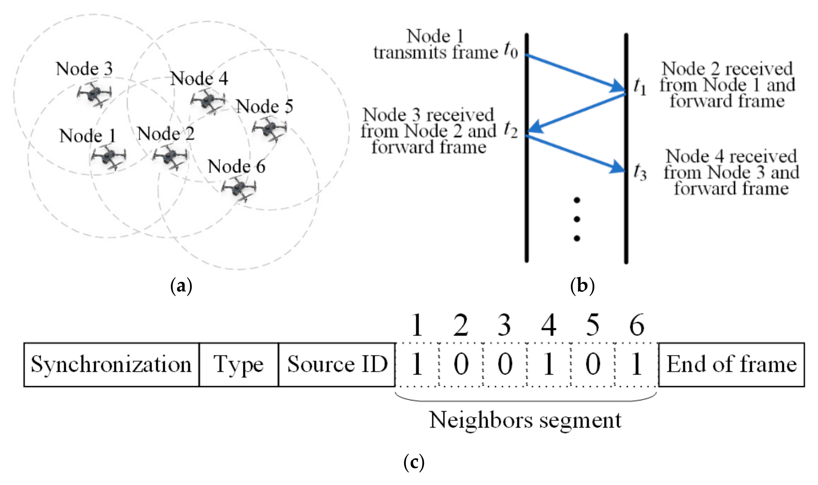
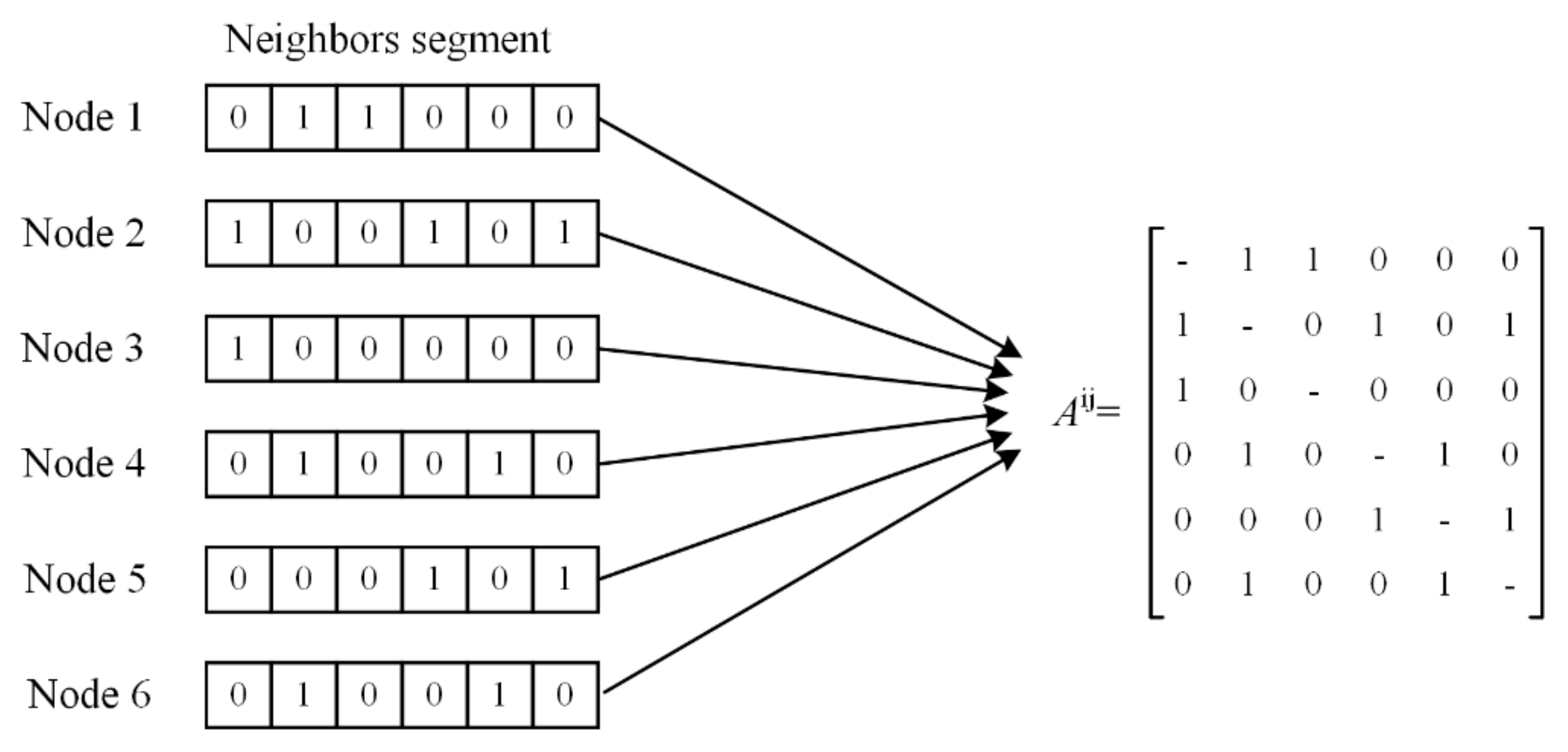
  • In view of the bandwidth limitation of UV communication, a novel neighbor discovery algorithm is designed based on a lossless competition mechanism. The proposed neighbor discovery algorithm can generate a network connection matrix with extremely low control overhead, which covers the connection relationships of all nodes in the network.
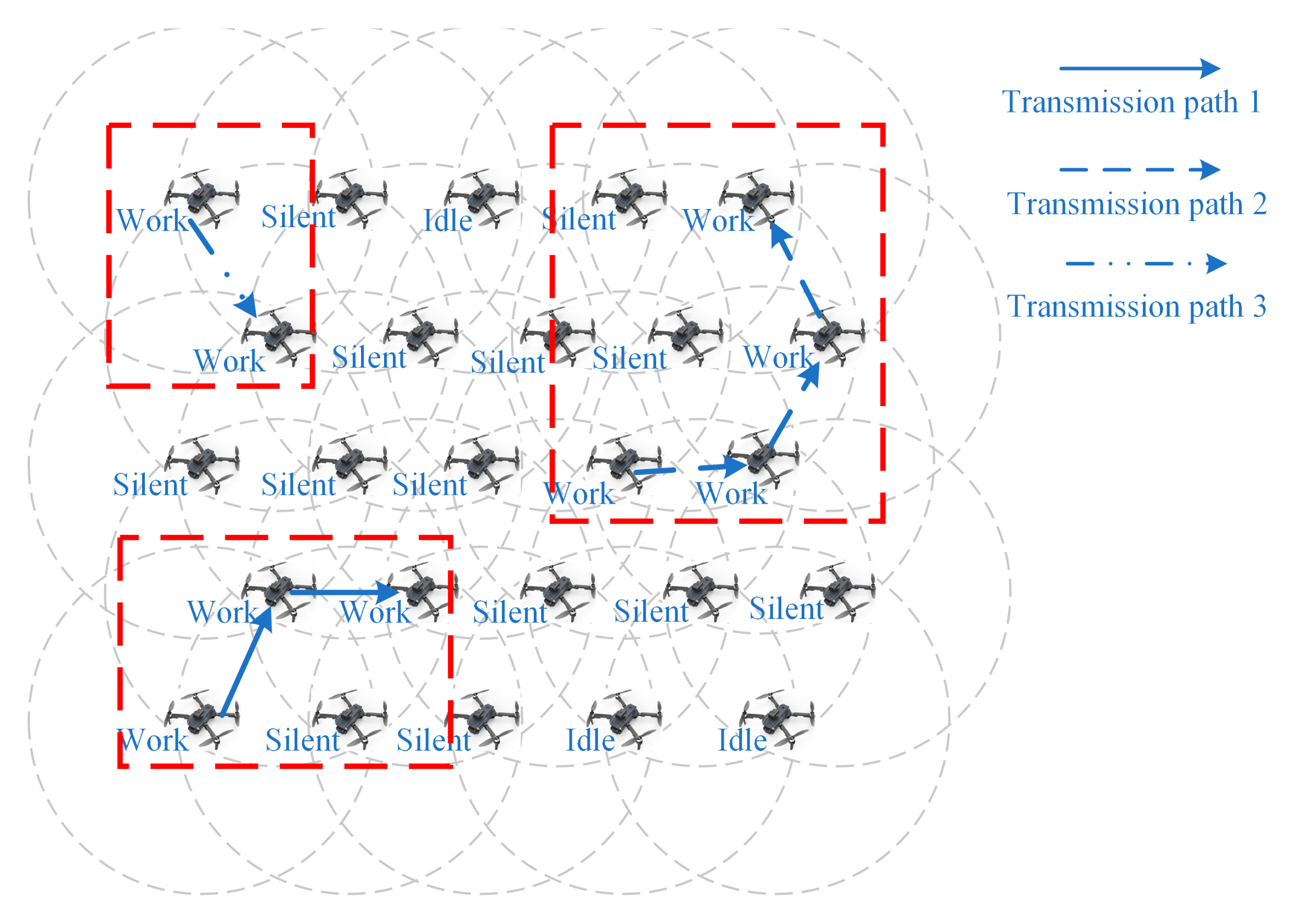
  • A channel access mechanism of “competition-first-then-transmission” is designed. Based on the network connection matrix, the protocol establishes multiple transmission paths synchronously through multi-round competition, and prevents interference between adjacent transmission paths by setting interference isolation nodes, so as to realize spatial division multiplexing and further alleviate the problem of low throughput in ultraviolet communication networks.
  • To address the issue of random changes in network topology in mobile networks, the proposed protocol, based on a neighbor discovery algorithm with low control overhead, can effectively reduce the adverse impact of frequent network topology changes on network performance by periodically updating the connection matrix.
The subsequent chapters of this article are organized as follows: In Section 2, the proposed neighbor discovery algorithm, networking protocol, and mobility model are introduced in detail. Section 3 conducts an analysis of the key parameters influencing network performance and derives the calculation formulas for throughput and data loss rate. In Section 4, the Monte Carlo method is employed to perform simulation analyses of network performance under different parameter settings and motion conditions. Finally, Section 5 summarizes the entire article and discusses the directions for future research and development.

2. LSM-UVCN

LSM-UVCN is a strictly time-slot synchronized communication protocol. Nodes within the network adopt an omnidirectional communication mode and the on–off keying (OOK) modulation scheme, where light emission and non-emission are used to represent transmitted bits “1” and “0”, respectively. When a node initiates data transmission, the remaining nodes implement a bit-by-bit forwarding relay mechanism. This mechanism ensures that all nodes in the network receive the identical bit signal from the source node at precisely the same moment.

2.1. Neighbor Discovery Algorithm

Owing to the low data rate of UV communication, the designed neighbor discovery algorithm should aim to minimize control overhead, thereby preventing excessive control overhead from impairing effective data transmission.
The proposed neighbor discovery algorithm consists of two processes: distance determination and neighbor broadcasting. In these two processes, nodes transmit two types of control frames respectively. The first-type control frame consists of only a synchronization field (8 bits), a frame type field (2 bits), a source node ID field (8 bits), and a frame end field (8 bits), with a length of 26 bits. In addition to the above fields, the second-type control frame includes a neighbor node field (n bits, where n is the total number of nodes in the network), with a length of 26 + n bits. The proposed protocol employs a lossless competition mechanism, which can ensure the successful transmission of one control frame per time slot, avoiding channel resource waste caused by channel competition. The information payload required for the network to complete one neighbor discovery is 2n bits. In a 100-node network, when the point-to-point communication rate is 10 Mbps and the number of relays required for communication between the farthest nodes in the network is 20, the time required for the network to complete one neighbor discovery is approximately 0.3 ms.
In the distance determination phase, a node broadcasts a first-type control frame across the entire network. Upon receiving the distance determination frame, a node utilizes the time difference of arrival algorithm to identify neighbor nodes within a one-hop range. Subsequently, it generates a neighbor broadcast frame, as illustrated in Figure 1.
Figure 1a presents an example of a network topology with six nodes. Assume that the maximum communication distance of a node is d, and the propagation speed of ultraviolet light in the atmosphere is c. Node 1 starts to transmit the first type of control frame at time t0. After other nodes receive the control frame, they determine the distance from the source node to their own node based on the time difference Δt between the moment when they first receive the signal and the starting moment t0 of the time slot. For instance, Node 2 receives the signal at time t1, and at this time, Δt = (t1t0). Since Δt × cd, Node 2 can confirm that the received signal is directly transmitted by the source node, and Node 1 is a neighbor within its one-hop range. Similarly, for other nodes such as Node 2 and Node 3, when they receive the signal, Δt × c > d. From this, it can be determined that the received signal is forwarded by a relay node, and the source node is beyond its one-hop range, as shown in Figure 1b.
Nodes continuously determine the distance between the source node and themselves based on the distance determination frames transmitted by other nodes, and generate the second type of control frames. The second type of control frames mainly consists of three parts. The “head of frame” contains fields such as the frame type and the ID of the node itself, and the “end of frame” contains the frame end field. The “neighbors segment” serves as the core of the second type of control frame. Each of the six bits in it respectively indicates the connection relationships between the node itself and other nodes in the network. If a corresponding node is reachable within one hop from the node itself, the corresponding bit is set to “1”; otherwise, it is set to “0”. As shown in Figure 1c, for the second type of control frame generated by Node 2, its neighbor nodes within one hop are Node 1, Node 4, and Node 6. Therefore, the first, third, and sixth bits of its “neighbors segment” are “1”, and the remaining bits are “0”.
After the distance determination is completed, the neighbor discovery process enters the neighbor broadcasting process. Each node broadcasts the generated second type of control frame to the network. By collecting the neighbor broadcast frames of other nodes, a network connection matrix is generated, as shown in Figure 2.
The connection matrix comprehensively encapsulates the inter-nodal connectivity relationships throughout the network infrastructure. Specifically, when the element Aij within the matrix assumes a value of “1”, it denotes that nodes i and j are mutually situated within a one-hop communication range. Through systematic traversal of this matrix, any node is empowered to enumerate all viable data transmission routes between arbitrary pairs of nodes. Upon obtaining the identifiers of the source and destination nodes, a node can utilize a unified routing algorithm to ascertain the requisite relay nodes for data conveyance, as well as those nodes along the transmission path that may induce interference. This process enables the node to accurately discern the available channel resources that remain unencumbered. Moreover, the proposed protocol uses “0” and “1” to denote the connectivity status between nodes. In a 100-node network, each node can establish the connection matrix by constructing 100 registers with 100 bits each, thus significantly reducing both computational complexity and storage difficulty.
It is imperative to note that the connection matrix established via the neighbor discovery algorithm merely represents a snapshot of the network topology at a given instant. As nodes undergo mobility, the dynamic alterations in inter-nodal connectivity render the existing matrix obsolete. The rate of matrix obsolescence is directly proportional to the velocity of nodal movement. Hence, during the course of data transmission, periodic execution of neighbor discovery procedures is indispensable to maintain an up-to-date and accurate representation of the network connection matrix.

2.2. Networking Protocol

Protocols based on competition-free mechanisms can ensure the normal transmission of the highest-priority data during channel competition, adhering to the “one frame per time slot” principle even under intense competition [15,16,17,18,19,20]. This approach significantly enhances channel utilization while preserving network flexibility. However, in large-scale network scenarios with exponentially increasing channel resources, such protocols remain constrained to transmitting a single frame per time slot. This limitation prevents performance scaling with resource expansion and may even degrade efficiency due to increased inter-node distances.
Through in-depth analysis, we identified that competition-free protocols require full network connectivity, necessitating the broadcast of data to all nodes. Nevertheless, only the competition segment (priority segment) of the frame is critical for achieving competition-free transmission. Once this segment is transmitted and the winning node is determined, other nodes cease transmission. Hence, the root cause of channel resource wastage lies in the continued broadcast of subsequent frame segments across the network after competition resolution.
LSM-UVCN addresses this inefficiency by decoupling channel competition from data transmission. It establishes multiple non-interfering data transmission paths through successive competition rounds, followed by simultaneous data transmission from multiple source nodes to achieve spatial division multiplexing, as illustrated in Figure 3.
First, the network enters the neighbor discovery stage, during which a connection matrix is established in each node. Subsequently, the network proceeds to the transmission stage, which comprises multiple complete transmission cycles. Each complete transmission cycle includes several channel competition time slots and one data transmission time slot.
In the channel competition time slots, nodes engage in competition-free competition with other nodes by broadcasting short frames that contain only the source node ID, destination node ID, and priority field. Eventually, the node with the highest priority successfully wins the competition. Then, a transmission path is established by traversing the connection matrix.
The proposed protocol employs a shortest path selection algorithm prioritizing high-priority nodes to establish transmission paths. Taking the network topology shown in Figure 1a as an example, when Node 3 needs to transmit data to Node 1 and successfully wins the competition, each node uses Node 3 as the source and generates a hop-by-hop neighbor table by traversing the connection matrix, as shown in Figure 4. Subsequently, each node determines a unique transmission path in Figure 4 according to the strategy of selecting the shortest path via high-priority nodes, thereby completing path establishment.
During the data transmission time slot, instead of broadcasting data across the entire network, only the relay nodes on the transmission path perform relay forwarding. Through simultaneous data transmission along multiple transmission paths, SDM can be achieved, enabling the full utilization of channel resources and enhancing network performance.

2.3. Node State Transition

To ensure the establishment of multiple transmission paths and the mutual isolation between these paths, the protocol classifies nodes into three states: Idle, Silent, and Work.
Nodes in the Idle state represent unoccupied nodes, and all nodes are initially in the Idle state. The Work state indicates that the node is occupied by a transmission path. Nodes in the Silent state are primarily tasked with isolating different transmission paths during the data transmission time slot to prevent mutual interference.
During the channel competition phase, nodes applying for channel competition need to meet three requirements:
  • The node is in the Idle state.
  • The node has data to transmit.
  • There is an available transmission path between the node and the destination node.
Whenever a node wins the channel competition, by traversing the connection matrix and employing a routing algorithm that gives priority to high-priority nodes, the transmission path between the source node and the destination node is determined accordingly. At this time, the state of all nodes on the transmission path changes from the Idle state to the Work state, and other Idle nodes within one hop of the nodes in the Work state change to the Silent state.
After each channel competition, nodes promptly modify the states of various nodes in the connection matrix. Nodes that have changed to the Work state cannot be occupied by subsequently generated transmission paths. Nodes that have changed to the Silent state also cannot be selected as Work nodes by subsequently generated transmission paths, but the same Silent nodes can be multiplexed by multiple different paths. After the state transition is completed, nodes that still meet the competition conditions will continue to compete for the channel in the next competition time slot.
Through multiple consecutive competitions, the nodes in the network are successfully divided into multiple transmission paths. When no nodes continue to compete for the channel, the network enters the data transmission stage. At this time, all nodes that have won the competition start to transmit data simultaneously. The duration of the data transmission stage is a constant Tdata, and each source node dynamically adjusts the payload to be transmitted Bdata according to the number of hops m required to reach the destination node, with Bdata = T/m bits.
During the data transmission stage, only nodes in the Work state will transmit or forward data, while nodes in the Idle and Silent states remain silent throughout and do not forward any data. Through the “isolation zone” set by the Silent nodes, each transmission path can avoid mutual interference, achieving SDM. After the data transmission is completed, all nodes return to the Idle state and enter the next complete transmission cycle.
Figure 5 depicts a 5 × 5 network. Through three rounds of channel competition, three transmission paths are successively generated. Different paths do not reuse nodes in the work state, and they are separated from each other by nodes in the silent state, effectively preventing interference between links. At the start of data transmission, three source nodes initiate data transmission simultaneously. In Transmission Path 1, the distance between the source node and the destination node is two hops, so the actual amount of data that can be transmitted is (Tdata/2) bits. Similarly, the amounts of data that can be transmitted in Transmission Paths 2 and 3 are (Tdata/3) bits and Tdata bits, respectively. After the data transmission is completed, all nodes return to the Idle state, and a new round of competition commences.
The protocol relies on the established connection matrix. Through multiple rounds of competition and the isolation provided by silent nodes, it can fully utilize the increased channel resources in a large-scale network, significantly enhancing network performance. However, the non-interfering transmission paths established based on the expired connection matrix may experience path breaks or cross-interference in practical scenarios, leading to a decline in network performance. Therefore, the protocol requires periodic updates to the connection matrix to mitigate the adverse impact of node mobility on network performance.

3. Network Performance Analysis

3.1. Basic Parameters

The commonly used parameters in the analysis are shown in Table 1.

3.2. Network Performance

LSM-UVCN relies on the connection matrix to achieve SDM. Frequent changes in the network topology can render the connection matrix no longer representative of the actual network topology, leading to transmission failures. The main impacts are as follows:
  • As nodes move, the communicable links in the connection matrix may be disrupted, causing nodes to establish incorrect transmission paths.
  • The non-interfering transmission paths established through multiple rounds of competition based on the connection matrix may cross due to node mobility. Interference may occur during the data transmission process, resulting in transmission failures.
  • During the neighbor discovery process, nodes may experience transmission failures of neighbor discovery control frames due to errors such as bit errors. This can lead to the establishment of incorrect connection matrices in the nodes, preventing the nodes from functioning properly during subsequent data transmission cycles.

3.2.1. Path Break

Assume that within the channel competition phase of LSM-UVCN, the average number of relaying operations for the established transmission paths is denoted as m. This numerical value implies that each transmission path comprises a total of (m + 2) nodes interconnected by m point-to-point communication links. During the Transmission stage, the integrity of the entire transmission path is critically contingent upon the connectivity of all its constituent links. Specifically, the disruption of even one single link among these m links, triggered by nodal mobility, will inevitably lead to the breakdown of the entire transmission path.
Furthermore, the relative displacement distance r between any two nodes over a given time interval t adheres to a Rayleigh distribution. The probability density function that characterizes this statistical behavior is given as Equation (1).
f ( r , t ) = r ( v rel t ) 2 exp ( r 2 2 ( v rel t ) 2 ) .
Let the initial distance between adjacent nodes be d0. Then, when r > Ad0, the link is broken. The probability of link breakage can be obtained as Equation (2):
P link _ break = A f ( r , t ) d r = exp ( A 2 2 ( v rel t ) 2 ) .
Furthermore, in two-dimensional random motion, the relative moving speed of any two nodes is vrel, with vrel = 2 v. The probability that the transmission path remains connected during the data transmission phase can be expressed by Equation (3):
P path _ alive = ( 1 P link _ break ) m = 1 exp ( A 2 4 v 2 t 2 ) m ,   t ( 0 , T ref ) .

3.2.2. Inter-Path Interference

During the data transmission process, different transmission paths avoid mutual interference through the “isolation zone” formed by the silent nodes. However, due to the random movement of nodes, when the work nodes originating from different transmission paths become adjacent again, mutual interference is bound to occur, resulting in the failure of data transmission.
In each transmission path, the total number of nodes in the work state is m + 1. Consequently, the total number of nodes in the work state across M transmission paths is M(m + 1).
Interference only occurs between pairs of nodes in the work state from different paths. The total number of node pairs can be determined by Equation (4):
C ( S , 2 ) = S ( S 1 ) 2 S 2 2 .
Since the two nodes in the node pair belong to different transmission paths, with d0 > A. With the movement of the nodes, interference occurs when d0rA.
P interfere , pair ( d 0 ) = d 0 f ( r ) d r = exp ( ( d A ) 2 4 v 2 t 2 ) A 2 v t ,     v t A .
By means of the approximation of the small probability event, the probability of no interference can be obtained.
P no _ interfere = ( 1 P interfere , pair ) C ( S , 2 ) 1 n 2 A 4 v t .

3.2.3. Errors in Neighbor Discovery

LSM-UVCN is highly dependent on the connection matrix. If there are bit errors during the transmission of neighbor discovery control frames in the process of neighbor discovery in the network, nodes will generate incorrect connection matrices as a result. This will prevent the node from establishing a correct transmission path until the next neighbor discovery.
Given that the total frame length of the neighbor discovery control frame is Bctrl, a node can only establish a correct connection matrix if it receives all control frames sent by the (n − 1) other nodes without any bit errors. The probability Psingle that a single node successfully establishes the connection matrix is Psingle.
P single = ( 1 B E R ) ( n 1 ) B ctrl .
Noccupied denotes the total number of nodes occupied by a single transmission path. The nodes occupied by a transmission path include not only those in the Work state but also all Silent nodes within one hop of any Work node. Given that the average number of neighbors within one hop for each node is πρA2. In a single transmission path, the probability that all nodes successfully establish a connection matrix is Pmatrix.
N occupied = ( m + 1 ) + 2 ( π ρ A 2 1 ) + ( m 1 ) ( π ρ A 2 2 ) P matrix = ( 1 B E R ) ( n 1 ) N occupied B ctrl .

3.2.4. Bit Errors

In this protocol, the data transmission time is a fixed value Tdata, based on which the probability of error-free data transmission can be calculated.
P no _ ber = ( 1 B E R ) T data / T clk .

3.2.5. Throughput and Data Loss Rate

By combining Equations (3), (6), (8) and (9), the probability Ploss of data transmission failure and data loss can be obtained.
P success = P path _ alive P no _ interfere P matrix P no _ ber P loss = 1 P success = 1 1 exp ( A 2 4 v 2 t 2 ) m ( 1 n 2 A 4 v t ) ( 1 B E R ) ( n 1 ) h N occupied B ctrl
The average throughput of the network can be jointly represented by the number Npath of transmission paths established in an average complete transmission cycle and the average data volume Bpath per transmission path.
T h r o u g h p u t = B path T data · N path
Only when the established transmission path does not experience interference, bit errors, or breakage during Tdata is the data transmission valid. Therefore, when a single path successfully transmits data, the data volume it carries can be calculated.
B p a t h = T data m T clk · P s u c c e s s
In the limiting case where none of the transmission paths occupy Silent nodes, it follows that
N path = n N occupied = n ( m + 1 ) ( c 1 ) + 2 n m + 1
By combining the above equations, the final expression for the average throughput of the network can be obtained as follows:
T h r o u g h p u t = n ( m + 1 ) m T clk 1 exp ( A 2 4 v 2 t 2 ) m ( 1 n 2 A 4 v t ) ( 1 B E R ) ( n 1 ) T data N occupied B ctrl T clk
As indicated in Equation (14), the fewer nodes occupied by each average transmission path, the more transmission paths the network can establish simultaneously, and the higher the throughput. The protocol employs a shortest path selection algorithm with high-priority nodes taking precedence, which can significantly reduce the number of nodes occupied by established transmission paths.
Additionally, the impact of node density on network performance is also of great importance. On one hand, a higher node density results in fewer hops required for transmission paths, allowing nodes to transmit more data within Tdata. Moreover, the network exhibits a higher connectivity probability, avoiding data loss caused by the destination node not being in the same subnet. However, the number of silent nodes occupied by transmission paths also increases with higher node density, reducing the number of simultaneously establishable paths. On the other hand, when the node density is low, the network is likely to be partitioned into multiple subnets with high probability, degrading network performance.
In mobile networks, mobility speed is one of the most critical influencing factors. An increase in node mobility speed accelerates changes in network topology, triggering issues such as interference, link breakage, or matrix expiration, which degrade network performance. Furthermore, in networks with low node density, node mobility further increases the probability of interference between different paths. When the mobility speed is high, shortening the neighbor discovery cycle and updating the connection matrix in a timely manner can mitigate the adverse effects of node mobility on network performance.

4. Simulations

4.1. Mobility Model

In practical engineering applications, the motion states of UAV nodes exhibit significant dynamic characteristics due to the coupling effects of multiple factors such as mission planning, time scheduling, and meteorological conditions. Particularly in extremely harsh weather environments, the trajectories of UAVs can be approximated using a Brownian motion model.
For theoretical analysis and simulation verification, this paper abstracts the relative displacement of UAV nodes into a two-dimensional planar random motion model. Within a square area of side length L, starting from the initial time t0, each node randomly selects a direction of motion within the range [0, 2π] and moves in a straight line at a constant velocity v. Every t seconds, the node reselects its direction while maintaining the same speed. If the node predicts that its trajectory will exceed the boundary of the predefined area after t seconds, a direction reselection mechanism is immediately triggered.
This random mobility model introduces high unpredictability and disorder into node trajectories. As the velocity v increases, the dynamic variation of the network topology grows nonlinearly. LSM-UVCN relies heavily on the neighbor table constructed by the neighbor discovery algorithm. Under the aforementioned random mobility model, frequent node movements cause the connection matrix to quickly become outdated, making it difficult to accurately reflect the real-time network topology. When nodes plan transmission paths based on outdated neighbor tables, the success rate of data transmission decreases significantly, leading to a severe degradation of overall network performance. Therefore, to mitigate the negative impact of node mobility on network performance, efficient dynamic updates of the connection matrix are essential to maintain the stability and reliability of the protocol.

4.2. Basic Parameters

This paper uses Omnet++ to simulate the network performance when nodes move randomly, and the initial network topology is a 10 × 10 square node matrix. The key simulation parameters are shown in Table 2.

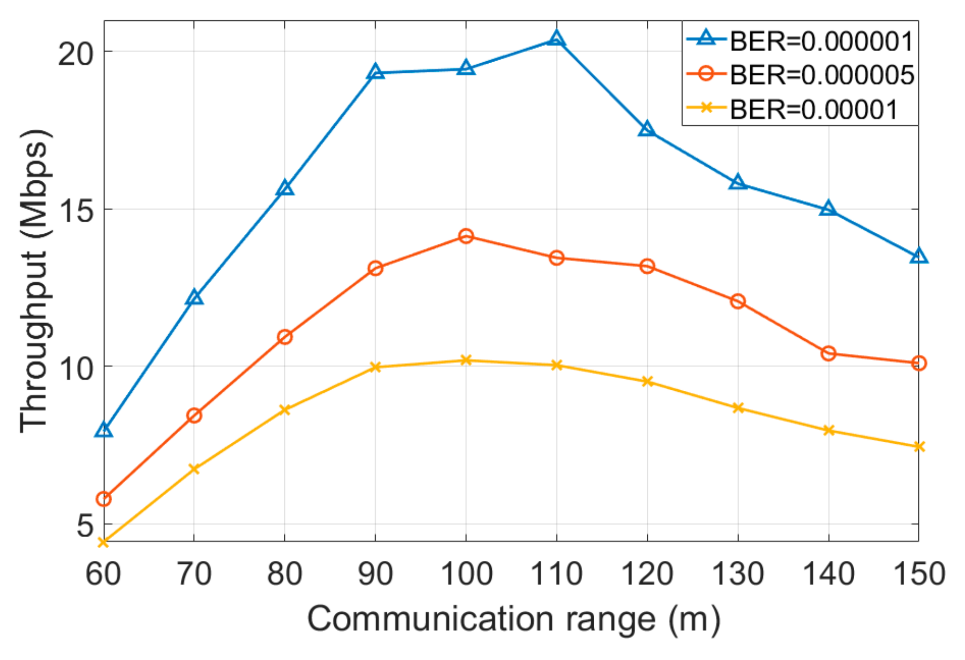
4.3. Channel Conditions
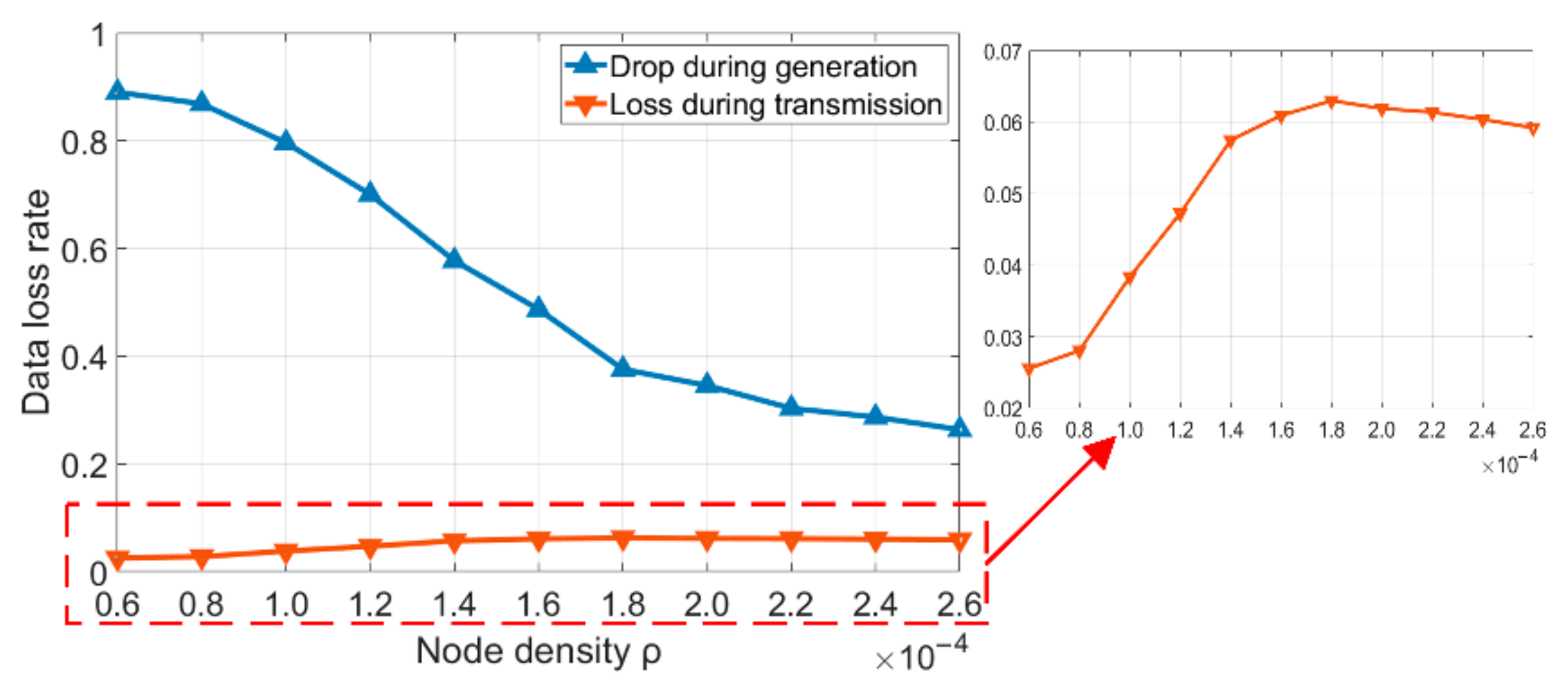
The performance of UV communication networks is dependent on the performance of UV point-to-point communication systems. Factors such as atmospheric turbulence and background noise affect these systems, which are ultimately reflected in communication coverage, data rate, and BER. In current research, due to significant path loss during atmospheric propagation of UV light, the communication rate at hundred-meter distances typically ranges from 100 Kbps to 10 Mbps. In this section, the basic simulation conditions are set as follows: communication coverage of 100 m, point-to-point data rate of 10 Mbps, and BER of 10−6. However, as channel conditions such as atmospheric turbulence change, the performance of the communication system may improve or deteriorate, manifested as reduced communication range, increased BER, etc.
By setting parameters such as different communication coverage and BER, the network performance under varying channel conditions can be simulated. Figure 6 simulates the network performance when n is 100, ρ is 0.00012, the link rate is 10 Mbps, and λ is 0.7, as the node communication distance gradually extends from 60 m to 150 m with changing channel conditions. The results show that as the communication distance increases, the network throughput exhibits a trend of first increasing and then decreasing. This is because when the communication distance is short and the network density is low, the network is highly likely to be partitioned into multiple independent subnets or isolated nodes. In this case, the actual transmittable data of nodes is significantly reduced, a phenomenon that improves as channel conditions improve and node communication distance increases. However, when network density remains constant, further increasing the node communication distance leads to a further decline in total network throughput. This is because, as the node communication distance increases, the number of one-hop neighbors for each node also increases. Consequently, whenever a transmission path is successfully established, more nodes enter the silent state, which reduces the number of simultaneously established transmission paths in the network.
Additionally, Figure 6 demonstrates that network throughput decreases significantly when channel conditions deteriorate and BER increases. This occurs because a higher BER not only leads to data frame transmission failures but, more critically, elevates the probability of nodes constructing incorrect connection matrices. Once a node establishes an erroneous connection matrix, it may trigger a cascade of transmission failures for multiple paths until the next neighbor discovery cycle.
Thus, in practical implementations, adjusting parameter settings according to specific application scenarios is imperative. Under favorable channel conditions, nodes can be deployed across a broader operational space; when channel conditions degrade, the network should reduce deployment span and increase node density to ensure optimal performance.

4.4. Node Density

When node density ρ is low, the number of relays required for communication between nodes increases, and the network is more likely to be partitioned into multiple disjoint subnets as nodes move. When node density is high, connections between nodes become tighter. In this case, each established transmission path occupies more nodes, leading to a reduction in the number of simultaneously establishable transmission paths. Both scenarios may have adverse effects on network performance. This section simulates the impact of ρ on network performance. v is set to 10 mps, the arrival rate λ is 0.7, the number of nodes is 100, the link rate remains at 10 Mbps, the bit error rate is 10−6, the communication range is 100 m, and Tref is approximately equal to 10Ttrans.
In LSM-UVCN, each node in the network follows the equal probability principle to randomly select any node as the destination node for data transmission. If the source node and the destination node belong to non-connected subnets, the source node will directly discard the data. As shown in Figure 7, when ρ is low, the probability that data is directly discarded upon generation is relatively high, and this probability decreases significantly as ρ increases. Compared with the case when ρ = 0.00006, the probability of direct data discarding decreases by approximately 0.62 when ρ = 0.00026. Additionally, during data transmission, the probability of transmission failure caused by path breakage or interference between paths shows a trend of first rising rapidly and then gradually decreasing with the increase of ρ. When ρ = 0.00014, the data loss rate increases by approximately 0.032 compared with that when ρ = 0.00006.
As ρ decreases continuously, the network is highly likely to split into multiple independent and non-interfering subnets. In this situation, the probability that nodes directly discard the generated data increases significantly. As ρ gradually increases, most nodes in the network are located in the same subnet, and the probability of direct data discarding drops sharply. However, during data transmission, the probability of transmission failure due to path breakage or interference between paths exhibits a non-linear trend of first increasing and then decreasing with the change of ρ. When ρ is low, the network is highly likely to split into multiple independent subnets. The distance between nodes and the number of nodes within each subnet are relatively limited, resulting in transmission paths mainly composed of short-distance links. According to the theoretical derivations of Equations (3) and (6), in a network environment dominated by short links, the probability of successful data transmission is relatively high.
Figure 8 simulates the number of transmission paths of different lengths established per second on average in the network under different values of ρ. It can be observed that as ρ gradually increases, the number of transmission paths generated per second in the network increases significantly. However, as ρ continues to rise, the generation rate of transmission paths begins to decline. Figure 8 also reveals that the rate of generating long-distance transmission paths first increases and then decreases with the growth of ρ. When ρ = 0.00006, the rate of generating transmission paths with more than five hops is approximately 22% of the rate of generating paths within one hop. When ρ increases to 0.00012, this rate rises to 45%.
As ρ increases, more nodes become interconnected, forming larger subnets. This leads to a rapid decrease in the probability of nodes discarding generated data, providing more data transmission opportunities and significantly enhancing the likelihood of forming long-distance transmission paths. Consequently, both link complexity and interference risks increase, elevating the probability of data transmission failure. When ρ continues to increase, the average distance between nodes decreases significantly, reducing the network coverage area. Under such conditions, each newly established transmission path occupies a larger number of silent nodes, resulting in a notable decrease in the number of parallel transmission paths and thus reducing the overall number of transmission paths established per second. Simultaneously, when the total number of nodes is fixed, the reduction in inter-node distance decreases the generation rate of long-distance transmission paths but improves the reliability of data transmission, as shown in Figure 7 and Figure 8.
In summary, according to the theoretical model of Equation (11), there exists a close functional relationship between the network throughput, the number of parallel transmission paths Npath, and the transmission bandwidth per path Bpath. Although both the path generation rate and the transmission failure probability initially increase and then decrease with the increase of ρ, the growth rate of the path generation rate significantly exceeds that of the transmission failure probability. Consequently, the network throughput exhibits a characteristic of first increasing and then decreasing as ρ increases, as shown in Figure 9.
Based on this analysis, the following conclusions can be drawn: When the initial ρ value is low, as ρ increases, nodes gain more transmission opportunities, leading to a rapid rise in the transmission path generation rate. Although the increase in long-distance transmission paths elevates the transmission failure probability, the growth rate of the path generation rate far surpasses that of the failure probability, resulting in an upward trend in network throughput. As ρ continues to increase, the network topology further contracts, shortening the inter-node distances. This contraction increases the number of silent nodes occupied by each transmission path, thereby reducing the path generation rate. Although the reduction in long-distance paths when ρ is sufficiently large decreases the transmission failure probability, the decline in the path generation rate outweighs the decrease in failure probability, leading to a reduction in the overall network throughput.

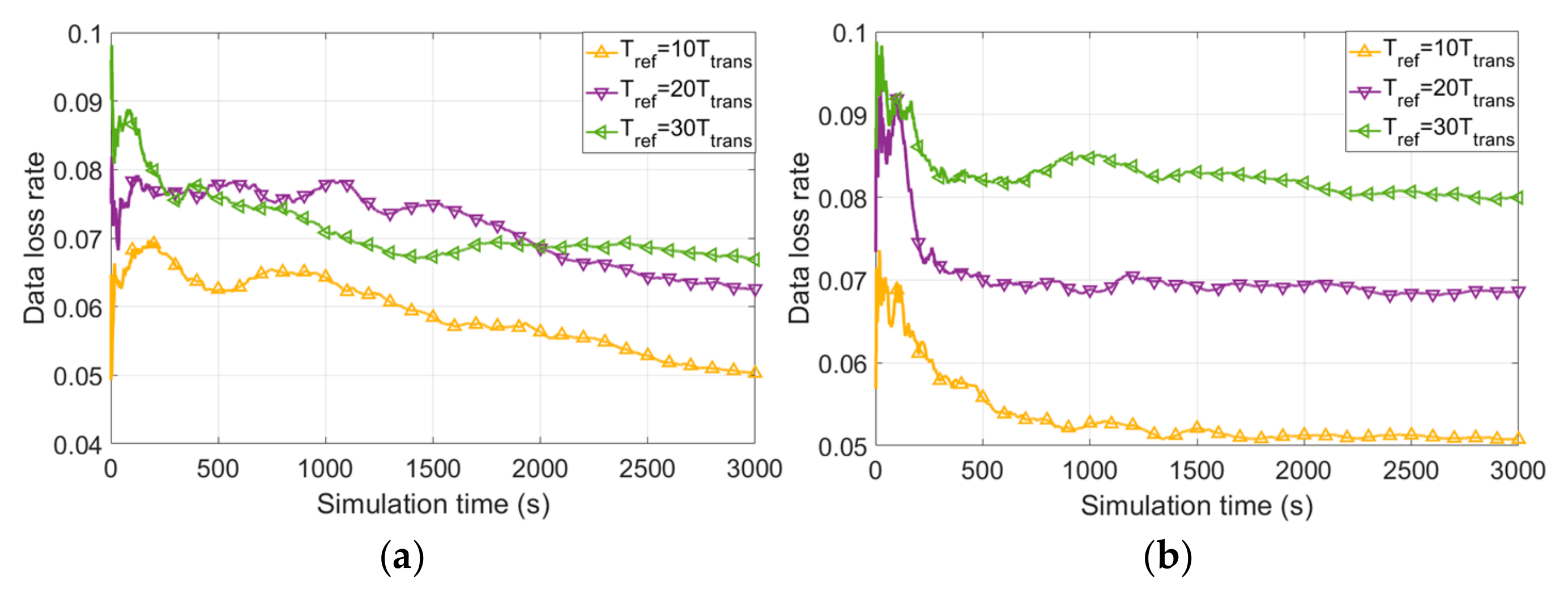
4.5. Node Speed and Tref

LSM-UVCN relies on the established connection matrix. As the network topology evolves with node mobility, transmission paths established based on outdated connection matrices are highly susceptible to issues such as path disruption or mutual interference between paths, thus leading to transmission failures. In the random movement model, a larger velocity v implies more frequent changes in network topology, making the connection matrix more prone to obsolescence. The proposed protocol mitigates the adverse effects of connection matrix obsolescence to a certain extent through periodic updates of the connection matrix. This section simulates the impact of v and Tref on network performance, where the node density ρ is configured as 0.00012 and other conditions remain unchanged.
Figure 10 illustrates the impact of adjusting Tref on the data loss rate under different v. When v = 5 mps, reducing Tref from 30Ttrans to 10Ttrans decreases the data loss rate by approximately 0.017. In contrast, when v = 15 mps, the same adjustment to Tref results in a reduction of approximately 0.029. This discrepancy arises because, at lower v, the intensity of network topology changes is relatively low; consequently, increasing Tref has a diminished effect on the data loss rate.
In Figure 10, the data loss rate exhibits a characteristic trend: it initially decreases rapidly, followed by a gradual stabilization through oscillatory behavior. Specifically, in Figure 10b, the data loss rate enters a stable oscillatory state after approximately 1000 s of simulation time. Conversely, in Figure 10a, the data loss rate declines more slowly and does not stabilize until around 3000 s. This divergence is attributed to the network compactness, which influences network performance 20. When ρ is fixed, network compactness fluctuates within a certain range due to random node mobility, thereby causing temporal variations in the data loss rate. Notably, the simulation settings specify constant network density and initial topology, resulting in a relatively stable initial data loss rate. Notably, the simulation parameters include fixed network density and initial topology, which anchor the initial data loss rate at a relatively stable baseline. Higher v accelerates topological changes, enabling the network to reach oscillatory stability more rapidly.
Figure 11 illustrates the impact of adjusting v on the data loss rate under different values of Tref. When Tref is small, the network can update the connection matrix in a timely manner, significantly reducing data transmission failures caused by outdated connection matrices. As shown in Figure 11a, setting a lower Tref mitigates performance degradation arising from intensified network topology changes at higher v. Conversely, when Tref is large, the influence of network topology change intensity on the data loss rate becomes more pronounced, as demonstrated in Figure 11b. For example, when Tref = 30Ttrans, the data loss rate at v = 15 mps is approximately 0.013 higher than that at v = 5 mps.
Therefore, adjusting the magnitude of Tref according to different network mobility states can optimize network performance.

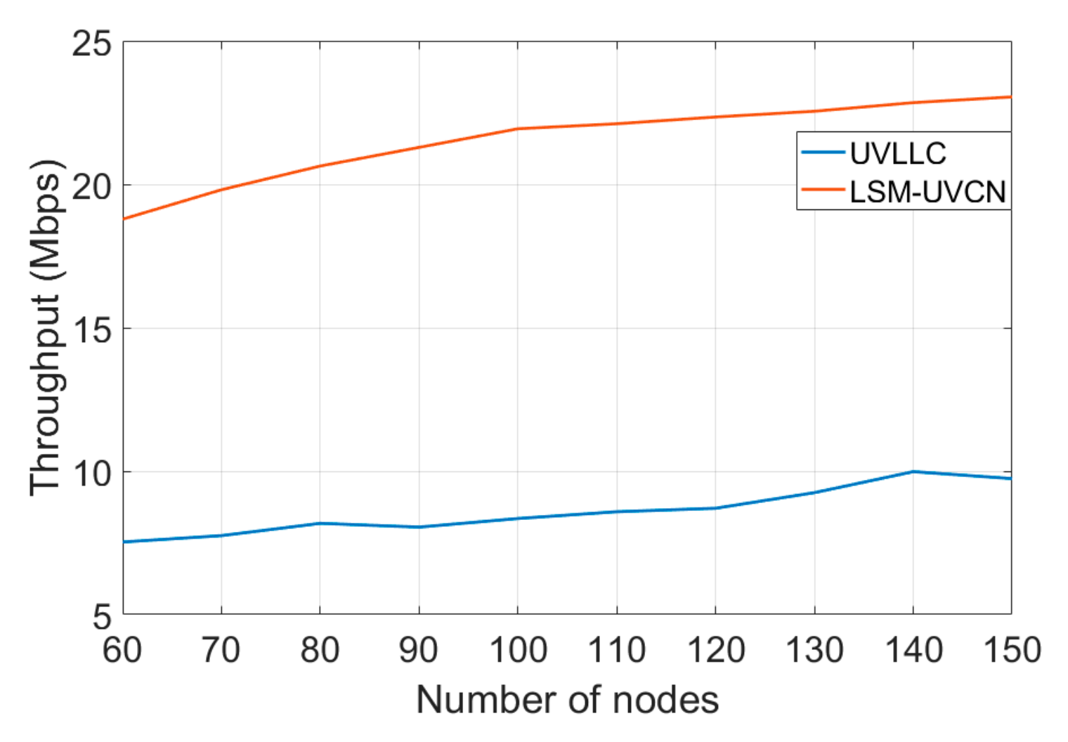
4.6. Protocol Performance Comparison

The proposed protocol is based on the UV lossless competition protocol in multi-hop networks (UVLLC). The lossless competition mechanism and bit simultaneous transmission mechanism have been experimentally validated in [15,16,17]. However, the lossless competition protocol in multi-hop networks essentially ensures that “one node successfully transmits data per time slot” across the network, regardless of its scale. In networks with a small number of nodes, this protocol demonstrates superior network performance. Nevertheless, as the network scale expands, the protocol still maintains the constraint of “only one node transmitting data successfully per time slot”, failing to fully utilize node resources. This section analyzes and compares the performance of the two protocols under different network scales, where ρ is set to 0.00012, v is 10 mps, Tref = 10Ttrans, and other simulation conditions remain unchanged.
As shown in Figure 12, the mechanism of “only one node can transmit data per time slot” helps UVLLC achieve lossless contention, but it fails to further improve throughput as the network scale expands. Only when the network is partitioned into multiple disjoint subnets due to node mobility can it passively allow multiple nodes to transmit data simultaneously. By contrast, LSM-UVCN actively utilizes nodes in the silent state to set up “isolation zones”, which fully leverages node resources and enhances throughput by establishing more transmission paths concurrently.

5. Conclusions

To address the networking needs of large-scale mobile UV optical networks, this paper proposes a novel protocol. It employs a lossless competition mechanism, designs a low-overhead neighbor discovery algorithm, and introduces a “competition-first-then-transmission” approach for spatial division multiplexing, significantly boosting network performance. For dynamic topology changes due to node mobility, a periodic neighbor discovery mechanism maintains the connection matrix in real-time, mitigating mobility impacts and ensuring stable operation.
The routing strategy uses a shortest-path algorithm prioritizing high-priority nodes to minimize relaying. Given the limited resources and high mobility of UAV-based UV network nodes, parameters like residual energy and one-hop neighbor count are critical for routing. Future work will integrate these metrics into routing algorithms to optimize network lifetime, enhance throughput, and strengthen adaptability in complex environments, supporting engineering applications of large-scale mobile UV networks.

Author Contributions

Conceptualization, L.W., Z.X. and J.L.; methodology, L.W.; software, L.W.; validation, J.Z.; formal analysis, Y.S.; writing—original draft preparation, L.W.; writing—review and editing, C.L.; funding acquisition, J.L. and J.W. All authors have read and agreed to the published version of the manuscript.

Funding

This research was supported by the National Natural Science Foundation of China (Grant No. 62171463, Jianhua Li; Grant No. 62271502, Jingyuan Wang) and the Natural Science Foundation of Jiangsu Province (Grant No. BK20231486, Jingyuan Wang).

Data Availability Statement

The original contributions presented in this study are included in the article. Further inquiries can be directed to the corresponding author.

Conflicts of Interest

The authors declare no conflicts of interest.

References

  1. Luo, P.; Zhang, M.; Liu, Y.; Han, D. A moving average filter based method of performance improvement for ultraviolet communication system. In Proceedings of the International Symposium on Communication Systems, Poznan, Poland, 18–20 July 2012; IEEE: New York, NY, USA, 2012. [Google Scholar] [CrossRef]
  2. Zhang, M.; Luo, P.; Guo, X.; Zhang, X.; Han, D.; Li, Q. Spread spectrum-based ultraviolet communication with experiments. Chin. Opt. Lett. 2014, 12, 100602. [Google Scholar] [CrossRef]
  3. Han, D.; Gu, Y.; Zhang, M. Experimental study of an optimized PSP-OSTBC scheme with m-PPM in ultraviolet scattering channel for optical MIMO system. Appl. Opt. 2017, 56, 6564. [Google Scholar] [CrossRef] [PubMed]
  4. Deng, Y.; Wang, Y.; Zhang, Y.; Du, A.; Liu, J. The realization of a wide-angle voice transmission non-line-of-sight ultraviolet communication system. J. Semicond. 2021, 42, 47–52. [Google Scholar] [CrossRef]
  5. Du, A.; Wang, Y.; Zhang, J.; Zhao, Y.; Sun, N.; Liu, J. Characteristic Study of Non-Line-of-Sight Scattering Ultraviolet Communication System at Small Elevation Angle. Photonics 2022, 9, 363. [Google Scholar] [CrossRef]
  6. Chen, X.; Han, D.; Zhang, M.; Ren, T.; Wan, T. Experimental research on image transmission over one hundred meters with limited bandwidth in a semantic ultraviolet communication system. In Proceedings of the 2024 14th International Symposium on Communication Systems, Networks and Digital Signal Processing (CSNDSP), Rome, Italy, 17–19 July 2024. [Google Scholar] [CrossRef]
  7. Du, A.; Wang, Y.; Zhang, J.; Zou, C.; Xiang, Z.; Liu, J.; Xue, C. Implementation of large angle low error non-line-of-sight ultraviolet communication system. Opt. Commun. 2024, 558, 130227. [Google Scholar] [CrossRef]
  8. Zhang, X.; Zhao, S.; Li, Y.; Deng, B.; Cheng, Z. A subsection Operation Back-off Algorithm of MAC Layer in Airborne Ultraviolet Communication Network. Semicond. Optoelectron. 2015, 36, 5. [Google Scholar] [CrossRef]
  9. Zhang, X.; Zhao, S.; Li, Y.; Deng, B.; Cheng, Z. Multi-channel directional media access control protocol for air borne ultraviolet communication based on space division multiplexing. Laser Technol. 2016, 40, 5. [Google Scholar] [CrossRef]
  10. Li, J.; Liu, X.; Wang, H.; Wu, X. Improved Ultraviolet Communication Time Division Multiplexing Network Method. Chin. J. Lasers 2014, 41, 1105003. [Google Scholar] [CrossRef]
  11. Li, C.; Xu, Z.; Wang, J.; Zhao, J.; Wang, L.; Wang, Y.; Li, J. Enhanced collaborative networking protocol based on clustering mechanism for UV networks. Opt. Commun. 2024, 560, 130464. [Google Scholar] [CrossRef]
  12. Yang, J.; Luo, J.L.; Chen, X.Y.; Cheng, F. UVAd-TDMA: An MAC Protocol for the solar blind ultraviolet Ad-Hoc network. Appl. Mech. Mater. 2014, 543–547, 2854–2857. [Google Scholar] [CrossRef]
  13. Pan, Y.; Zhang, Y.; Long, F.; Li, P.; Shi, H.; Shi, J. Beacon-enabled TDMA Ultraviolet Communication Network System Design and Realization. In Proceedings of the 2024 14th International Symposium on Communication Systems, Networks and Digital Signal Processing (CSNDSP), Rome, Italy, 23 August 2024; IEEE: New York, NY, USA, 2024. [Google Scholar] [CrossRef]
  14. Yang, J.; Li, X.Y.; Zhao, F.; Chen, X.Y.; Shao, P. An Algorithm of Channel Sharing for the Solar Blind NLOS Ultraviolet Ad-Hoc Network Based on the Hybrid Genetic Algorithm. Appl. Mech. Mater. 2014, 543–547, 2850–2853. [Google Scholar] [CrossRef]
  15. Li, C.; Li, J.; Xu, Z.; Wang, J. Research on the lossless contention MAC protocol and the performance of an ultraviolet communication network. Opt. Express 2021, 29, 31952–31962. [Google Scholar] [CrossRef] [PubMed]
  16. Li, C.; Li, J.; Wang, J.; Zhao, J.; Gao, G.; Wang, K.; Su, Y.; Xu, Z. QoS based enhanced lossless contention MAC protocol for ultraviolet network. Opt. Express 2022, 30, 31439–31455. [Google Scholar] [CrossRef] [PubMed]
  17. Li, C.; Xu, Z.; Li, J.; Wang, J.; Lin, Y.; Zhao, J.; Qi, A.; Shen, H. Performance of the UV Multi-node Network Under the Lossless Contention MAC Protocol. IEEE Photonics J. 2022, 14, 3156550. [Google Scholar] [CrossRef]
  18. Wang, L.; Xu, Z.; Wang, J.; Zhao, J.; Wang, Y.; Li, J. Lossless contention ultraviolet MAC protocol based on dynamic bandwidth allocation. J. Opt. Commun. Netw. 2024, 16, 941–955. [Google Scholar] [CrossRef]
  19. Wang, L.; Xu, Z.; Wang, J.; Zhao, J.; Wang, Y.; Ma, X.; Li, J. Ultraviolet collaborative networking method based on a novel neighbor discovery algorithm. Opt. Commun. 2024, 568, 12. [Google Scholar] [CrossRef]
  20. Wang, L.; Xu, Z.; Wang, J.; Li, C.; Hu, J.; Su, Y.; Li, J. MAC protocol for implementing SDM in large-scale ultraviolet networks. Opt. Express 2025, 33, 21584–21604. [Google Scholar] [CrossRef] [PubMed]
Figure 1. Distance determination: (a) example of network topology; (b) example of the distance determination process; (c) the second-type control frame of Node 2 features an added “neighbors segment” compared to the first-type control frame.
Photonics 12 00710 g001
Figure 2. Generation of the network connection matrix.
Photonics 12 00710 g002
Figure 3. The complete workflow of the networking protocol.
Photonics 12 00710 g003
Figure 4. Hop-by-hop neighbor table and path establishment example.
Photonics 12 00710 g004
Figure 5. Example of path generation and state transition.
Photonics 12 00710 g005
Figure 6. Throughput versus number of nodes and BER.
Photonics 12 00710 g006
Figure 7. Data loss rate versus node density ρ.
Photonics 12 00710 g007
Figure 8. Transmission path generation rate versus node density ρ.
Photonics 12 00710 g008
Figure 9. Throughput versus node density ρ.
Photonics 12 00710 g009
Figure 10. Data loss rate versus different v: (a) v = 5 mps; (b) v = 15 mps.
Photonics 12 00710 g010
Figure 11. Data loss rate versus different Tref: (a) Tref = 10Ttrans; (b) Tref = 30Ttrans.
Photonics 12 00710 g011
Figure 12. Throughput comparison of UVLLC and LSM-UVCN.
Photonics 12 00710 g012
Table 1. Basic parameters in the analysis.
ParameterMeaning
nTotal number of nodes
LSide length of the node distribution area, and the area of the distribution area is L × L
ρNode density, ρ = n/L2
AMaximum communication distance of nodes
BERBit error rate
TclkThe time of each clock cycle
Table 2. Basic parameters in the simulation.
ParameterValueMeaning
Communication coverage100 mThe maximum communication distance from point to point
Tdata25 msThe time of each data transmission time slot
Link rate10 MbpsThe maximum communication rate from point to point
Simulation time3000 sThe duration of the simulation
BER10−6Bit error rate
n100Number of nodes
A-Area of the distribution region
ρ-Node density, ρ = n/A
λ-At each node, the arrival of data follows a Poisson distribution with intensity λ.
Ttrans-The time required for a complete transmission cycle, Ttrans ≈ 5 ms
Tref-Network connection matrix update period
v-The moving speed of nodes, in meters per second (mps)
Disclaimer/Publisher’s Note: The statements, opinions and data contained in all publications are solely those of the individual author(s) and contributor(s) and not of MDPI and/or the editor(s). MDPI and/or the editor(s) disclaim responsibility for any injury to people or property resulting from any ideas, methods, instructions or products referred to in the content.

