A Review of the Research Progress on Optical Fiber Sensors Based on C-Type Structures


Abstract
1. Introduction
2. Structural Design of C-Type Optical Fibers
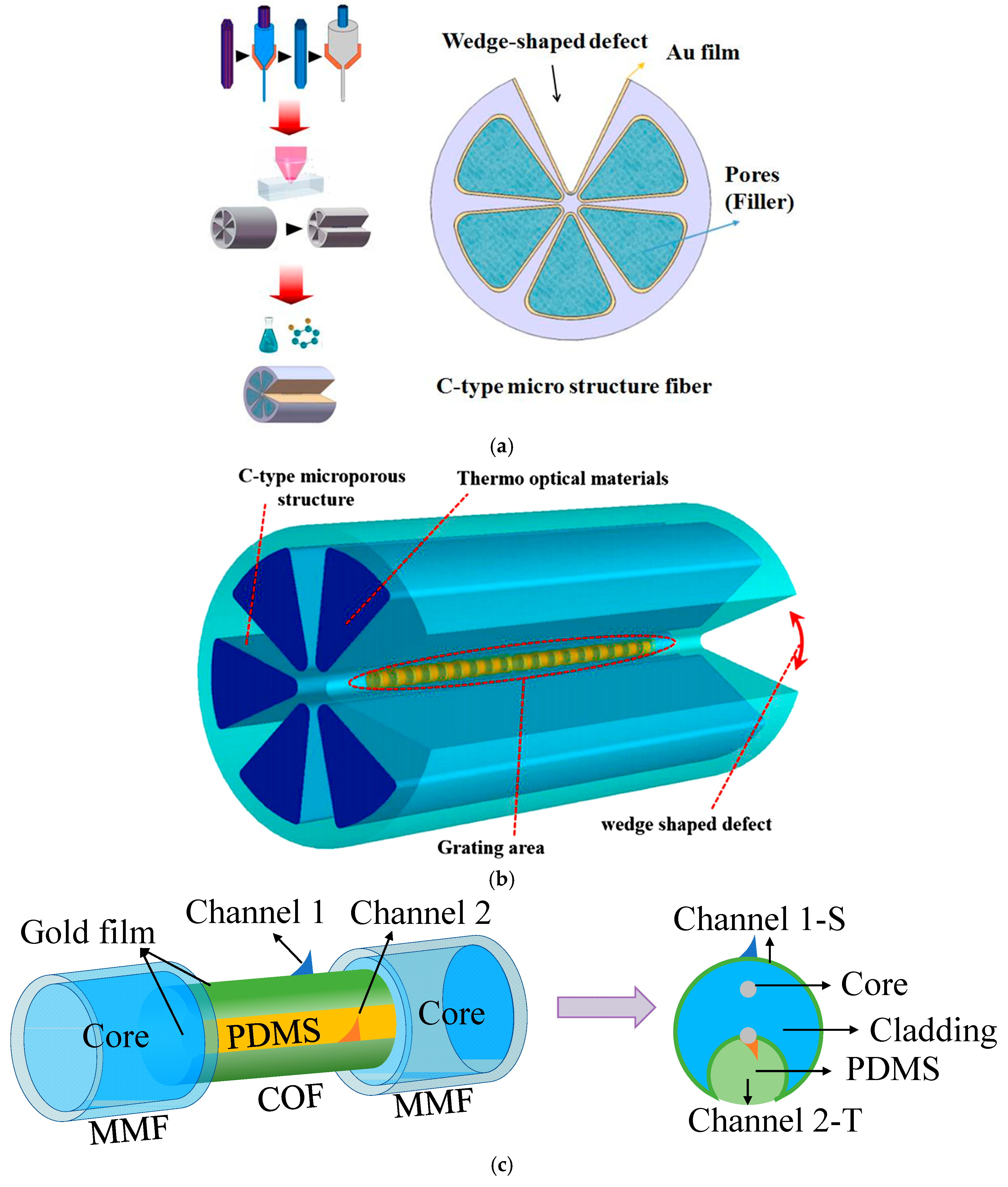
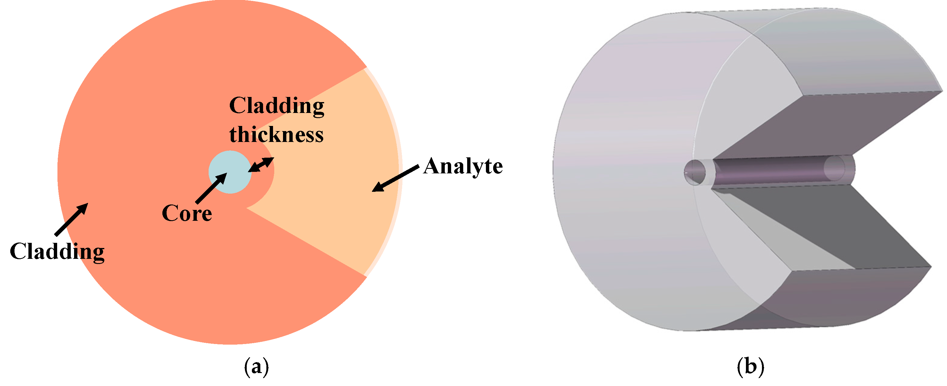
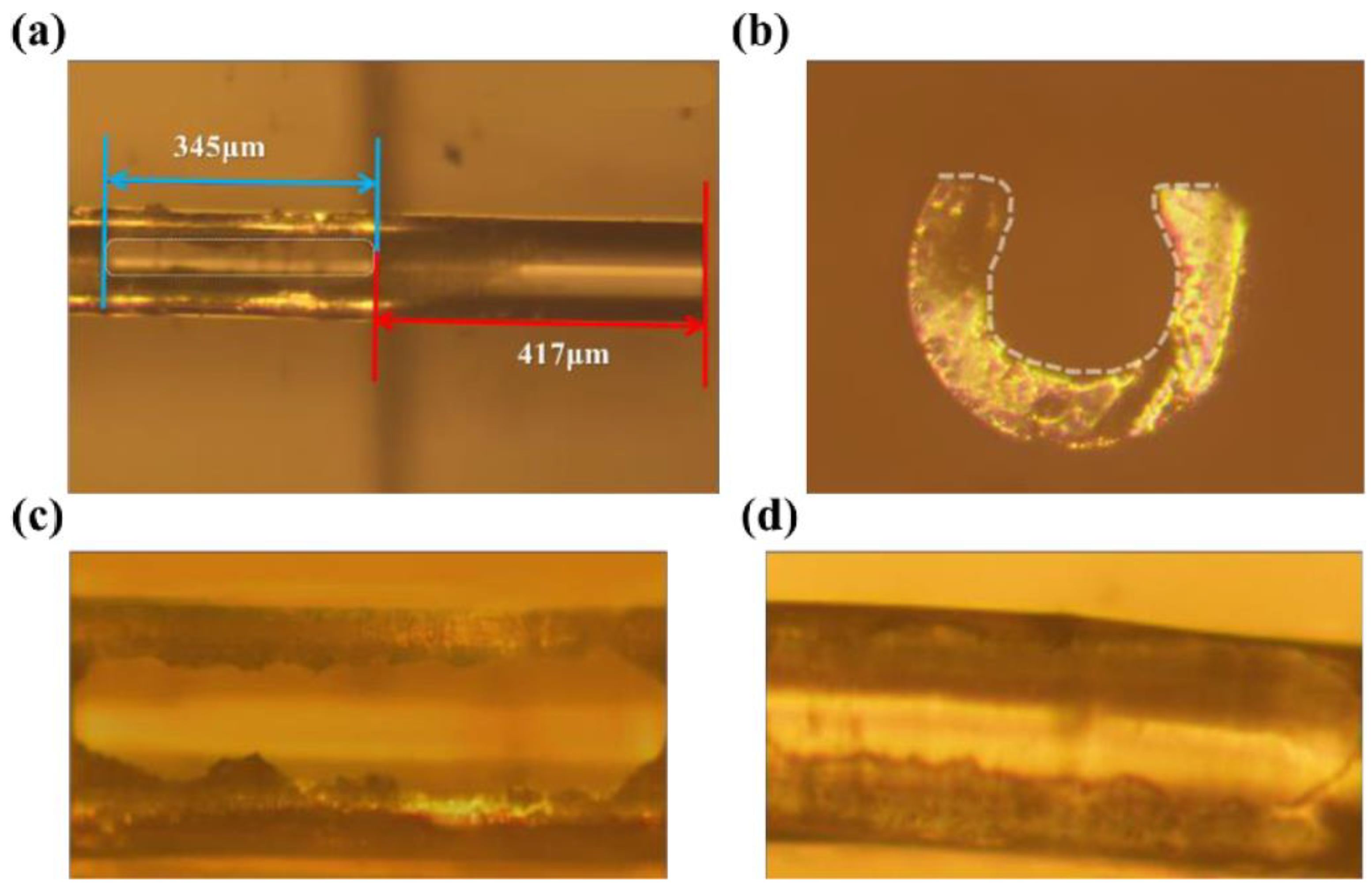
2.1. Structural Design and Fabrication of C-Type Optical Fibers
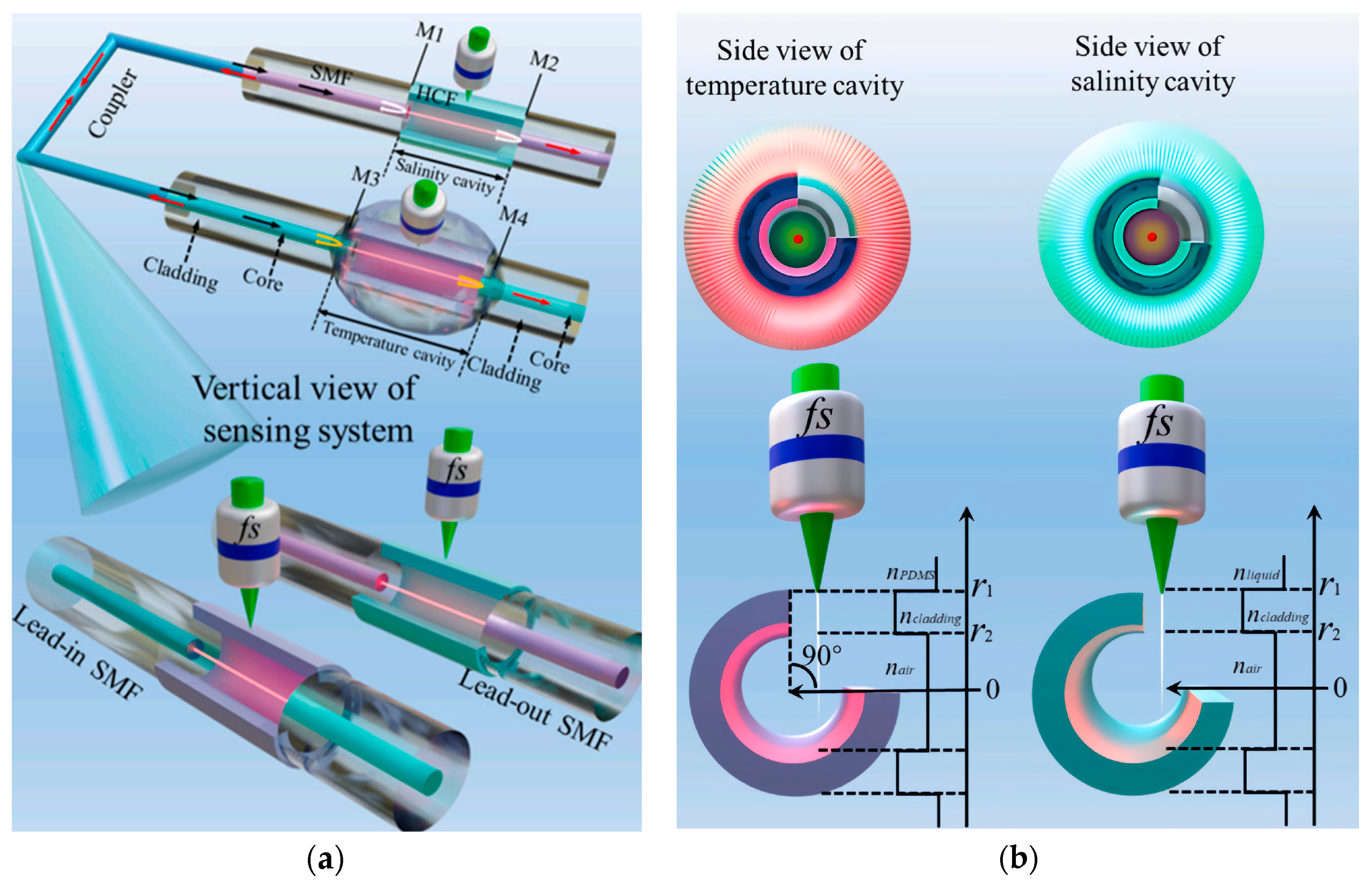
2.2. Working Principle of C-Type Fiber Sensors
3. Interferometric Optical Fiber Sensor Based on C-Type Structure
3.1. Interference Principle
3.2. Fabry–Perot Interferometer Based on C-Type Optical Fiber
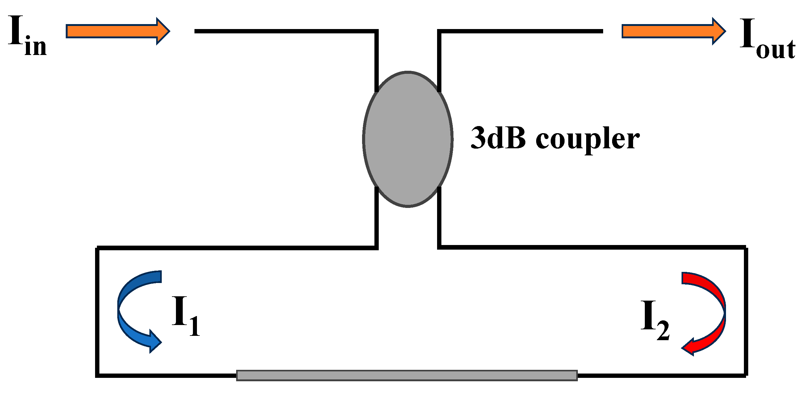
3.3. Sagnac Interferometer Based on C-Type Optical Fiber
3.4. Mach–Zehnder Interferometer Based on C-Type Optical Fiber
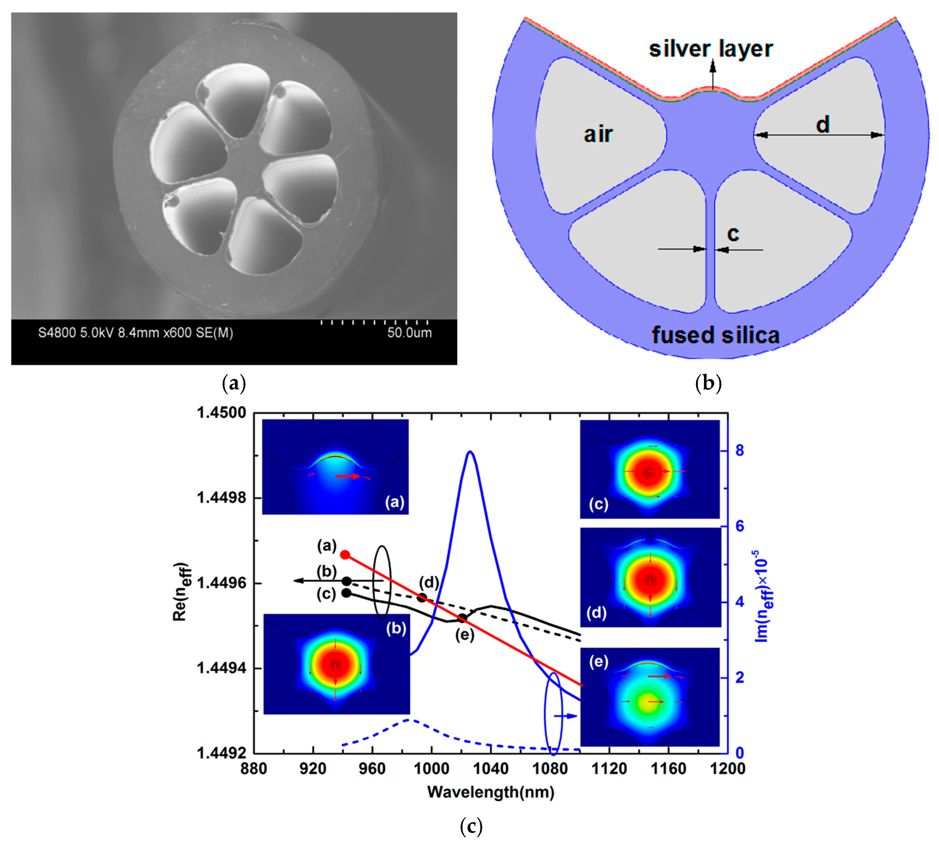
4. C-Type PCF Based on SPR
4.1. Improvements in C-Type PCF-SPR Sensors Through Metal Layer Optimization
4.2. Multi-Parameter Performance Analysis of C-Type PCF-SPR Sensors
5. Potential Future Directions
6. Conclusions
Author Contributions
Funding
Conflicts of Interest
References
- Marques, C.; Leal-Júnior, A.; Kumar, S. Multifunctional integration of optical fibers and nanomaterials for aircraft systems. Materials 2023, 16, 1433. [Google Scholar] [CrossRef] [PubMed]
- Kavitha, B.S.; Pant, S.; Sood, A.K.; Asokan, S. Fiber grating sensors and their recent applications in biomedical domain. J. Opt. 2023, 25, 084001. [Google Scholar]
- Lyu, D.; Huang, Q.; Wu, X.; Nie, Y.; Yang, M. Optical fiber sensors for water and air quality monitoring: A review. Opt. Eng. 2024, 63, 031004. [Google Scholar] [CrossRef]
- Jin, W.; Xu, M.; Zhang, L.; Zhang, X.; Qi, Y. Seawater salinity detection based on elliptical micro/nano fiber optic probe sensing. Opt. Eng. 2021, 60, 127111. [Google Scholar] [CrossRef]
- Al Zain, M.; Karimi-Alavijeh, H.; Moallem, P.; Khorsandi, A.; Ahmadi, K. A high-sensitive fiber specklegram refractive index sensor with microfiber adjustable sensing area. IEEE Sens. J. 2023, 23, 15570–15577. [Google Scholar] [CrossRef]
- Chen, C.H.; Tsao, T.C.; Tang, J.L.; Wu, W.T. A multi-D-shaped optical fiber for refractive index sensing. Sensors 2010, 10, 4794–4804. [Google Scholar] [CrossRef]
- Kassani, S.H.; Khazaeinezhad, R.; Jung, Y.; Kobelke, J.; Oh, K.; Lee, B.; Lee, S.-B.; Rao, Y. In-line chemical sensor based on C-type fiber and novel photonic crystal fibers with high sensitivity and fast dynamic response. In Proceedings of the Fifth Asia-Pacific Optical Sensors Conference, Jeju, Republic of Korea, 20–22 May 2015; Volume 9655, pp. 148–151. [Google Scholar]
- Kassani, S.H.; Park, J.; Park, M.; Oh, K. Sensitivity enhancement of in-line chemical sensing device with C-type fiber and photonic crystal fiber. In Proceedings of the Fiber Lasers IX: Technology, Systems, and Applications, San Francisco, CA, USA, 21–26 January 2012; Volume 8237, pp. 366–373. [Google Scholar]
- Tan, R.X.; Ho, D.; Tse, C.H.; Tan, Y.C.; Yoo, S.W.; Tjin, S.C.; Ibsen, M. Birefringent Bragg grating in C-shaped optical fiber as a temperature-insensitive refractometer. Sensors 2018, 18, 3285. [Google Scholar] [CrossRef]
- Razali, N.M.; Ambran, S.; Zuikafly, S.N.F.; Yuzir, M.A.M.; Sapingi, H.H.J. Design and Simulation of C-Shaped Optical Fiber Sensor. In Proceedings of the 2021 International Conference on Numerical Simulation of Optoelectronic Devices (NUSOD), Turin, Italy, 13–17 September 2021; pp. 109–110. [Google Scholar]
- Razali, N.M.; Ambran, S.; Holmes, C.; Zuikafly, S.N.F.; Lokman, M.Q.; Yuzir, A.; Sapingi, H.H.J. Design optimisation of C-shaped optical fibre sensor. Opt. Quantum Electron. 2022, 54, 421. [Google Scholar] [CrossRef]
- Lin, Z.T.; Zhao, Y.; Zhao, R.; Cai, L.; Hu, X.-G.; Peng, Y. High-sensitivity and low-loss vector magnetic field sensor based on the C-type optical fiber. IEEE Trans. Magn. 2021, 57, 4002308. [Google Scholar] [CrossRef]
- Kuznetsov, P.I.; Sudas, D.P.; Savel’Ev, E.A. Formation of fiber tapers by chemical etching for application in fiber sensors and lasers. Instrum. Exp. Tech. 2020, 63, 516–521. [Google Scholar] [CrossRef]
- Riza, M.A.; Go, Y.I.; Maier, R.R.J.; Harun, S.W.; Anas, S.B.A. Enhanced fiber mounting and etching technique for optimized optical power transmission at critical cladding thickness for fiber-sensing application. Laser Phys. 2021, 31, 126201. [Google Scholar] [CrossRef]
- Tang, J.; Zhou, J.; Guan, J.; Long, S.; Yu, J.; Guan, H.; Lu, H.; Luo, Y.; Zhang, J.; Chen, Z. Fabrication of side-polished single mode-multimode-single mode fiber and its characteristics of refractive index sensing. IEEE J. Sel. Top. Quantum Electron. 2016, 23, 238–245. [Google Scholar] [CrossRef]
- Lei, L.; Li, H.; Shi, J.; Hu, Q.; Zhao, X.; Wu, B.; Wang, M.; Wang, Z. Miniature Fabry-Perot cavity based on fiber Bragg gratings fabricated by Fs laser micromachining technique. Nanomaterials 2021, 11, 2505. [Google Scholar] [CrossRef]
- Fedotov, A.B.; Serebryannikov, E.E.; Zheltikov, A.M.; Sidorov-Biryukov, D.A.; Zhou, P.; Tarasevitch, A.P.; Linde, D.; Hu, M.L.; Li, Y.; Wang, C.Y.; et al. Laser micromachining of microstructure fibers with femtosecond pulses. Laser Phys. 2003, 13, 657–663. [Google Scholar]
- Vasquez, A.; Samolis, P.; Zeng, J.; Sander, M.Y. Micro-structuring, ablation, and defect generation in graphene with femtosecond pulses. OSA Contin. 2019, 2, 2925–2934. [Google Scholar] [CrossRef]
- Mincuzzi, G.; Audouard, E.; Bourtereau, A.; Delaigue, M.; Faucon, M.; Hoenninger, C.; Mishchik, K.; Rebière, A.; Sailer, S.; Seweryn-Schnur, A.; et al. Pulse to pulse control for highly precise and efficient micromachining with femtosecond lasers. Opt. Express 2020, 28, 17209–17218. [Google Scholar] [CrossRef]
- Tatian, B. Fitting refractive-index data with the Sellmeier dispersion formula. Appl. Opt. 1984, 23, 4477–4485. [Google Scholar] [CrossRef]
- Sukhoivanov, I.A.; Guryev, I.V. Photonic Crystals: Physics and Practical Modeling; Springer: Berlin/Heidelberg, Germany, 2009. [Google Scholar]
- Slawinski, M.A.; Slawinski, R.A.; Brown, R.J.; Parkin, J.M. A generalized form of Snell’s law in anisotropic media. Geophysics 2000, 65, 632–637. [Google Scholar] [CrossRef]
- Felsen, L.B. Evanescent waves. J. Opt. Soc. Am. 1976, 66, 751–760. [Google Scholar] [CrossRef]
- Zhao, N.Z.; Williamson, I.A.D.; Zhao, Z.; Boutami, S.; Fan, S. Penetration depth reduction with plasmonic metafilms. ACS Photonics 2019, 6, 2049–2055. [Google Scholar] [CrossRef]
- Miliou, A. In-fiber interferometric-based sensors: Overview and recent advances. Photonics 2021, 8, 265. [Google Scholar] [CrossRef]
- Zhu, C.; Zhuang, Y.; Liu, B.; Huang, J. Review of fiber optic displacement sensors. IEEE Trans. Instrum. Meas. 2022, 71, 7008212. [Google Scholar] [CrossRef]
- Dattner, Y.; Yadid-Pecht, O. Analysis of the effective refractive index of silicon waveguides through the constructive and destructive interference in a Mach–Zehnder interferometer. IEEE Photonics J. 2011, 3, 1123–1132. [Google Scholar] [CrossRef]
- Niciejewski, R.J.; Killeen, T.L.; Turnbull, M. Ground-based Fabry-Perot interferometry of the terrestrial nightglow with a bare charge-coupled device: Remote field site deployment. Opt. Eng. 1994, 33, 457–465. [Google Scholar] [CrossRef]
- Koskinen, V.; Fonsen, J.; Kauppinen, J.; Kauppinen, I. Extremely sensitive trace gas analysis with modern photoacoustic spectroscopy. Vib. Spectrosc. 2006, 42, 239–242. [Google Scholar] [CrossRef]
- Li, J.; Li, Z.; Yang, J.; Zhang, Y.; Ren, C. Microfiber Fabry-Perot interferometer used as a temperature sensor and an optical modulator. Opt. Laser Technol. 2020, 129, 106296. [Google Scholar] [CrossRef]
- Lee, C.L.; Ma, C.T.; Yeh, K.C.; Chen, Y.M. A Dual-Cavity Fiber Fabry–Pérot Interferometer for Simultaneous Measurement of Thermo-Optic and Thermal Expansion Coefficients of a Polymer. Polymers 2022, 14, 4966. [Google Scholar] [CrossRef]
- Cui, Y.; Jiang, Y.; Liu, T.; Hu, J.; Jiang, L. A dual-cavity Fabry–Perot interferometric fiber-optic sensor for the simultaneous measurement of high-temperature and high-gas-pressure. IEEE Access 2020, 8, 80582–80587. [Google Scholar] [CrossRef]
- Ramírez-Hernández, M.Á.; Alonso-Murias, M.; Monzón-Hernández, D. Highly Sensitive Temperature Sensor Based on Vernier Effect Using a Sturdy Double-cavity Fiber Fabry-Perot Interferometer. Polymers 2023, 15, 4567. [Google Scholar] [CrossRef]
- Xie, L.; Nguyen, L.V.; Ebendorff-Heidepriem, H.; Warren-Smith, S.C. Multiplexed optical fiber biochemical sensing using cascaded C-shaped Fabry–Perot interferometers. IEEE Sens. J. 2019, 19, 10425–10431. [Google Scholar] [CrossRef]
- Wu, C.; Liu, Z.; Zhang, A.P.; Guan, B.-O.; Tam, H.-Y. In-line open-cavity Fabry–Pérot interferometer formed by C-shaped fiber fortemperature-insensitive refractive index sensing. Opt. Express 2014, 22, 21757–21766. [Google Scholar] [CrossRef] [PubMed]
- Li, X.; Nguyen, L.V.; Hill, K.; Ebendorff-Heidepriem, H.; Schartner, E.P.; Zhao, Y.; Zhou, X.; Zhang, Y.; Warren-Smith, S.C. All-fiber all-optical quantitative polymerase chain reaction (qPCR). Sens. Actuators B Chem. 2020, 323, 128681. [Google Scholar] [CrossRef] [PubMed]
- Li, X.; Warren-Smith, S.C.; Xie, L.; Ebendorff-Heidepriem, H.; Nguyen, L.V. Temperature-compensated refractive index measurement using a dual Fabry–Perot interferometer based on C-fiber cavity. IEEE Sens. J. 2020, 20, 6408–6413. [Google Scholar] [CrossRef]
- Li, F.; Li, X.G.; Zhou, X.; Zhang, Y.-N.; Lv, R.-Q.; Zhao, Y.; Xie, L.-S.; Nguyen, L.V.; Ebendorff-Heidepriem, H.; Warren-Smith, S.C. Simultaneous measurement of temperature and relative humidity using cascaded C-shaped Fabry-Perot interferometers. J. Light. Technol. 2022, 40, 1209–1215. [Google Scholar] [CrossRef]
- Zhao, K.; Song, B.; Ye, C.; Jin, X.; Yu, C.; Zhou, G.; Pan, J.; Huang, X. Fiber optic relative humidity and temperature sensor with the cascaded Vernier effect based on the C-shaped cavity structure. Opt. Express 2024, 32, 29887–29901. [Google Scholar] [CrossRef]
- Li, F.; Li, X.; Zhou, X.; Gong, P.; Zhang, Y.; Zhao, Y.; Nguyen, L.V.; Ebendorff-Heidepriem, H.; Warren-Smith, S.C. Plug-in label-free optical fiber DNA hybridization sensor based on C-type fiber Vernier effect. Sens. Actuators B Chem. 2022, 354, 131212. [Google Scholar] [CrossRef]
- Qiu, H.; Jiang, J.; Yao, L.; Dai, Z.; Liu, Z.; Qu, H.; Hu, X. Ultrasensitive cascaded in-line Fabry-Perot refractometers based on a C-shaped fiber and the Vernier effect. Opt. Express 2022, 30, 27704–27714. [Google Scholar] [CrossRef]
- Li, C.; Zhao, Y.; Li, Z.; Tong, R.; Chen, M.; Cai, L. Femtosecond laser etching C-type fiber optic vernier sensor for seawater temperature and salinity measurements. Sens. Actuators B Chem. 2024, 416, 135983. [Google Scholar] [CrossRef]
- Sun, L.; Li, J.; Tan, Y.; Shen, X.; Xie, X.; Gao, S.; Guan, B.-O. Miniature highly-birefringent microfiber loop with extremely-high refractive index sensitivity. Opt. Express 2012, 20, 10180–10185. [Google Scholar] [CrossRef]
- Song, Z.; Guo, M.; Wang, Q. A partial discharge detection and localization system for high voltage cable based on long-tailed Sagnac interferometric fiber optic sensor. Microw. Opt. Technol. Lett. 2017, 59, 2132–2136. [Google Scholar] [CrossRef]
- Wu, C.; Tse, M.-L.V.; Liu, Z.; Guan, B.-O.; Lu, C.; Tam, H.-Y. In-line microfluidic refractometer based on C-shaped fiber assisted photonic crystal fiber Sagnac interferometer. Opt. Lett. 2013, 38, 3283–3286. [Google Scholar] [CrossRef] [PubMed]
- Wu, C.; Tse, M.L.V.; Liu, Z.; Guan, B.-O.; Zhang, A.P.; Lu, C.; Tam, H.-Y. In-line microfluidic integration of photonic crystal fibres as a highly sensitive refractometer. Analyst 2014, 139, 5422–5429. [Google Scholar] [CrossRef] [PubMed]
- Li, X.; Nguyen, L.V.; Zhao, Y.; Ebendorff-Heidepriem, H.; Warren-Smith, S.C. High-sensitivity Sagnac-interferometer biosensor based on exposed core microstructured optical fiber. Sens. Actuators B Chem. 2018, 269, 103–109. [Google Scholar] [CrossRef]
- Lin, Z.T.; Zhao, Y.; Lv, R.Q.; Zheng, H.-K.; Zhao, Q. High-sensitivity salinity sensor based on etched C-type micro-structured fiber sensing structure. Sens. Actuators A Phys. 2022, 339, 113518. [Google Scholar] [CrossRef]
- Yu, Q.; Li, X.G.; Zhou, X.; Chen, N.; Wang, S.; Li, F.; Lv, R.-Q.; Nguyen, L.V.; Warren-Smith, S.C.; Zhao, Y. Temperature compensated magnetic field sensor using magnetic fluid filled exposed core microstructure fiber. IEEE Trans. Instrum. Meas. 2022, 71, 7004408. [Google Scholar] [CrossRef]
- Li, Y.; Yuan, W.; Liu, Y.; Yu, C. An ultrasensitive gas pressure sensor based on single-core side-hole fiber with optical vernier effect. J. Light. Technol. 2023, 41, 4509–4515. [Google Scholar] [CrossRef]
- Wang, Q.; Zhang, H.; Yang, M.; Chen, T.; Lin, W.; Duan, S.; Liu, B.; Yang, C. High-sensitivity microfluidic Mach-Zehnder interferometric salinity sensor based on C-type dual-core eccentric-hole fibers. IEEE Sens. J. 2024, 24, 30087–30094. [Google Scholar] [CrossRef]
- Zhang, W.; Gao, W.; Tong, Z.; Zhong, Y.; Xue, L.; Zhang, H. Mach–Zehnder interferometer cascaded with FBG for simultaneous measurement of RI and temperature. Opt. Commun. 2020, 466, 125624. [Google Scholar] [CrossRef]
- Zhao, N.; Lin, Q.; Yao, K.; Zhang, F.; Tian, B.; Chen, F.; Jiang, Z. Simultaneous measurement of temperature and refractive index using high temperature resistant pure quartz grating based on femtosecond laser and HF etching. Materials 2021, 14, 1028. [Google Scholar] [CrossRef]
- Gong, P.; Wang, Y.; Zhou, X.; Wang, S.; Zhang, Y.; Zhao, Y.; Nguyen, L.V.; Ebendorff-Heidepriem, H.; Peng, L.; Warren-Smith, S.C.; et al. In situ temperature-compensated DNA hybridization detection using a dual-channel optical fiber sensor. Anal. Chem. 2021, 93, 10561–10567. [Google Scholar] [CrossRef]
- Li, X.; Nguyen, L.V.; Becker, M.; Ebendorff-Heidepriem, H.; Pham, D.; Warren-Smith, S.C. Simultaneous measurement of temperature and refractive index using an exposed core microstructured optical fiber. IEEE J. Sel. Top. Quantum Electron. 2019, 26, 8678388. [Google Scholar] [CrossRef]
- Li, X.; Nguyen, L.V.; Ebendorff-Heidepriem, H.; Zhang, Y.; Warren-Smith, S.C. Refractive Index and Temperature Sensing with Sagnac-Mach Zehnder Hybrid Fiber Interferometer. In Proceedings of the 2020 Chinese Control and Decision Conference (CCDC), Hefei, China, 22–24 August 2020; pp. 2483–2485. [Google Scholar]
- Cui, J.; Gunawardena, D.S.; Cheng, X.; Htein, L.; Leong, C.Y.; Lau, A.P.T.; Tam, H.-Y. In-line open-cavity Mach-Zehnder interferometric refractive-index sensors based on inter-mode and inter-core-mode interferences. Opt. Lasers Eng. 2024, 172, 107880. [Google Scholar] [CrossRef]
- Qian, Y.; Zhao, Y.; Wu, Q.L.; Yang, Y. Review of salinity measurement technology based on optical fiber sensor. Sens. Actuators B Chem. 2018, 260, 86–105. [Google Scholar] [CrossRef]
- Zhao, Y.; Chen, M.-Q.; Xia, F.; Lv, R.-Q. Small in-fiber Fabry-Perot low-frequency acoustic pressure sensor with PDMS diaphragm embedded in hollow-core fiber. Sens. Actuators A Phys. 2018, 270, 162–169. [Google Scholar] [CrossRef]
- Campanella, C.E.; Malara, P.; Campanella, C.M.; Giove, F.; Dunai, M.; Passaro, V.M.N.; Gagliardi, G. Mode-splitting cloning in birefringent fiber Bragg grating ring resonators. Opt. Lett. 2016, 41, 2672–2675. [Google Scholar] [CrossRef]
- Yang, X.; Zhao, Q.; Qi, X.; Long, Q.; Yu, W.; Yuan, L. In-fiber integrated gas pressure sensor based on a hollow optical fiber with two cores. Sens. Actuators A Phys. 2018, 272, 23–27. [Google Scholar] [CrossRef]
- Nguyen, L.V.; Vasiliev, M.; Alameh, K. Three-wave fiber Fabry–Pérot interferometer for simultaneous measurement of temperature and water salinity of seawater. IEEE Photonics Technol. Lett. 2011, 23, 450–452. [Google Scholar] [CrossRef]
- Kassani, S.H.; Park, J.; Jung, Y.; Kobelke, J.; Oh, K. Fast response in-line gas sensor using C-type fiber and Ge-doped ring defect photonic crystal fiber. Opt. Express 2013, 21, 14074–14083. [Google Scholar] [CrossRef]
- Chao, C.T.C.; Chen, S.H.; Huang, H.J.; Kooh, M.R.R.; Lim, C.M.; Thotagamuge, R.; Mahadi, A.H.; Chau, Y.-F.C. Improving temperature-sensing performance of photonic crystal fiber via external metal-coated trapezoidal-shaped surface. Crystals 2023, 13, 813. [Google Scholar] [CrossRef]
- Abdulrazak, L.F.; Hossain, M.B.; Islam, M.S.; Alkhateeb, A.F.; Mehedi, I.M.; Roy, S.; Hossain, M.S.; Hossain, M.A. Plasmonic sensor based on microstructure PCF: Performance analysis with outside detecting approach. Opt. Quantum Electron. 2022, 54, 58. [Google Scholar] [CrossRef]
- Yang, X.; Lu, Y.; Liu, B.; Yao, J. Simulation of LSPR sensor based on exposed-core grapefruit fiber with a silver nanoshell. J. Light. Technol. 2017, 35, 4728–4733. [Google Scholar] [CrossRef]
- Yang, X.; Lu, Y.; Wang, M.; Yao, J. An exposed-core grapefruit fibers based surface plasmon resonance sensor. Sensors 2015, 15, 17106–17114. [Google Scholar] [CrossRef] [PubMed]
- Yang, X.; Lu, Y.; Wang, M.; Yao, J. SPR sensor based on exposed-core grapefruit fiber with bimetallic structure. IEEE Photonics Technol. Lett. 2015, 28, 649–652. [Google Scholar] [CrossRef]
- Luan, N.; Yao, J. Surface plasmon resonance sensor based on exposed-core microstructured optical fiber placed with a silver wire. IEEE Photonics J. 2015, 8, 4800508. [Google Scholar] [CrossRef]
- Lv, J.; Wang, F.; Hu, C.; Yang, L.; Fu, H.; Zeng, Y.; Chu, P.K.; Liu, C. Numerical analysis of multifunctional biosensor with dual-channel photonic crystal fibers based on localized surface plasmon resonance. Coatings 2022, 12, 742. [Google Scholar] [CrossRef]
- Islam, N.; Arif, M.F.H.; Yousuf, M.A.; Asaduzzaman, S. Highly sensitive open channel based PCF-SPR sensor for analyte refractive index sensing. Results Phys. 2023, 46, 106266. [Google Scholar] [CrossRef]
- Dong, J.; Zhang, S. Characteristics of MoO2 deposited C-shaped photonic crystal fiber sensor with a micro-opening based on surface plasmon resonance. Plasmonics 2023, 18, 1971–1977. [Google Scholar] [CrossRef]
- Liu, L.; Liu, Z.; Zhang, Y.; Liu, S. V-shaped micro-structure optical fiber surface plasmon resonance sensor for the simultaneous measurement of the refractive index and temperature. Opt. Lett. 2019, 44, 5093–5096. [Google Scholar] [CrossRef]
- Luan, N.; Hou, D.; Ji, X.; Zhang, W.; Qi, Y.; Song, L.; Liu, J. Orthogonal-sided polished microstructured optical fiber-based SPR sensor for simultaneous measurement of temperature and refractive index. IEEE Photonics J. 2022, 14, 6824008. [Google Scholar] [CrossRef]
- da Silva, A.A.D.; Oliveira, H.J.B.; Alves, H.P.; Nascimento, J.F.D.; Filho, J.F.M. Computational modeling of magnetic field optical fiber sensor considering temperature effects. J. Microw. Optoelectron. Electromagn. Appl. 2023, 22, 91–100. [Google Scholar] [CrossRef]
- Luan, N.; Ding, C.; Yao, J. A refractive index and temperature sensor based on surface plasmon resonance in an exposed-core microstructured optical fiber. IEEE Photonics J. 2016, 8, 4801608. [Google Scholar] [CrossRef]
- Zhao, Y.; Wu, Q.; Zhang, Y. Theoretical analysis of high-sensitive seawater temperature and salinity measurement based on C-type micro-structured fiber. Sens. Actuators B Chem. 2018, 258, 822–828. [Google Scholar] [CrossRef]
- Wu, Q.-L.; Zhao, Y.; Zhang, Y.-N.; Liu, S.-X.; Zhao, Q.; Chen, S.-Z. Theoretical analysis of seawater depth and temperature measurement with C-type micro-structured fiber grating. Opt. Fiber Technol. 2019, 47, 133–140. [Google Scholar] [CrossRef]
- Ji, X.; Luan, N.; Hou, D.; Zhang, W.; Jiang, X.; Zhang, Z.; Song, L.; Qi, Y.; Liu, J. Sensitivity-tunable temperature SPR sensor based on side-opening grapefruit fiber with liquid mixture. IEEE Photonics J. 2022, 14, 6823908. [Google Scholar] [CrossRef]
- Ji, X.; Luan, N.; Zhang, W.; Qi, Y.; Luo, M.; Liu, J. Side-opening grapefruit fiber-based SPR sensor for simultaneous measurement of refractive index and temperature. IEEE Photonics J. 2022, 14, 6859006. [Google Scholar] [CrossRef]
- Li, L.; Zhang, Y.-N.; Zheng, W.; Lv, R.-Q.; Zhao, Y. Dual-channel in-fiber SPR sensor for simultaneous and highly sensitive measurement of salinity and temperature. Opt. Lett. 2023, 48, 952–955. [Google Scholar] [CrossRef]
- Wu, Q.-L.; Zhao, Y.; Zhang, Y.-N.; Yang, Y. Characteristics of a new multi-channel sensing device based on C-type photonic crystal fibers. Opt. Laser Technol. 2021, 134, 106622. [Google Scholar] [CrossRef]


| Ref. | Detection Object | Sensor Unit | Measuring Range | Sensitivity |
|---|---|---|---|---|
| [34] | Solution | SMF-C-SMF-C-SMF | 1.33–1.35 RIU | —— |
| [35] | Water and ethanol | SMF-C-SMF | 1.33–1.36 RIU | 1368 nm/RIU |
| [36] | DNA molecule | MMF-C-MMF-SMF | 1.33–1.34 RIU | —— |
| [37] | RI and T | SMF-C-SMF | RI: —— T:25–45 °C | 1704 nm/RIU −0.196 nm/°C |
| [40] | DNA molecule | SMF-C-SMF | 1.33–1.34 RIU | —— |
| [41] | Gas and liquid | SMF-C-SMF | Gas: 1.000269–1.002399 Liquid: 1.333–1.338 | 37,328 nm/RIU 11,495 nm/RIU |
| [42] | Salinity and T | SMF-C-SMF | 0–40‰ 15–45 °C | −2.69 nm/‰ −4.54 nm/°C |
| [38] | RH and T | SMF-C-SMF | 35–95% RH 25–65 °C | 0.248 nm/%RH −1.091 nm/°C |
| [39] | RH and T | SMF-C-SMF-C-SMF | 20–45% RH 15–45 °C | 0.038 nm/%RH −0.722 nm/°C |
| Ref. | Detection Object | Sensor Unit | Measuring Range | Sensitivity |
|---|---|---|---|---|
| [45] | liquid | SMF-C-PM-PCF-C-SMF | 1.330–1.333 | 6621 nm/RIU |
| [46] | liquid | SMF-C-PCF-C-SMF | Near 1.33 | 8699 nm/RIU |
| [47] | liquid | ECF | —— | 3137 nm/RIU |
| Ref. | Detection Object | Sensor Unit | Measuring Range | Sensitivity |
|---|---|---|---|---|
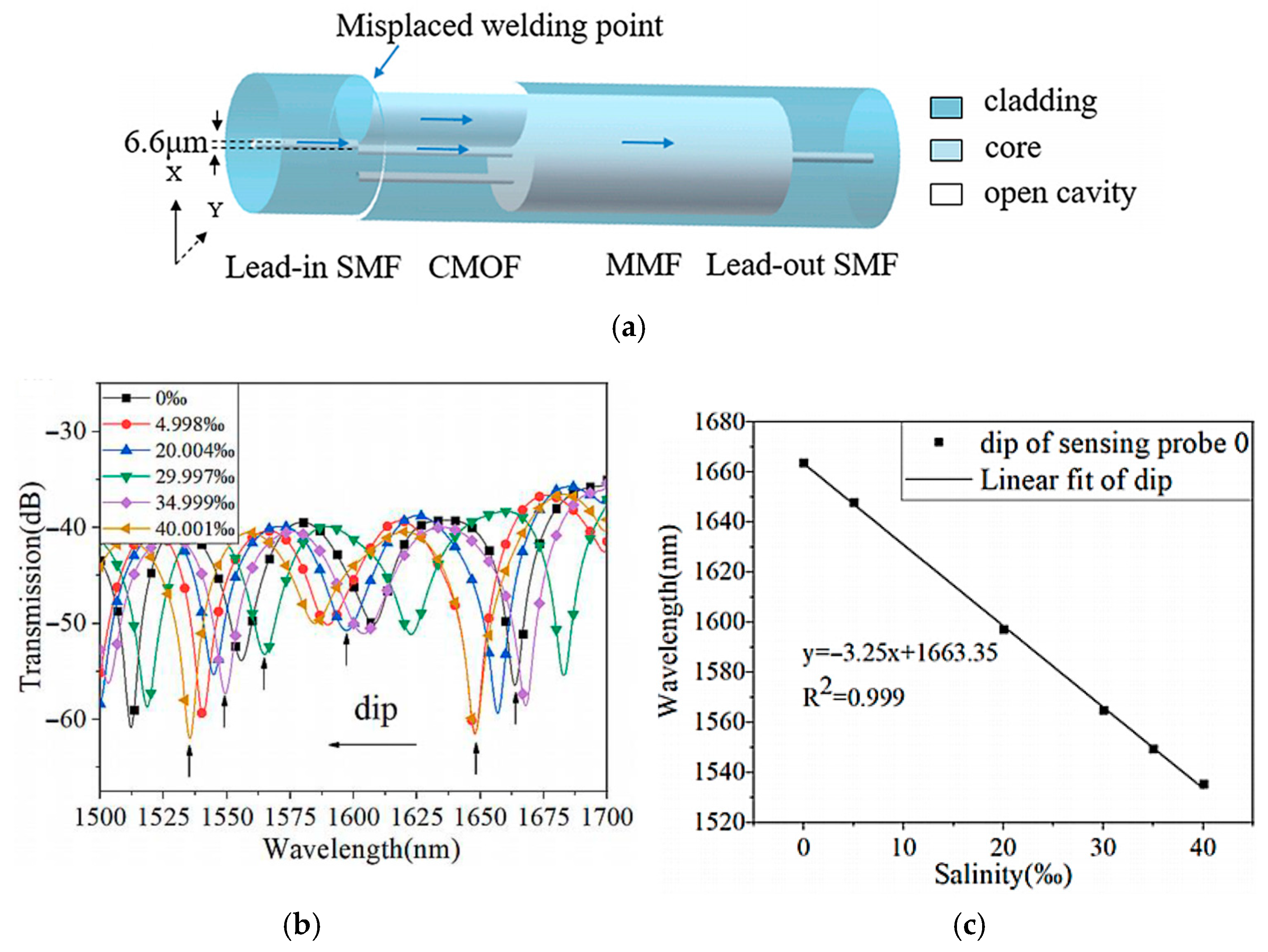
| [48] | Salinity | SMF-C-MMF-SMF | 0–40.001‰ | 3.25 nm/‰ |
| [49] | Magnetic field | SMF-C + MF-SMF | 0–7.3 mT | 0.18 nm/mT |
| [50] | Gas pressure | SMF-NCF-SCSHF-HCF | 0–100 kPa | 183 nm/MPa |
| [51] | Salinity | SMF-NCF-C-NCF-SMF | 0–36‰ | 2.664 nm/‰ |
| [55] | RI and T | SMF-ECF + FBG-SMF | RI: —— T: 24–30 °C | MZI: 794 nm/RIU FBG: 8.72 pm/°C |
| [56] | RI and T | SMF-C-SMF | RI: 1.33–1.39 T: 20–70 °C | 0.0275 rad/°C 2490 rad/RIU |
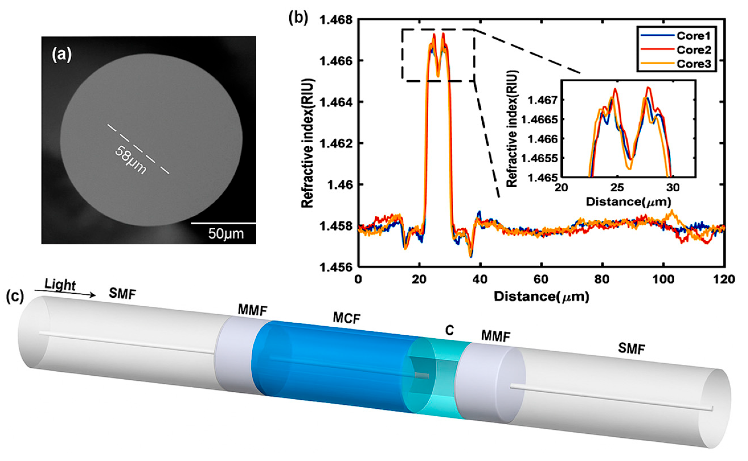
| [57] | RI | SMF-MMF-C-MMF-SMF | 1.333–1.338 | IMI: 7999.76 nm/RIU ICMI: 6211.98 nm/RIU |
| Ref. | Detection Object | Optimization Method | Measuring Range | Sensitivity |
|---|---|---|---|---|
| [68] | RI | Au-Ag | 1.33–1.42 | 16,400 nm/RIU |
| [66] | RI | SNS | 1.33–1.42 | 7903 nm/RIU |
| [69] | RI | Silver wire | 1.33–1.34 | 3000 nm/RIU |
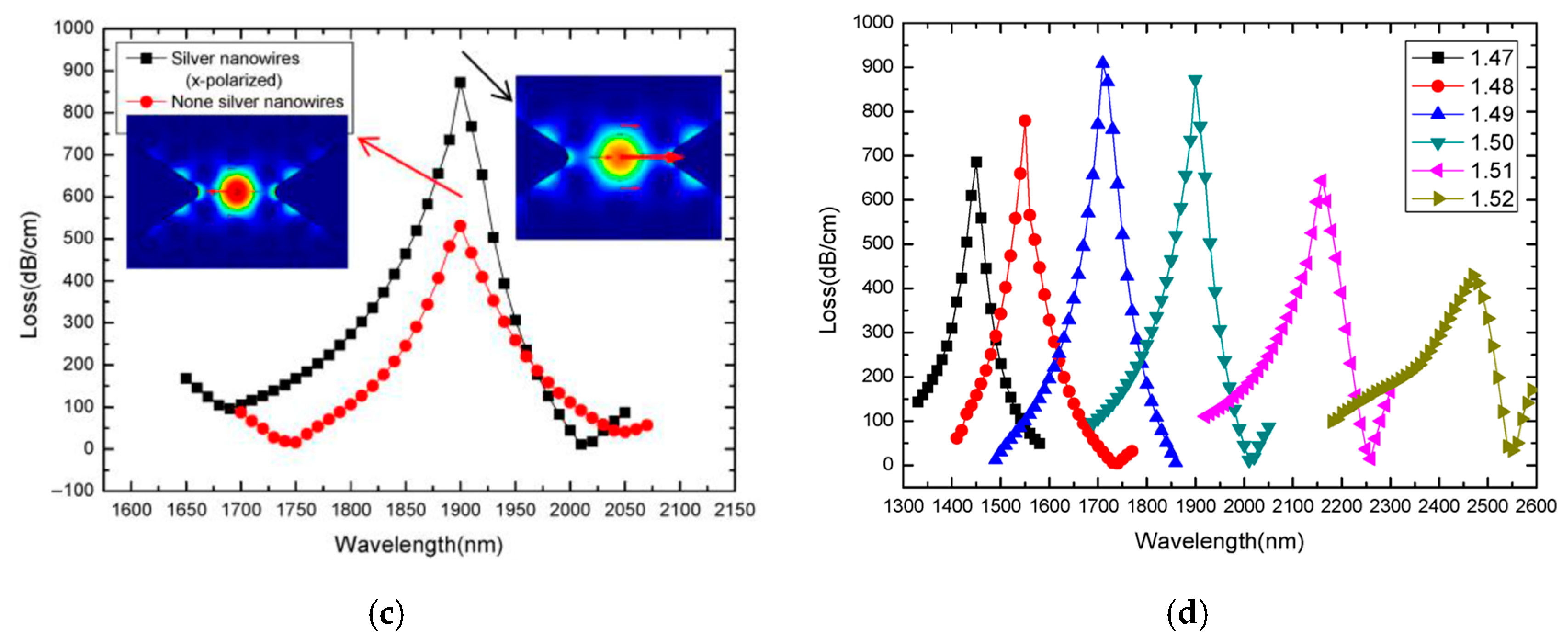
| [70] | RI | Silver nanowire | 1.47–1.52 | 31,000 nm/RIU |
| [72] | RI | MoO2 | 1.31–1.37 | 4821 nm/RIU |
| Category | Decoupling Strategy | Ref. | Structural Core | Measurement Range | Sensitivity |
|---|---|---|---|---|---|
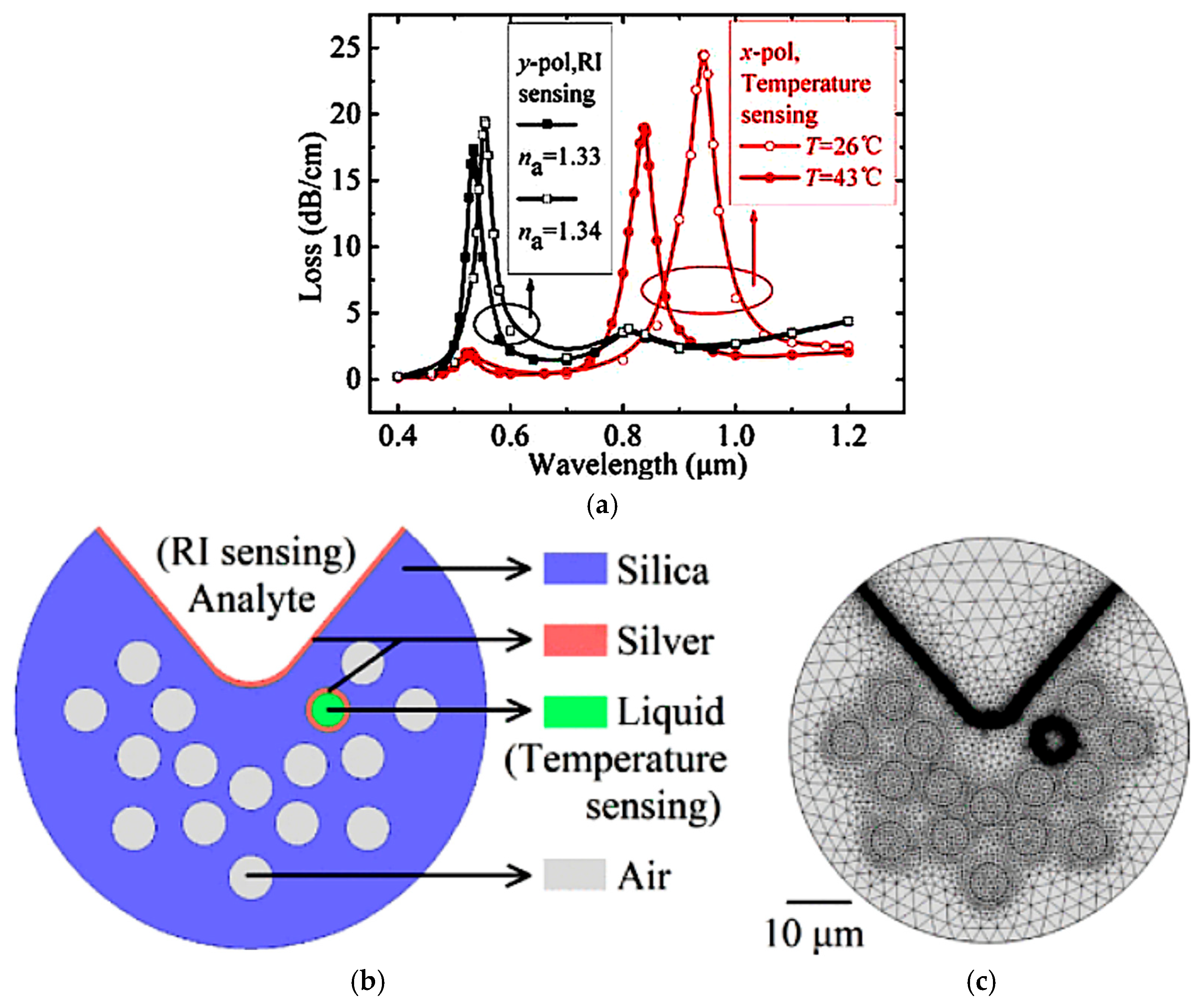
| A | A1: orthogonal polarization decoupling | [76] | metal film + thermo-sensitive liquid | 1.33~1.4 26~43 °C | 12,500 nm/RIU 6.18 nm/K |
| A2: channel function separation design | [77] | grating structure + thermo-sensitive material + distributed channel | 30‰~40‰ 5~35 °C | 1.402 nm/‰ 7.069 nm/°C | |
| [78] | 0~10 Mpa −4~35 °C | 1.709 nm/Mpa 1.054 nm/°C | |||
| B | B1: dual-peak synergistic response separation | [81] | metal film + thermo-sensitive liquid + dual channel | 0~153.32‰ 22~44 °C | 0.296 nm/‰ 2.4 nm/°C |
| [80] | 1.33~1.41 0~100 °C | 11,369 nm/RIU 3.15 nm/°C | |||
| B2: spectral peak shift control | [79] | porosity adjustment + thermo-expansive material | 0~50 °C | 19.9 nm/°C | |
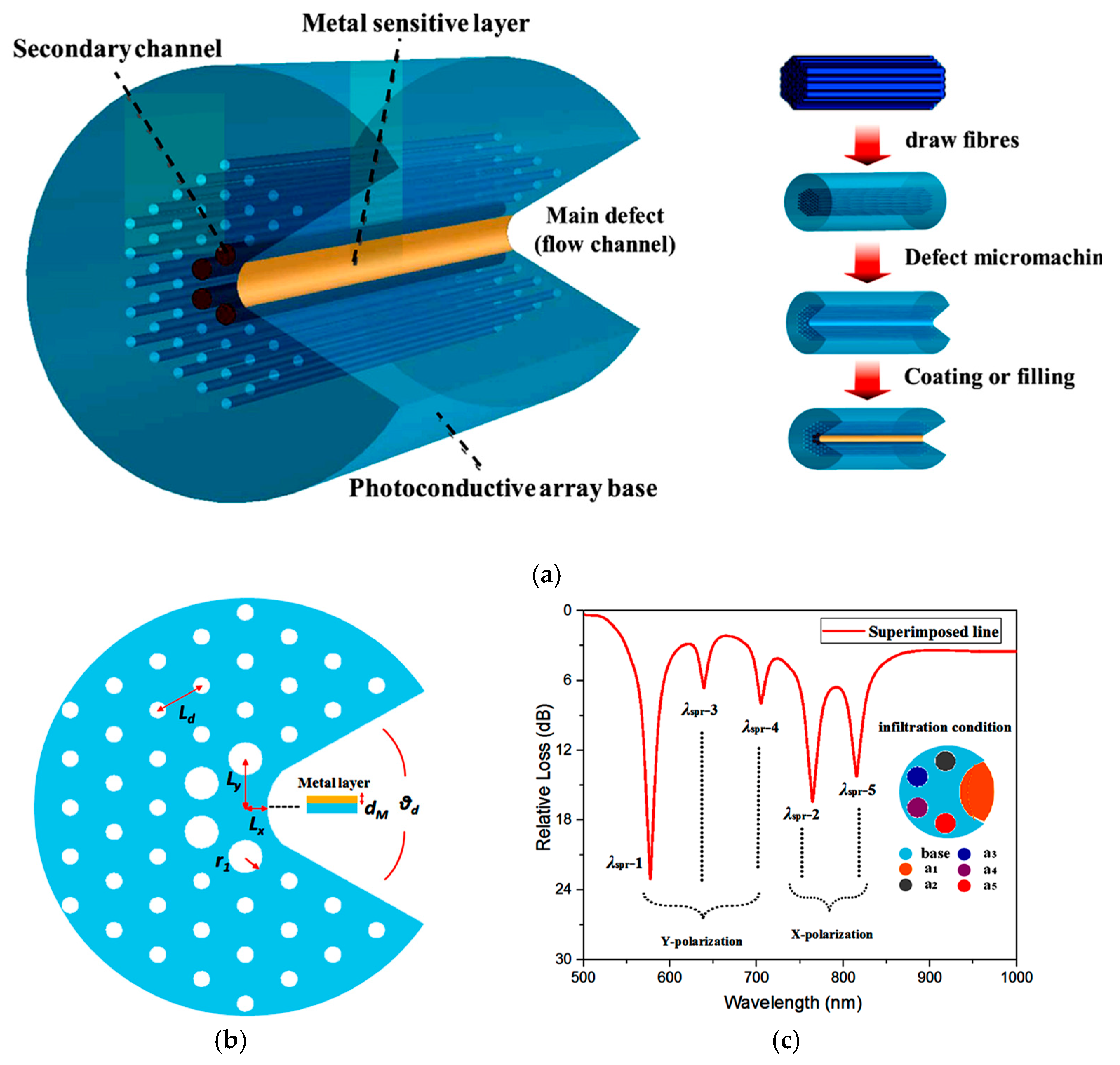
| B3: multi-dimensional multi-zone coupling | [82] | five-channel design with microstructural differences and thermo-expansive material | 1.33~1.44 | 45,322 nm/RIU |
Disclaimer/Publisher’s Note: The statements, opinions and data contained in all publications are solely those of the individual author(s) and contributor(s) and not of MDPI and/or the editor(s). MDPI and/or the editor(s) disclaim responsibility for any injury to people or property resulting from any ideas, methods, instructions or products referred to in the content. |
© 2025 by the authors. Licensee MDPI, Basel, Switzerland. This article is an open access article distributed under the terms and conditions of the Creative Commons Attribution (CC BY) license (https://creativecommons.org/licenses/by/4.0/).
Share and Cite
Gao, Z.; Li, Z.; Ying, Y. A Review of the Research Progress on Optical Fiber Sensors Based on C-Type Structures. Photonics 2025, 12, 695. https://doi.org/10.3390/photonics12070695
Gao Z, Li Z, Ying Y. A Review of the Research Progress on Optical Fiber Sensors Based on C-Type Structures. Photonics. 2025; 12(7):695. https://doi.org/10.3390/photonics12070695
Chicago/Turabian StyleGao, Zhijun, Zhenbo Li, and Yu Ying. 2025. "A Review of the Research Progress on Optical Fiber Sensors Based on C-Type Structures" Photonics 12, no. 7: 695. https://doi.org/10.3390/photonics12070695
APA StyleGao, Z., Li, Z., & Ying, Y. (2025). A Review of the Research Progress on Optical Fiber Sensors Based on C-Type Structures. Photonics, 12(7), 695. https://doi.org/10.3390/photonics12070695