Article

Collaboration of Two UV-Absorbing Dyes in Cholesteric Liquid Crystals Films for Infrared Broadband Reflection and Ultraviolet Shielding

1
School of Materials Science and Engineering, University of Science and Technology Beijing, Beijing 100083, China
2
Beijing Mechanical and Electrical Engineering Design Department, Beijing 100854, China
*
Authors to whom correspondence should be addressed.
These authors contributed equally to this work.
Photonics 2025, 12(7), 656; https://doi.org/10.3390/photonics12070656
Submission received: 30 May 2025 / Revised: 23 June 2025 / Accepted: 27 June 2025 / Published: 29 June 2025
(This article belongs to the Special Issue Liquid Crystals in Photonics II)

Abstract

This study developed cholesteric liquid crystal broadband reflective films using zinc oxide nanoparticles (ZnO NPs) and homotriazine UV-absorbing dye (UV-1577) to enhance infrared shielding. Unlike benzotriazole-based UV absorber UV-327, which suffers from volatility and contamination, UV-1577 exhibits superior compatibility with liquid crystals, higher UV absorption efficiency, and enhanced processing stability due to its larger molecular structure. By synergizing UV-1577 with ZnO NPs, we achieved a gradient UV intensity distribution across the film thickness, inducing a pitch gradient that broadened the reflection bandwidth to 915 nm and surpassing the performance of previous systems using UV-327/ZnO NPs (<900 nm). We conducted a detailed examination of the factors influencing the reflective bandwidth. These included the UV-1577/ZnO NP ratio, the concentrations of the polymerizable monomer (RM257) and chiral dopant (R5011), along with polymerization temperature, UV irradiation intensity, and irradiation time. The resultant films demonstrated efficient ultraviolet shielding via the UV-1577/ZnO NPs collaboration and infrared shielding through the induced pitch gradient. This work presents a scalable strategy for energy-saving smart windows.

1. Introduction

In cholesteric liquid crystals (CLCs), molecules exhibit a helical self-assembly where their local orientation rotates continuously along the helical axis. While schematic representations often depict this as discrete layers with a fixed rotation angle (e.g., ~15°) between them, it is important to note that this is a simplified model; the rotation is continuous in reality. This structural periodicity produces distinctive optical properties including selective Bragg reflection [1]. Pitch and helix orientation are two important parameters characterizing the helical structure of CLCs, which determine the wavelength and circular polarizability of the reflected light, respectively. The pitch is the interlayer spacing of the molecules oriented along the helical axis rotated by 360°. According to Bragg’s law (λ = np, where n is the average refractive index, and P is the helical pitch), pitch variation enables wavelength-selective reflection in CLCs. The pitch (P) is determined by the helical twisting power (HTP) and chiral dopant concentration (c), as defined by P = 1/(HTP × c). As the chiral dopant concentration increases, the helical pitch P decreases, leading to a blue shift in the reflection wavelength. For instance, De Vries [2] demonstrated that by adjusting the composition ratio of chiral components, the pitch could be continuously reduced from the micrometer scale down to sub-micrometer dimensions (e.g., 0.24 μm), enabling reflection coverage across the visible to near-infrared spectrum. This behavior is analogous to the shift of the absorption peaks toward higher frequencies observed when elevating the Fermi level in Dirac semimetals. Such a linear correlation between parameter and performance offers a universal strategy for the dynamic control of optoelectronic devices [3]. Similarly, CLCs can form through the introduction of specific chiral dopant concentrations into nematic liquid crystal mixtures [4,5,6,7]. Materials with the periodic helical structure are the most unique due to the circular polarization selectivity of their reflected wavelength [8,9,10], which can be applied to four-dimensional visual imaging, electro-optical devices, transducers, circularly polarized luminescence, and many other fields [11,12,13,14,15]. The helical direction is the direction of molecular rotation of the interlayer, which is divided into a left-handed helix and right-handed helix, thus determining the circular polarizability of the reflected light. That is, CLCs with right-handed helices reflect only right-handed circularly polarized light and vice versa. This selective design is complementary to polarization-insensitive graphene absorbers; the former strictly filters circularly polarized light through its helical orientation [16,17], while the latter achieves highly efficient absorption across a broad polarization range via symmetric structures [18]. Polarization-insensitive long-wave infrared absorbers are suitable for broadband spectral detection [18,19]. The reflected wavewidth of CLCs is determined by ∆λ = ∆nP, with ∆n representing the birefringence of the CLCs [20,21].
Current primary techniques for fabricating CLC films with broadband reflectance include layer-stacking approaches [22,23,24], photo-polymerization-induced molecular migration [25], thermally induced diffusion [26,27,28], modulation of the helical twisting power of chiral compounds [29,30,31,32], and electrically controlled methods [33]. These strategies fundamentally achieve broadband reflection by establishing a non-uniform pitch distribution within the film. This design principle, which involves expanding functional bandwidth through structural inhomogeneity, parallels approaches such as tuning TiN structural parameters (for example, maintaining a 30 nm difference between cylinder radius and circumscribed-square-hole radius [34]). Among these, the technique utilizing light-initiated molecular diffusion to generate pitch gradients has been extensively studied. Pioneered by Dutch scientist Broer’s team [35,36], their foundational work first employed a composite system comprising bifunctional chiral liquid crystalline monomers, single-functional polymerizable monomers, UV-absorbing dyes, and photo-initiators.
UV-absorbing dyes for UV protection are currently the most common field of application; they absorb high-energy UV light, performing energy conversion in the form of heat or harmless low radiation to release or consume the energy, thus preventing the degradation of polymers caused by sunlight or other man-made UV light and reducing the risk of harm to human beings. UV-absorbing dyes can be categorized into salicylates, benzophenones, benzotriazoles, and homotriazines according to their chemical structure [37]. The effects of benzophenones and benzotriazoles used in liquid crystal systems have been explored in previous studies. Schenning explored the effect by which diffusion of benzophenone (BP) could be used for broadband reflective coating formation by pretreating substrates with BP [38]. Using BP diffusion in the coating during curing, there is a difference in the acrylic polymerization reaction rate throughout the thickness of the coating, resulting in a pitch gradient. We previously investigated the use of benzotriazoles as UV-absorbing dyes for our experiments. Cholesteric liquid crystal films with broadband reflective properties were obtained by both direct addition and thermal spreading after substrate treatment, respectively, by photopolymerization under appropriate conditions. But the Δλ of the film prepared by thermal diffusion was only 604 nm [39]. We speculate that it may be due to the small molecular mass of UV-327, which is prone to volatilization through migration to the surface, easy decomposition by heat, and unstable performance. The addition of ZnO NPs can improve the disadvantage of organic UV-absorbing dyes that are unstable and prone to decomposition. Similarly, organic UV-absorbing dyes mitigate the poor dispersion of ZnO nanoparticles. After improvement, we chose the benzotriazoles UV-327 and ZnO NPs to be mixed and added directly to the liquid crystal system. ZnO NPs are the dyes that play a major absorbing role, and the Δλ of the obtained cholesteric liquid crystal films also did not reach 900 nm [40]. Therefore, ZnO NPs are still used as the main dye, and we carried out the research component of this manuscript with the homotriazine UV-1577 and ZnO NPs mixed and added directly to the liquid crystal system to prepare broadband reflective liquid crystal films. Homotriazine UV-absorbing dyes (UV-1577) have been popular UV absorbers in recent years because of their large molecular structure, higher UV-absorption efficiency, greater processing stability, and low contamination during processing compared to benzotriazoles (UV-327).
In this study, we innovatively used the popular UV-1577 as a UV-absorbing dye, which was mixed with ZnO NPs and then directly added to the liquid crystal mixing system. Utilizing ZnO NPs as primary UV absorbers, broadband reflective cholesteric films were fabricated through photo-induced molecular diffusion to form a non-uniform distribution of the pitch. The UV-absorbing components create an intensity gradient through the film thickness, inducing rapid polymerization of monomers on the near-light side. Differential diffusion between chiral dopants and polymerizable monomers generates a chiral concentration gradient. Consequently, the pitch exhibits a gradient distribution, decreasing from large to small from the near-light to the far-light side of the film. This mechanism effectively broadens the reflective band of the film. Experimental analyses verify that the organic UV-absorbing dye UV-1577 has good performance in terms of preparing broadband reflective films in combination with ZnO NPs. Scanning electron microscopy (SEM) provided validation of the bandwidth broadening mechanism. The CLC films leverage the synergistic effects of UV-1577 and ZnO NPs to achieve ultraviolet and infrared shielding. This multifunctional design demonstrates potential for smart window applications.

2. Materials and Methods

2.1. Materials

Figure 1 presents the chemical structures of all components utilized in this research. The experimental formulation incorporated nematic liquid crystal BHR32100-100 (ne = 1.752, no = 1.517, Δn = (ne − no) = 0.235; Beijing Bayi Space LCD Technology Co., Ltd., Beijing, China); chiral dopant R5011 (Shijiazhuang Chengzhi Yonghua Display Material Co., Ltd., Shijiazhuang, China); free-radical photo-initiator IRG651 (Aladdin Co., Ltd., Shanghai, China); organic UV-absorbing dye UV-1577 (98% purity; HEOWNS Co., Ltd., Tianjin, China); inorganic UV-absorbing zinc oxide nanoparticles (50 nm particle size, 30 wt% dispersion; Shanghai Yien Chemical Technology Co., Ltd., Shanghai, China); and UV-polymerizable monomer RM257 (588.6 g/mol; Beijing Bayi Space LCD Technology Co., Ltd., Beijing, China).

2.2. Measurements

Optical characterization was performed using a ultraviolet-visible-near-infrared spectrophotometer (JASCO-V570, Jasco Corporation, Tokyo, Japan), with transmission spectra acquired relative to blank cell references normalized to 100% transmittance. Generally, the reflection bandwidth (Δλ) is quantified as the bandwidth at half the height of the transmitted light peak. ZnO NPs dispersion within films was analyzed by polarized optical microscopy (POM, Olympus BX51, Olympus Corporation, Tokyo, Japan), while cross-sectional pitch gradient morphology was examined via scanning electron microscopy (SEM, Zeiss-SUPRA55, Jeol Ltd., Tokyo, Japan).

2.3. Preparation of Samples and Cells

For sample preparation, constituent materials were precisely weighed per Table 1 formulations using the electronic scale and transferred to labeled centrifuge tubes. Each CLC mixture received 1 mL organic solvent ethyl acetate, followed by vigorous vortex mixing (1 min) and ultrasonic homogenization (60 min) to ensure uniform ZnO NPs dispersion. Solvent evaporation was achieved through thermal treatment at 70 °C for 8 h in the oven. Following solvent evaporation, the tubes were removed and cooled to room temperature. All procedures preceding polymerization were conducted under light-free conditions to prevent premature photoreactions. The homogeneous mixtures were loaded into liquid crystal cells via capillary action using a curved needle. The liquid crystal cells were constructed with 40 μm polyethylene terephthalate (PET) spacers and glass substrates pre-coated with 3 wt% PVA solution. Substrates were dried and oriented by rubbing with a flannel to allow the molecules to obtain planar orientation. The samples were then polymerized under different conditions.

3. Results

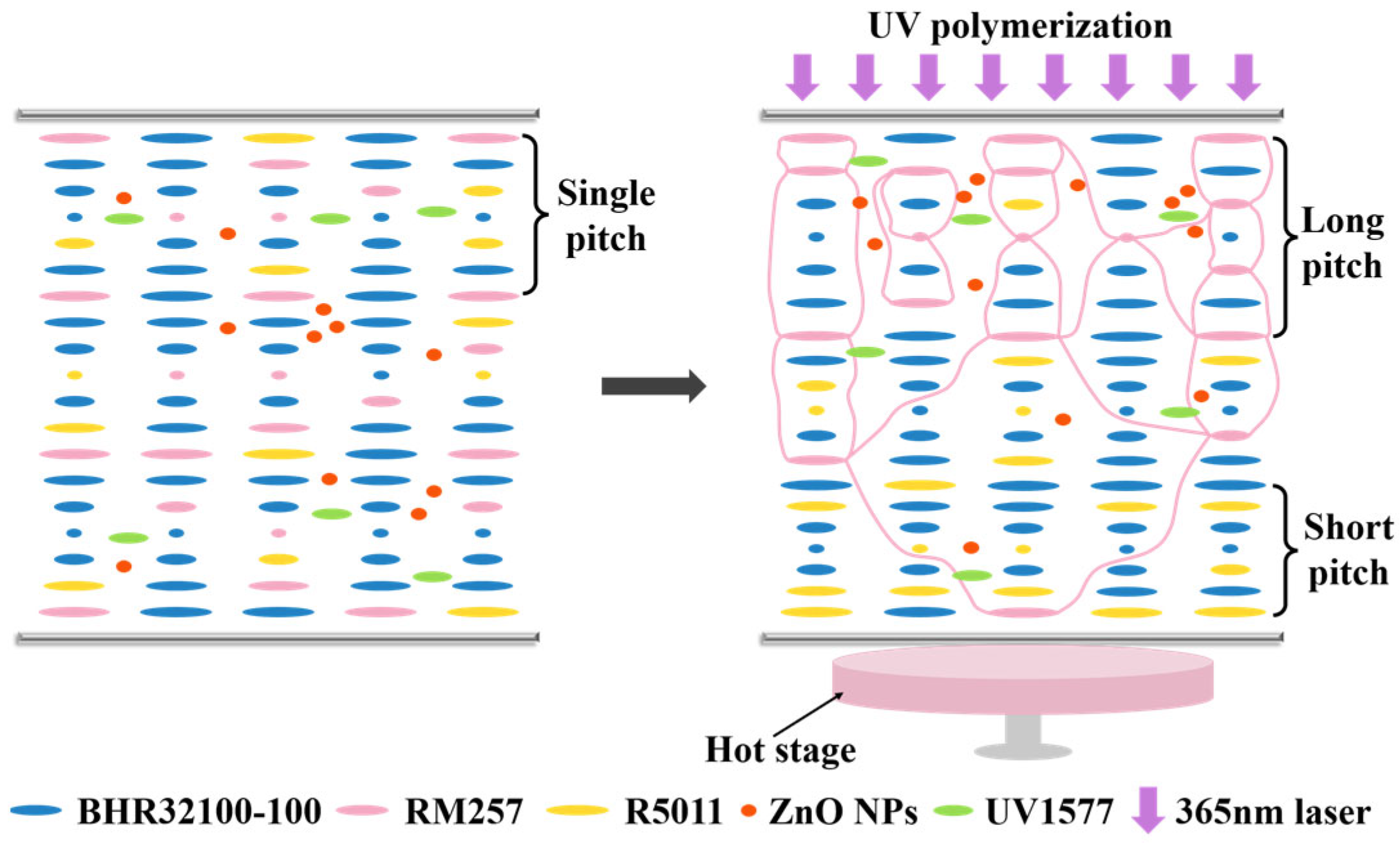
3.1. Pitch Gradient-Driven Broadband Reflection Mechanism in CLC Films

The mechanism underlying photo-induced molecular diffusion for fabricating broadband-reflective cholesteric liquid crystal films relies fundamentally on the presence of UV-absorbing dyes. ZnO NPs are semiconductor materials with strong UV absorption ability but are poorly dispersed in organic systems. UV-1577 can be better dissolved in liquid crystal mixture systems. The incorporation of UV-1577 effectively improves the disadvantage of poor dispersion and low solubility in ZnO NPs. As shown in Figure 2, the broadband reflection mechanism in this study is schematically illustrated. In liquid crystal systems (BHR32100-100, RM257, R5011, IRG651, UV-1577, and ZnO NPs), UV-1577 and ZnO NPs act together as UV-absorbing dyes. When polymerization occurs by UV irradiation, the UV-absorbing dyes are distributed in the cell with a concentration gradient along the thickness direction. The near-light side has aggregated UV-absorbing dyes, while the far-light side has the opposite, forming a UV intensity gradient in the thickness direction. RM257 is polymerized under UV irradiation and IRG651, forming a relatively dense crosslinked network. Due to the different light intensities, the polymerization rate decreases from the near-light side to the far-light side, and the trend of the monomer consumption rate is consistent with the polymerization rate. R5011, due to its non-polymerizable structure, moves toward the far-light side as RM257 diffuses toward the near-light side and is gradually anchored by the polymer network to form a chiral compound concentration gradient. R5011 has a large HTP value (115 μm−1), and the presence of a small amount of R5011 achieves the preset effect. According to P = 1/(HTP × c), the pitch gradient in the thickness direction of the film is formed in this regard, and the reflection bandwidth of the film is then obtained from ∆λ = ∆nP. The film has broadband reflection properties.

3.2. The Influence of UV-1577/ZnO NPs Mixtures on the Reflection Broadband of Samples

Across all samples within group At, the combined mass fraction of the two UV-absorbing dyes was maintained at 0.30 wt%. Specific ratios of UV-1577 and ZnO NPs were formulated as follows: 0.30/0.00 wt%, 0.24/0.06 wt%, 0.18/0.12 wt%, 0.12/0.18 wt%, 0.06/0.24 wt%, and 0.00/0.30 wt%, corresponding to samples designated At1 through At6, respectively. The proportions governing the grouping of all other samples are summarized in Table 1. Polymerization of the group At samples was conducted under ultraviolet irradiation at an intensity of 2.0 mW/cm2 for a duration of 20 min, with the temperature maintained at 50 °C. Figure 3 shows the POM photographs of the CLCs films prepared by the experimental group At after curing. It can be clearly observed that the clustering effect becomes more and more obvious as the percentage of ZnO NPs increases. The At2 and At3 samples contain fewer ZnO NPs, which can only be observed in a small number of clustered states. The effect of clustering of ZnO NPs is particularly pronounced in the films of the At5 and At6 sample groups, with At5 showing small and numerous clustered morphologies, and the largest amount of ZnO NPs in the At6 films, which appear in larger and more numerous clustered morphologies with maximum cluster sizes reaching 110 nm. Figure 4 presents the transmission spectra of experimental group At, along with the corresponding trend of Δλ with the change in the proportion of UV-absorbing dyes. As can be seen from Figure 4a, there is a significant increase in Δλ before and after curing of the film because of the presence of UV-absorbing dyes. At5 and At6 samples were too heavily clustered with the inorganic dye, resulting in a small Δλ and a significant decreasing trend. The At2 and At3 samples contain fewer ZnO NPs, and there is a clear trend of decreasing reflection bandwidth by changing the dyes ratio. Specifically, Δλ decreases from 1013 nm to 795 nm as the UV-1577 content is reduced, while the central wavelength remains essentially stable. In conclusion, the At4 sample has the best ratio of UV-absorbing dyes, the appropriate effect of nanoparticle clustering, and a relatively large reflective bandwidth of the obtained film, which secondarily aligns with the study objective of utilizing nanoparticles as the primary component of UV-absorbing dyes.

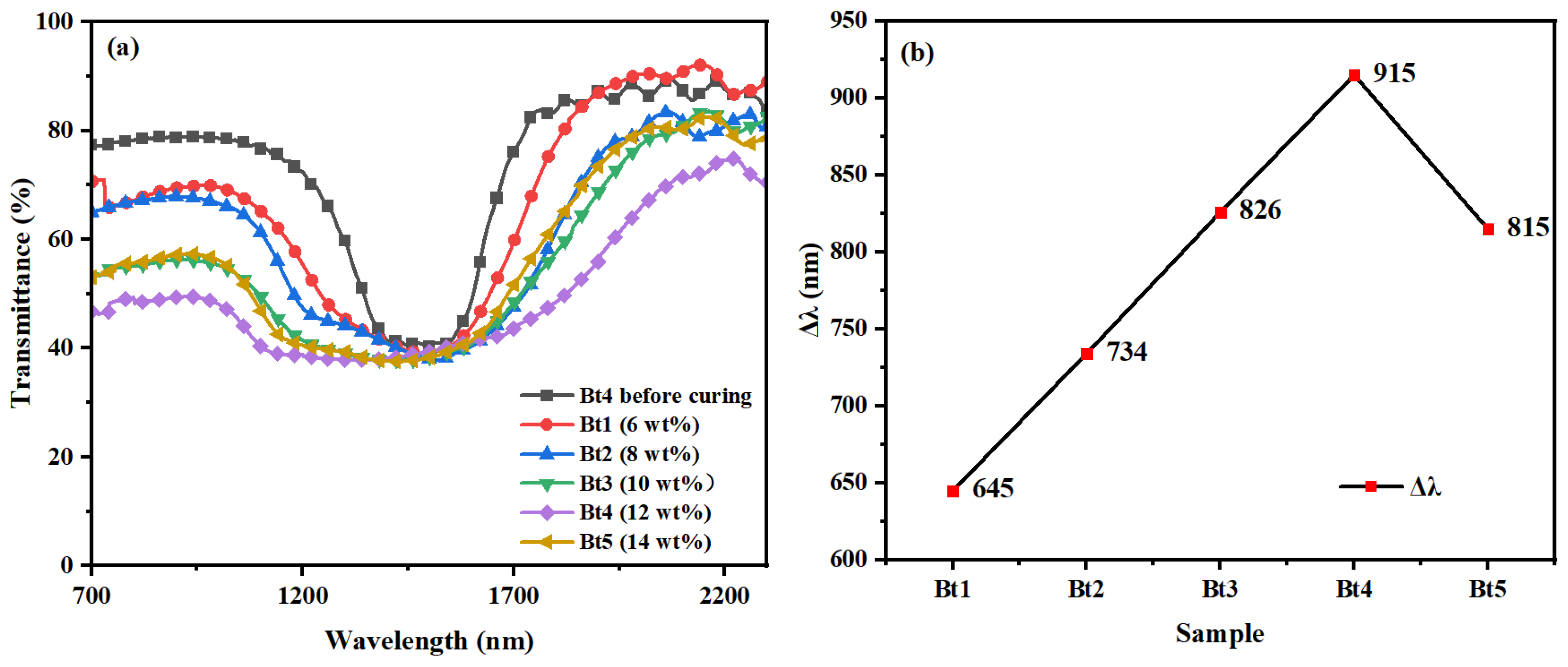
3.3. The Influence of RM257 Concentration on the Reflection Bandwidth of Samples

Figure 5 shows the POM images of the Bt group samples before and after polymerization. It is clearly seen that photopolymerization does not affect the dispersion of ZnO NPs, which maintain a consistent dispersion state across all samples with no significant changes in cluster size or distribution, and there is a good planar texture both before and after polymerization. As the content of the polymerizable monomer RM257 increases, the polymer network formed by polymerization becomes progressively tighter. Figure 6 presents the transmission spectra of experimental group Bt, along with the trend of Δλ with the change of RM257 content. Polymerization of the Bt group specimens was performed under 2.0 mW/cm2 irradiation for 20 min, with the reaction temperature maintained at 50 °C. The degree of cross-linking of the polymer network obtained after polymerization is controlled by varying the RM257 content, which affects the diffusion of molecules in the film system. When the content of RM257 increases from 6 wt% to 12 wt%, the Δλ of the film expands significantly from 645 nm to 915 nm, while the central wavelength remains nearly constant due to fixed chiral content according to Bragg’s law. This occurs because higher concentrations of the polymerizable monomer RM257 accelerate the polymerization rate, promoting migration of the chiral molecule R5011. The enhanced cross-linking density better anchors chiral molecules to form pitch gradients. However, when RM257 concentration rises further to 14 wt%, Δλ decreases to 815 nm as rapid polymerization creates an excessively dense network. This dense structure hinders the migration of unreacted monomer C6M and chiral molecule R5011, ultimately reducing the reflection bandwidth. Therefore, the samples of the Bt4 group have the best 12 wt% RM257 content, and the film obtained after curing has the largest Δλ, which can reach 915 nm.

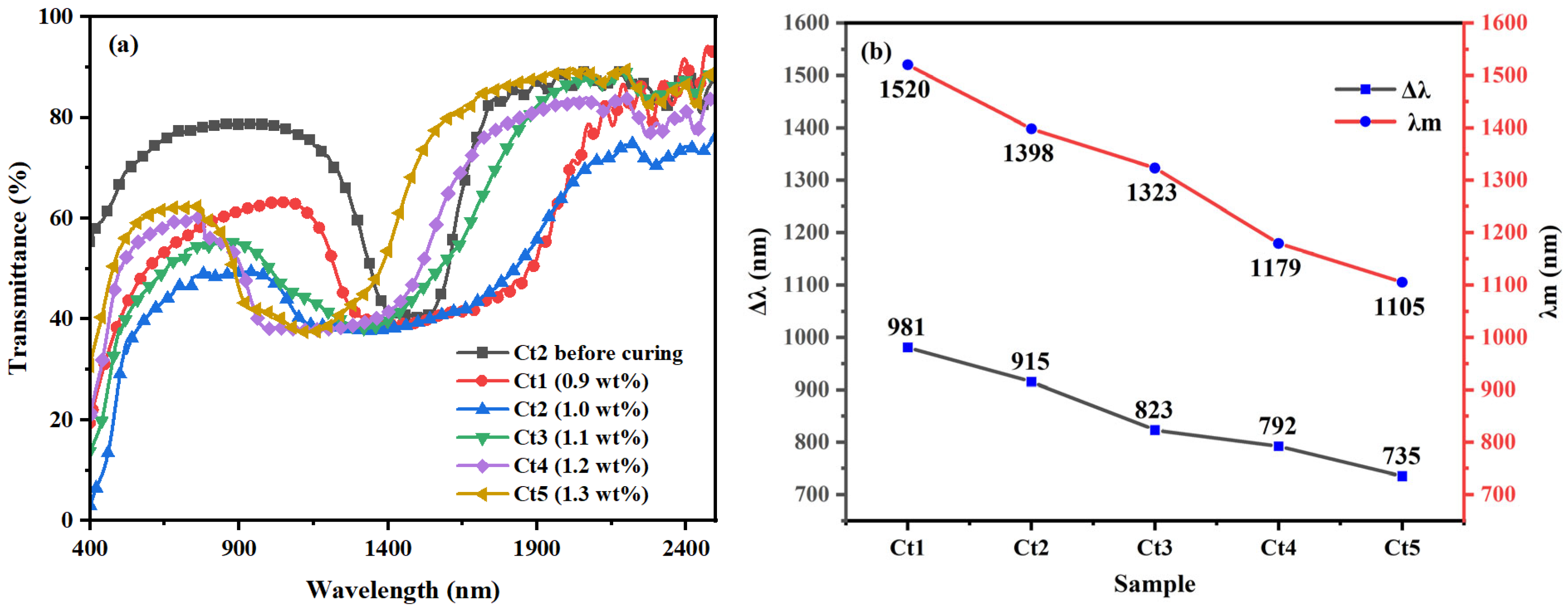
3.4. The Influence of R5011 Concentration on the Reflection Bandwidth of Samples

Figure 7 presents the transmission spectra of samples in the Ct groups and the variation trend of Δλ as the R5011 content changes. For the Ct group samples, polymerization was carried out at a light intensity of 2.0 mW/cm2 for 20 min, with the polymerization temperature maintained at 50 °C. The concentration of chiral compounds exhibits an inverse proportional relationship with the pitch, and according to the formula λ = nP, the center wavelength (λ) of the sample group (Ct1–Ct5) decreases sequentially from 1520 nm to 1105 nm. Correspondingly, the Δλ simultaneously reduces from 981 nm to 735 nm because the increase in the content of chiral compounds impairs the concentration gradient distribution effect. Ct2 was selected as the sample with the best chiral compound content according to Figure 7. This is because the center wavelength of the sample Ct2 is in the near-infrared long-wave region, which is farther away from the visible region and the near-infrared short-wave region, in addition to the relatively large reflection bandwidth.

3.5. The Influence of Polymerization Temperature on the Reflection Bandwidth of Samples

Figure 8 illustrates the transmission spectra of samples in the Dt group and the variation trend of Δλ as the polymerization temperature changes. Polymerization was conducted for 20 min at 2.0 mW/cm2, with temperatures regulated at 30 °C (Dt1), 40 °C (Dt2), 50 °C (Dt3), 60 °C (Dt4), and 70 °C (Dt5). The Δλ values initially increased from 729 nm at 30 °C to 915 nm at 50 °C, while the central wavelength remained nearly constant, then decreased to 687 nm at 70 °C. This phenomenon mainly emerges as a result of polymerization temperature intricately governing the molecular diffusion rate throughout the system. At lower temperatures, the molecular thermal motion is relatively sluggish, resulting in a slower diffusion rate. Within a fixed polymerization duration, the ideal diffusion effect cannot be attained. At higher temperatures, accelerated diffusion promotes pitch gradient formation, yet premature polymer network development compromises molecular anchoring. Consequently, the degree of molecular diffusion is enhanced, the pitch gradient is disrupted, and the Δλ of the CLC film decreases. Based on the above findings, 50 °C is identified as the optimal polymerization temperature.

3.6. The Influence of UV Intensity on the Reflection Bandwidth of Samples

Figure 9 depicts the transmission spectra and the variation trend of Δλ as a function of UV intensity for the Et group samples, which were polymerized at 50 °C for 20 min. The polymerization light intensity gradient spanned from 0.5 to 2.5 mW/cm2 across Et1–Et5 samples. As shown in Figure 9b, the maximum reflection bandwidth (Δλ = 915 nm) occurs at 2.0 mW/cm2 with a nearly constant central wavelength, while Δλ follows a non-monotonic trend of initial increase then decrease with rising UV intensity. This behavior originates from kinetic competition between polymerization and diffusion processes. Under low irradiation intensities (<2.0 mW/cm2), delayed polymer network formation fails to effectively anchor migrating chiral dopants. Conversely, excessive intensities (>2.0 mW/cm2) induce rapid curing that traps dopants prior to gradient establishment. Both regimes consequently inhibit broadband reflection development. Hence, 2.0 mW/cm2 is determined to be the optimum polymerization UV intensity.

3.7. The Influence of Polymerization Time on the Reflection Bandwidth of Samples

Figure 10 illustrates the transmission spectra of the Ft group samples and the variation trend of Δλ as the polymerization time changes. The samples of the Ft group were polymerized at 50 °C, and the light intensity was kept at 2.0 mW/cm2. The polymerization time of Ft1–Ft7 samples ranged consecutively from 3 to 30 min. During the initial 20 min of polymerization, the Δλ of the samples (Ft1–Ft5) rose from 598 nm to 915 nm, with the central wavelength remaining nearly constant. Extended UV irradiation time intensifies molecular diffusion, amplifying the diffusion-induced concentration gradient and thereby enhancing the pitch gradient within the sample. After 20 min of polymerization, Δλ stabilized near 915 nm, reaching peak reflection bandwidth. The subsequent increase in UV irradiation polymerization time (Ft6–Ft7) was continued, and the reflection bandwidth stabilized with almost no change. Because from 20 min onwards, the polymerizable monomers in the CLC system had been reacted, the polymer network was completely formed, the chiral molecules were anchored by the cured network, the pitch gradient was stabilized, and the broadband reflective characteristics of the film were formed and remained stable in this regard.

3.8. Comparison of the Optimal Samples

Figure 11a compares the transmission spectra of sample Gt1 (BHR32100-100/RM257/R5011/IRG651/UV-1577/ZnO NPs = 86.40/12.00/1.00/0.30/0.12/0.18) before polymerization and after 20 min UV irradiation at 50 °C (2.0 mW/cm2). The optimal sample achieved a broadened Δλ of 915 nm after polymerization. It is shown that the reflective bandwidth of the samples can be significantly broadened in the preparation of films by photo-induced molecular diffusion using the organic UV-absorbing dye UV-1577 doped with a liquid crystal system containing inorganic UV-absorbing dye ZnO NPs. Our previous experiments demonstrated that the reflection bandwidth of broadband reflective films prepared by the action of UV-327-assisted ZnO NPs was less than 900 nm [40]. Figure 11b shows an SEM image taken of the cross-section of the film after polymerization of the Gt1 sample, revealing distinct bright stripes corresponding to the helical pitch. It is observed that the pitch values satisfy P1 (≈1191 nm) > P2 (≈860 nm), which verifies the establishment of a pitch gradient distribution along the thickness direction of the film. This gradient structure directly results from UV-induced molecular diffusion causing non-uniform chiral dopant distribution along the thickness, which generates the observed broadband reflection.
Ultraviolet radiation, an invisible component of the electromagnetic spectrum, poses significant health risks due to its capacity to trigger photochemical reactions upon excessive exposure. Prolonged UV irradiation adversely affects human physiological functions, particularly causing damage to the skin, eyes, and immune system. Therefore, it is particularly crucial to protect against UV radiation. Leveraging the synergistic UV-absorbing properties of UV-1577 and ZnO NPs, we conducted a UV shielding test at 365 nm between the best sample Gt1 and the blank sample. As illustrated in Figure 12, under identical UV irradiation conditions, the blank sample exhibited a UV transmittance intensity of 0.979 mW/cm2 (Figure 12a), whereas the Gt1 film demonstrated a significantly reduced transmittance of 0.295 mW/cm2 (Figure 12b), corresponding to a UV shielding efficiency of 69.9%. Uthirakumar et al. [41] reported that a PMMA film containing 1 wt% CQD/N-ZnO exhibited a UV shielding efficiency of 62% at 100 μm thickness. This efficiency increased to 92% when the thickness was raised to 250 μm, which is more than six times thicker than our samples. In contrast, our system leverages the synergistic effect between UV-1577 and ZnO NPs. It demonstrates excellent UV shielding performance under relatively simple preparation conditions, without requiring complex structural design of the materials.
Energy consumption from cooling, heating, and lighting systems in buildings typically accounts for a significant proportion, making the regulation of solar near-infrared light transmission through windows a pivotal approach to reduce energy use [42,43]. It is worth emphasizing that approximately 50% of the total solar energy reaching the Earth is concentrated in the near-infrared wavelength range of 700 nm to 2500 nm [44,45]. Thus, the effective control of near-infrared light penetration through windows represents a critical strategy for achieving building thermal management and low-energy consumption [46]. For instance, shielding near-infrared light in summer can effectively mitigate the photothermal effect indoors, substantially reducing the demand for air conditioning [47]. To evaluate the infrared shielding performance of the CLC films, we constructed a testing device simulating an enclosed environment. The system employed a solar-spectrum infrared source (630 nm to 5 μm) and incorporated a temperature monitoring probe inside the simulated enclosure. Temperature variations were monitored under two conditions, including the blank group and the best sample Gt1. During the 10 min infrared irradiation period, the blank group exhibited a temperature rise from 27.2 °C to 55.3 °C (ΔT = +28.1 °C, Figure 13a), whereas the best sample Gt1 increased from 27.2 °C to 48.2 °C (ΔT = +21.0 °C, Figure 13b). This 25.3% reduction in temperature rise conclusively demonstrates that integrating the broadband reflective CLC film as the smart window application film mitigates indoor temperature rise.

4. Conclusions

In conclusion, we developed a synergistic approach using organic UV-1577 and inorganic ZnO nanoparticles as the UV-absorbing dyes to fabricate cholesteric liquid crystal films with broadband reflective properties. Through photo-induced molecular diffusion to generate pitch gradient, the broadband reflection effect of the film is remarkable, and the Δλ of the film reaches 915 nm. This strategy overcomes the dispersion challenges of ZnO NPs in organic matrices while achieving enhanced compatibility between UV-1577 and ZnO NPs compared to prior systems. Comprehensive parameter optimization established ideal conditions for polymerizable monomer RM257, chiral dopant R5011, UV-absorbing dyes radio, polymerization temperature, UV intensity, and irradiation time. Polarization microscopy, UV transmission spectroscopy, and scanning electron microscopy proved the validity of our proposed principle. Additionally, UV-shielding experiments confirmed the effective attenuation of harmful ultraviolet radiation through the synergistic interaction between UV-1577 and ZnO NPs. The simulated infrared shielding experiments confirmed that the CLC films exhibit superior broadband reflection in the infrared region. Although cross-linked acrylate networks ensure structural stability under laboratory conditions, industrial scalability and material cost efficiency remain to be optimized. Future work will focus on developing continuous fabrication processes and alternative monomers to address these limitations. These findings underscore their potential for applications in energy-efficient smart windows, particularly in architectural design, to effectively reduce energy loss caused by solar heat absorption. We believe that this research on broadband reflective films will lead to a wider range of applications in energy-efficient buildings, smart glazing systems, or functional coatings.

Author Contributions

Conceptualization, M.X. and Y.L.; methodology, X.Z.; software, M.X. and Y.L.; validation, M.X., Y.L., X.Z., and Z.L.; formal analysis, M.X. and Y.L.; investigation, X.Z.; resources, M.X. and Y.L.; data curation, M.X., Y.L., and X.Z.; writing—original draft preparation, M.X., Y.L., and X.Z.; writing—review and editing, M.X., Y.L., and G.C.; visualization, M.X., Y.L., X.Z., Z.L., J.Z., D.Z., and M.L.; supervision, H.C., G.C., and M.L.; project administration, H.C.; funding acquisition, H.C. All authors have read and agreed to the published version of the manuscript.

Funding

This research was funded by the State Key Laboratory for Advanced Metals and Materials (No. 2018Z-06).

Institutional Review Board Statement

Not applicable.

Informed Consent Statement

Not applicable.

Data Availability Statement

Data are contained within the article.

Conflicts of Interest

The authors declare no conflicts of interest.

Abbreviations

The following abbreviations are used in this manuscript:
ZnO NPszinc oxide nanoparticles
CLCcholesteric liquid crystal
BPbenzophenone
POMpolarized light microscopy
SEMscanning electron microscopy
PETpolyethylene terephthalate

References

  1. Berreman, D.W.; Scheffer, T.J. Bragg reflection of light from single-domain cholesteric liquid-crystal films. Phys. Rev. Lett. 1970, 25, 577–580. [Google Scholar] [CrossRef]
  2. De Vries, H. Rotatory power and other optical properties of certain liquid crystals. Acta Crystallogr. 1951, 4, 219–226. [Google Scholar] [CrossRef]
  3. Cheng, S.; Li, W.; Zhang, H.; Akhtar, M.N.; Yi, Z.; Zeng, Q.; Ma, C.; Sun, T.; Wu, P.; Ahmad, S. High sensitivity five band tunable metamaterial absorption device based on block like Dirac semimetals. Opt. Commun. 2024, 569, 130816. [Google Scholar] [CrossRef]
  4. Broer, D.J.; Lub, J.; Mol, G.N. Wide-band reflective polarizers from cholesteric polymer networks with a pitch gradient. Nature 1995, 378, 467–469. [Google Scholar] [CrossRef]
  5. Zheng, Z.-g.; Wang, C.; Shen, D. Dichroic-dye-doped polymer stabilized optically isotropic chiral liquid crystals. J. Mater. Chem. C 2013, 1, 6471–6478. [Google Scholar] [CrossRef]
  6. Mitov, M. Cholesteric Liquid Crystals with a Broad Light Reflection Band. Adv. Mater. 2012, 24, 6260–6276. [Google Scholar] [CrossRef] [PubMed]
  7. Zheng, Z.-g.; Liu, B.-w.; Zhou, L.; Wang, W.; Hu, W.; Shen, D. Wide tunable lasing in photoresponsive chiral liquid crystal emulsion. J. Mater. Chem. C 2015, 3, 2462–2470. [Google Scholar] [CrossRef]
  8. Zheng, Z.-G.; Lu, Y.-Q.; Li, Q. Photoprogrammable mesogenic soft helical architectures: A promising avenue toward future chiro-optics. Adv. Mater. 2020, 32, 1905318. [Google Scholar] [CrossRef]
  9. Dai, L.; Li, W.; Cao, J.; Li, J.; Liu, S. Formation, tuning and application of chiral nematic liquid crystal phase based on nanocrystalline cellulose. Prog. Chem. 2015, 27, 861–869. [Google Scholar] [CrossRef]
  10. He, Y.; Lin, S.; Guo, J.; Li, Q. Circularly polarized luminescent self-organized helical superstructures: From materials and stimulus-responsiveness to applications. Aggregate 2021, 2, e141. [Google Scholar] [CrossRef]
  11. Ma, L.-L.; Wu, S.-B.; Hu, W.; Liu, C.; Chen, P.; Qian, H.; Wang, Y.; Chi, L.; Lu, Y.-Q. Self-assembled asymmetric microlenses for four-dimensional visual imaging. ACS Nano 2019, 13, 13709–13715. [Google Scholar] [CrossRef]
  12. Schmidtke, J.; Juennemann, G.; Keuker-Baumann, S.; Kitzerow, H.-S. Electrical fine tuning of liquid crystal lasers. Appl. Phys. Lett. 2012, 101, 051117. [Google Scholar] [CrossRef]
  13. Palto, S.P.; Shtykov, N.M.; Umanskii, B.A.; Barnik, M.I. Multiwave out-of-normal band-edge lasing in cholesteric liquid crystals. J. Appl. Phys. 2012, 112, 013105. [Google Scholar] [CrossRef]
  14. Davies, D.J.D.; Vaccaro, A.R.; Morris, S.M.; Herzer, N.; Schenning, A.P.H.J.; Bastiaansen, C.W.M. A Printable optical time-temperature integrator based on shape memory in a chiral nematic polymer network. Adv. Funct. Mater. 2013, 23, 2723–2727. [Google Scholar] [CrossRef]
  15. Lin, S.; Tang, Y.; Kang, W.; Bisoyi, H.K.; Guo, J.; Li, Q. Photo-triggered full-color circularly polarized luminescence based on photonic capsules for multilevel information encryption. Nat. Commun. 2023, 14, 3005. [Google Scholar] [CrossRef]
  16. Mitov, M.; Dessaud, N. Going beyond the reflectance limit of cholesteric liquid crystals. Nat. Mater. 2006, 5, 361–364. [Google Scholar] [CrossRef]
  17. Guillard, H.; Sixou, P. Active broadband polymer stabilized liquid crystals. Liq. Cryst. 2001, 28, 933–944. [Google Scholar] [CrossRef]
  18. Ai, Z.; Liu, H.; Cheng, S.; Zhang, H.; Yi, Z.; Zeng, Q.; Wu, P.; Zhang, J.; Tang, C.; Hao, Z. Four peak and high angle tilted insensitive surface plasmon resonance graphene absorber based on circular etching square window. J. Phys. D Appl. Phys. 2025, 58, 185305. [Google Scholar] [CrossRef]
  19. Wang, J.; Yang, H.; Yi, Z.; Wang, J.; Cheng, S.; Li, B.; Wu, P. High absorption broadband ultra-long infrared absorption device based on Nanoring-Nanowire metasurface structure. Photonics 2025, 12, 451. [Google Scholar] [CrossRef]
  20. Li, Y.; Liu, Y.; Luo, D. Optical thermal sensor based on cholesteric film refilled with mixture of toluene and ethanol. Opt. Eng. 2017, 25, 26349–26355. [Google Scholar] [CrossRef]
  21. Wu, P.-C.; Wu, G.-W.; Timofeev, I.V.; Zyryanov, V.Y.; Lee, W. Electro-thermally tunable reflective colors in a self-organized cholesteric helical superstructure. Photonics Res. 2018, 6, 1094–1100. [Google Scholar] [CrossRef]
  22. Huang, Y.; Zhou, Y.; Wu, S.-T. Broadband circular polarizer using stacked chiral polymer films. Opt. Eng. 2007, 15, 6414–6419. [Google Scholar] [CrossRef]
  23. Kralik, J.C.; Fan, B.; Vithana, H.; Li, L.; Faris, S.M. Backlight output enhancement using cholesteric liquid crystal films. Mol. Cryst. Liq. Cryst. Sci. Technol. Sect. A-Mol. Cryst. Liq. Cryst. 1997, 301, 249–254. [Google Scholar] [CrossRef]
  24. Li, Y.-C.; Lin, B.-H.; Neyts, K.; Beeckman, J.; Wang, C.-T. Multiband reflectors based on stacked single-pitch cholesteric liquid crystal films. Opt. Laser Technol. 2025, 190, 113290. [Google Scholar] [CrossRef]
  25. Relaix, S.; Bourgerette, C.; Mitov, M. Broadband reflective liquid crystalline gels due to the ultraviolet light screening made by the liquid crystal. Appl. Phys. Lett. 2006, 89, 251907. [Google Scholar] [CrossRef]
  26. Sixou, P.; Gautier, C. Passive broadband reflector using photocrosslinkable liquid crystal molecules. Polym. Adv. Technol. 2002, 13, 329–338. [Google Scholar] [CrossRef]
  27. Xiao, J.; Cao, H.; He, W.; Ma, Z.; Geng, J.; Wang, L.; Wang, G.; Yang, H. Wide-band reflective polarizers from cholesteric liquid crystals with stable optical properties. J. Appl. Polym. Sci. 2007, 105, 2973–2977. [Google Scholar] [CrossRef]
  28. Guo, J.; Sun, J.; Zhang, L.; Li, K.; Cao, H.; Yang, H.; Zhu, S. Broadband reflection in polymer stabilized cholesteric liquid crystal cells with chiral monomers derived from cholesterol. Polym. Adv. Technol. 2008, 19, 1504–1512. [Google Scholar] [CrossRef]
  29. Wang, Y.; Li, Q. Light-driven chiral molecular switches or motors in liquid crystals. Adv. Mater. 2012, 24, 1926–1945. [Google Scholar] [CrossRef]
  30. Xiang, J.; Li, Y.; Li, Q.; Paterson, D.A.; Storey, J.M.D.; Imrie, C.T.; Lavrentovich, O.D. Electrically tunable selective reflection of light from ultraviolet to visible and infrared by heliconical cholesterics. Adv. Mater. 2015, 27, 3014–3018. [Google Scholar] [CrossRef]
  31. Bisoyi, H.K.; Li, Q. Light-driven liquid crystalline materials: From photo -induced phase transitions and property modulations to applications. Chem. Rev. 2016, 116, 15089–15166. [Google Scholar] [CrossRef]
  32. Bisoyi, H.K.; Bunning, T.J.; Li, Q. Stimuli-driven control of the helical axis of self-organized soft helical superstructures. Adv. Mater. 2018, 30, 1706512. [Google Scholar] [CrossRef] [PubMed]
  33. Hu, W.; Zhao, H.; Song, L.; Yang, Z.; Cao, H.; Cheng, Z.; Liu, Q.; Yang, H. Electrically controllable selective reflection of chiral nematic liquid crystal/chiral ionic liquid composites. Adv. Mater. 2010, 22, 468–472. [Google Scholar] [CrossRef]
  34. Liu, H.; Li, J.; Yang, H.; Wang, J.; Li, B.; Zhang, H.; Yi, Y. TiN-Only metasurface absorber for solar energy harvesting. Photonics 2025, 12, 443. [Google Scholar] [CrossRef]
  35. Rosenhauer, R.; Fischer, T.; Stumpe, J.; Giminez, R.; Pinol, M.; Serrano, J.-L.; Broer, D.J. Light-induced orientation of dyes in azobenzene containing LC polymers. In Liquid Crystals VI; SPIE: Pune, India, 2002; pp. 121–135. [Google Scholar] [CrossRef]
  36. Broer, D.J. On the history of reactive mesogens: Interview with Dirk J. Broer. Adv. Mater. 2020, 32, 1905144. [Google Scholar] [CrossRef]
  37. Chisvert, A.; Benede, J.L.; Salvador, A. Current trends on the determination of organic UV filters in environmental water samples based on microextraction techniques—A review. Anal. Chim. Acta 2018, 1034, 22–38. [Google Scholar] [CrossRef]
  38. van Heeswijk, E.P.A.; Kloos, J.J.H.; de Heer, J.; Hoeks, T.; Grossiord, N.; Schenning, A.P.H.J. Well-adhering, easily producible photonic reflective coatings for plastic substrates. ACS Appl. Mater. Interfaces 2018, 10, 30008–30013. [Google Scholar] [CrossRef] [PubMed]
  39. Han, R.; Gan, P.; Zhang, X.; Shi, W.; Li, H.; Cao, H.; Wang, H.; Wang, D.; Yang, Z.; He, W. Optical properties of broadband reflection of cholesteric liquid crystal by thermal diffusion of benzotriazoles. Appl. Opt. 2022, 61, 4486–4493. [Google Scholar] [CrossRef]
  40. Zhao, X.; Liu, Y.; Cao, Y.; Cao, H.; Wang, H.; Yang, Z.; Wang, D.; He, W. Near-infrared reflective polymer films based on UV-327-doped zinc oxide nanoparticles. Materials 2023, 16, 7660. [Google Scholar] [CrossRef]
  41. Uthirakumar, P.; Devendiran, M.; Yun, J.-H.; Kim, G.C.; Kalaiarasan, S.; Lee, I.-H. Role of carbon quantum dots and film thickness on enhanced UV shielding capability of flexible polymer film containing carbon quantum dots/N-doped ZnO nanoparticles. Opt. Mater. 2018, 84, 771–777. [Google Scholar] [CrossRef]
  42. Ke, Y.; Chen, J.; Lin, G.; Wang, S.; Zhou, Y.; Yin, J.; Lee, P.S.; Long, Y. Smart Windows: Electro-, thermo-, mechano-, photochromics, and beyond. Adv. Energy Mater. 2019, 9, 1902066. [Google Scholar] [CrossRef]
  43. Wang, S.; Gao, W.; Hu, X.; Shen, Y.; Wang, L. Supramolecular strategy for smart windows. Chem. Commun. 2019, 55, 4137–4149. [Google Scholar] [CrossRef] [PubMed]
  44. Wang, Y.; Runnerstrom, E.L.; Milliron, D.J. Switchable materials for smart windows. Annu. Rev. Chem. Biomol. Eng. 2016, 7, 283–304. [Google Scholar] [CrossRef] [PubMed]
  45. Khandelwal, H.; Loonen, R.; Hensen, J.L.M.; Schenning, A.; Debije, M.G. Application of broadband infrared reflector based on cholesteric liquid crystal polymer bilayer film to windows and its impact on reducing the energy consumption in buildings. J. Mater. Chem. A 2014, 2, 14622–14627. [Google Scholar] [CrossRef]
  46. DeForest, N.; Shehabi, A.; O’Donnell, J.; Garcia, G.; Greenblatt, J.; Lee, E.S.; Selkowitz, S.; Milliron, D.J. United States energy and CO2 savings potential from deployment of near-infrared electrochromic window glazings. Build. Environ. 2015, 89, 107–117. [Google Scholar] [CrossRef]
  47. Nundy, S.; Mesloub, A.; Alsolami, B.M.; Ghosh, A. Electrically actuated visible and near-infrared regulating switchable smart window for energy positive building: A review. J. Clean. Prod. 2021, 301, 126854. [Google Scholar] [CrossRef]
Figure 1. The chemical structure of experimental materials.
Photonics 12 00656 g001
Figure 2. Schematic of the reflection bandwidth broadening mechanism.
Photonics 12 00656 g002
Figure 3. POM images (scale bars: 400 μm) of At group samples after curing at 2.0 mW/cm2 light intensity for 20 min.
Photonics 12 00656 g003
Figure 4. Group At samples: variation of (a) transmission spectra and (b) Δλ with UV-absorbing dyes mass fraction.
Photonics 12 00656 g004
Figure 5. POM images (scale bars: 400 μm) of Bt group samples before and after curing at 2.0 mW/cm2 light intensity for 20 min.
Photonics 12 00656 g005
Figure 6. Group Bt samples: variation of (a) transmission spectra and (b) Δλ with RM257 mass fraction.
Photonics 12 00656 g006
Figure 7. Group Ct samples: variation of (a) transmission spectra and (b) Δλ and λm with R5011 mass fraction.
Photonics 12 00656 g007
Figure 8. Group Dt samples: variation of (a) transmission spectra and (b) Δλ with polymerization temperature.
Photonics 12 00656 g008
Figure 9. Group Et samples: variation of (a) transmission spectra and (b) Δλ with UV intensity.
Photonics 12 00656 g009
Figure 10. Group Ft samples: variation of (a) transmission spectra and (b) Δλ with polymerization time.
Photonics 12 00656 g010
Figure 11. Optimal sample Gt1: (a) transmission spectra and (b) SEM image after curing (arrows indicate helical pitch).
Photonics 12 00656 g011
Figure 12. UV shielding test (a) the blank sample and (b) optimal sample Gt1.
Photonics 12 00656 g012
Figure 13. Infrared shielding test of samples: (a) schematic diagram, (b) temperature of the blank sample before irradiation, (c) temperature of the best sample Gt1 before irradiation, (d) temperature of the blank sample after 10 min irradiation, and (e) temperature of the best sample Gt1 after 10 min irradiation.
Photonics 12 00656 g013
Table 1. Sample group compositions and polymerization parameters.
Sample
Number
BHR32100-100/RM257/R5011/
IRG651/UV-1577/ZnO NPs
(wt%)
Polymerization Temperature
(°C)
UV Intensity
(mW/cm2)
Polymerization Time
(min)
At186.40/12.00/1.00/0.30/0.30/0.00 a502.020
At286.40/12.00/1.00/0.30/0.24/0.06502.020
At386.40/12.00/1.00/0.30/0.18/0.12502.020
At486.40/12.00/1.00/0.30/0.12/0.18502.020
At586.40/12.00/1.00/0.30/0.06/0.24502.020
At686.40/12.00/1.00/0.30/0.00/0.30502.020
Bt192.40/6.00/1.00/0.30/0.12/0.18502.020
Bt290.40/8.00/1.00/0.30/0.12/0.18502.020
Bt388.40/10.00/1.00/0.30/0.12/0.18502.020
Bt486.40/12.00/1.00/0.30/0.12/0.18502.020
Bt584.40/14.00/1.00/0.30/0.12/0.18502.020
Ct186.50/12.00/0.90/0.30/0.12/0.18502.020
Ct286.40/12.00/1.00/0.30/0.12/0.18502.020
Ct386.30/12.00/1.10/0.30/0.12/0.18502.020
Ct486.20/12.00/1.20/0.30/0.12/0.18502.020
Ct586.10/12.00/1.30/0.30/0.12/0.18502.020
Dt186.40/12.00/1.00/0.30/0.12/0.18302.020
Dt286.40/12.00/1.00/0.30/0.12/0.18402.020
Dt386.40/12.00/1.00/0.30/0.12/0.18502.020
Dt486.40/12.00/1.00/0.30/0.12/0.18602.020
Dt586.40/12.00/1.00/0.30/0.12/0.18702.020
Et186.40/12.00/1.00/0.30/0.12/0.18500.520
Et286.40/12.00/1.00/0.30/0.12/0.18501.020
Et386.40/12.00/1.00/0.30/0.12/0.18501.520
Et486.40/12.00/1.00/0.30/0.12/0.18502.020
Et586.40/12.00/1.00/0.30/0.12/0.18502.520
Ft186.40/12.00/1.00/0.30/0.12/0.18502.03
Ft286.40/12.00/1.00/0.30/0.12/0.18502.06
Ft386.40/12.00/1.00/0.30/0.12/0.18502.010
Ft486.40/12.00/1.00/0.30/0.12/0.18502.015
Ft586.40/12.00/1.00/0.30/0.12/0.18502.020
Ft686.40/12.00/1.00/0.30/0.12/0.18502.025
Ft786.40/12.00/1.00/0.30/0.12/0.18502.030
Gt186.40/12.00/1.00/0.30/0.12/0.18502.020
Note: (a) Bold entries denote varied parameters.
Disclaimer/Publisher’s Note: The statements, opinions and data contained in all publications are solely those of the individual author(s) and contributor(s) and not of MDPI and/or the editor(s). MDPI and/or the editor(s) disclaim responsibility for any injury to people or property resulting from any ideas, methods, instructions or products referred to in the content.

