Abstract
A double-sided telecentric zoom optical system can ensure the measurement and detection accuracy for different workpiece sizes and plays a crucial role in industrial detection. The conventional double-sided telecentric mechanical zoom system is faced with the problem of complex structure and difficult focusing. To address these issues, a liquid lens is applied to design a non-displacement double-sided telecentric zoom system in this paper. Here, the design method of the conventional double telecentric zoom system is analyzed first; then, the liquid lenses are substituted for the mechanical motion groups. Finally, a double-sided telecentric zoom system with a detection range of 25~60 mm and a magnification of −0.44×~−0.183× has been designed and optimized by Zemax software. The design results show that in the process of magnification, the root mean square radius of the diffuse spot in the system is smaller than the pixel size during the process of zooming. The modulation transfer function values at the Nyquist frequency of 80 lp/mm are all above 0.4, distortion is controlled within 0.2, and telecentricity is less than 0.5°, indicating that the system has excellent imaging quality, low distortion, and high telecentric and other characteristics, which meet system requirements. The design method proposed in this paper can provide an effective solution for the rapid conversion of displacement zoom systems to non-displacement zoom systems.
1. Introduction
Telecentric lenses significantly mitigate the impact of parallax and distortion caused by conventional lenses on measurement accuracy, thereby substantially enhancing precision in both measurement and inspection processes. Consequently, they have been widely adopted in fields such as machine vision inspection, semiconductor lithography, and microscopic imaging [1,2,3]. Telecentric systems are mainly divided into three types: the object telecentric system, the image telecentric system, and the double-sided telecentric system. The aperture of the object telecentric system is located on the image focal plane, making the chief rays parallel to the optical axis in the object space. Therefore, the magnification is constant, regardless of the object position. On the contrary, the aperture of the image telecentric system is located on the object focal plane, making the chief rays parallel to the optical axis in the image space, thereby ensuring that the size of the image remains unchanged and independent of the image position. The double-sided telecentric system combines the advantages of the object telecentric system and the image telecentric system and can achieve better illumination uniformity and greater depth of field, with greater advantages in industrial detection [4].
In industrial detection, different types and sizes of workpieces require different detection accuracies. When employing a double-sided telecentric with single magnification, the replacement and realignment with different magnifications lenses are required for detecting various workpieces. However, this approach not only restricts the applications but also significantly reduces detection efficiency and alignment accuracy. If the zoom system is integrated with the double-sided telecentric system, it would not only substantially enhance the cost-effectiveness of manufacturing but also significantly broaden its range of application scenarios, thereby exhibiting greater competitiveness in the market. Currently, there is a limited amount of research on double-sided telecentric zoom optical systems, with most existing studies relying on the movement of mechanical components to achieve zoom functionality [5,6,7,8,9,10,11,12]. Several researchers have proposed calculation methods for the paraxial design parameters of double-sided telecentric zoom lenses with three components or four components, providing a theoretical basis for designing such systems. For instance, J. Zhang et al. presented a systematic approach for the aberration design of a four-component double-sided telecentric zoom lens system [9]. W. Ye et al. designed a continuously variable double telecentric optical system and analyzed two methods for solving cam curves [10]. Z. Fan et al. proposed a design method based on particle swarm optimization (PSO) to automatically search for the optimal initial design of a double-sided telecentric zoom system, significantly enhancing the efficiency of optical design [11]. Y. Huang et al. designed a double-sided telecentric zoom system with a large field of view and a zoom range of −0.458× to −0.11×. They primarily focus on the traditional double-sided telecentric zoom optical system, which uses mechanical focusing to achieve different magnifications [12]. However, these mechanical-based systems often exhibit nonlinear group movements during operation, which requires complex mechanical structures to fulfill the requirements of zooming and image compensation, while also making focusing more challenging due to the potential image instability caused by vibrations.
Luckily, the emergence of new types of zoom elements such as liquid lenses has led to the appearance of non-displacement zoom systems, which can significantly reduce the mechanical motion group compared with traditional zoom systems. Due to the numerous advantages associated with non-displacement zoom systems, there have been many studies on zoom systems using liquid lenses [13,14,15,16,17,18,19,20,21,22]. Numerous researchers have investigated the formulation of zoom equations, the balancing of third-order aberrations, and the relationship between component parameters and system configuration. In 2017, Mike et al. proposed the utilization of tunable lenses instead of mechanical motion groups and presented a calculation method for the paraxial design parameters of a double-sided telecentric zoom lens composed of four adjustable components [20]. However, this article primarily focuses on theoretical research and has not yet applied them to optical design. In 2023, J. Li et al. investigated the theoretical design approach for a telecentric zoom system using focus tunable lenses based on Gaussian brackets and lens modules and successfully designed an image-side telecentric zoom optical system consisting of four focus tunable lenses and movable apertures [21]. While this design only achieves telecentricity in the image plane, it does not eliminate errors resulting from object movement. Furthermore, J. Li et al. delved further in to the design of the double-sided telecentric zoom system, achieving a significant reduction in the mechanical motion components by integrating adaptive liquid lenses (AL) [22]. However, this system utilizes numerous liquid lenses, necessitating both elevated driving voltages and intricate adjustments to attain predefined magnification. Moreover, even if the system retains only a moving aperture diaphragm, it remains unable to eliminate the use of mechanical components, thereby compromising system stability. Additionally, a small number of manufacturers currently offer commercially available liquid double-sided telecentric lenses, including Optotune (Dietikon, Switzerland), Opto Engineering (Mantova, Italy), and Edmund Optics (Barrington, IL, USA). Among them, Edmund Optics offers two fixed-focus double-sided telecentric lenses with an F/10 aperture and magnification factors of 0.15× and 0.75× [23]. Opto Engineering’s TCEL Series consists of fixed-magnification lenses optimized (with a very small range of magnification variation, e.g., 0.239×~0.25×). The TCZEL Series provides electrically tunable zoom capabilities, covering a magnification range from 0.18× to 0.55× with adjustable F/# values spanning F/9 to F/16 [24]. Optotune (ELM-T series) delivers the most comprehensive product portfolio, supporting fixed magnifications from 0.133× to 6.0× and achieving a minimum F-number of F/7 [25]. It is evident that existing commercial liquid lenses primarily feature fixed magnification, achieving adjustment of working distance without mechanical movement. Even in the few optical systems with limited zoom ratios (typically ≤ 2×), large F-numbers are often required (e.g., F/9~F/16). Such large F-numbers exacerbate diffraction effects, leading to reduced resolution. On the other hand, despite the industrial adoption of liquid-tunable optics, achieving consistent double-sided telecentricity remains highly specialized, with limited patents and initial structural designs currently available for optical development.
Therefore, this paper aims to explore a design methodology and theoretical framework for a compact, non-displacement, double-sided telecentric zoom system characterized by simplicity, reliability, and strong adaptability. Based on this methodology, an example of a highly achievable double-sided telecentric zoom optical system incorporating two liquid lens modules is presented. This study begins by analyzing and developing a conventional dual telecentric zoom system rooted in mechanical motion. Following this, the zoom group and compensation group are replaced with liquid lenses to further optimize by Zemax software. The optimized system exhibits a magnification range of −0.44× to −0.183×, achieving a m F-number of F/8. It offers a field of view diameter ranging from 25 mm to 60 mm. Additionally, it maintains a telecentricity of 0.5° and distortion is below 0.2%, indicating exceptional imaging quality. Compared to conventional double-sided telecentric zoom systems, the implementation of liquid lenses for zooming design has significantly shortened the system’s length to 275 mm. This paper will provide new insights for designers and promote the development of non-displacement double-sided telecentric zoom optical systems.
2. Design Principle of Double-Sided Telecentric Zoom Optical System
2.1. The Principle of Zooming in Liquid Lenses
Liquid lenses, as fluid-based optical components, enable dynamic focal length adjustment through controlled modulation of liquid surface curvature or refractive index. Their rapid response times, compact form factor, and low power consumption make them particularly valuable for zoom systems. Crucially, these lenses achieve zoom functionality without mechanical displacement of components, significantly simplifying structural design and facilitating system miniaturization. Since 2000, liquid lenses have transitioned from experimental prototypes to commercially viable technologies in zoom optical systems. Established manufacturers, including Holochip, Varioptic, and Optotune, now supply stabilized liquid lens modules with consistent modulation transfer function (MTF). Following this progression, commercial liquid telecentric lenses emerged in the marketplace; for example, Opto Engineering and Edmund Optics launched a product series incorporating Optotune’s core liquid lens technology. After over two decades of development and refinement, these modules now deliver industrial-grade optical performance with proven stability and reliability in practical applications.
Liquid lenses are primarily categorized into gradient-index (GRIN) lenses and variable-curvature lenses. Compared to GRIN liquid lenses, variable-curvature lenses exhibit a broader focal length range and lower energy losses, thus gaining wider adoption across various applications. Based on actuation mechanisms, variable-curvature liquid lenses are categorized into electrowetting-driven and hydraulic pressure-controlled configurations. Electrowetting liquid lenses offer rapid response times and extensive zoom ranges, yet their relatively limited aperture sizes hinder large-aperture zoom capabilities. Additionally, they require higher control voltages. Hydraulic pressure-driven lenses are more attractive due to their low power consumption, wide zoom range, and larger apertures, making them suitable for diverse applications [26,27]. Given the large aperture requirements of double-sided telecentric optical systems, this study employs a hydraulic liquid lens to fulfill both optical performance and system compactness objectives. Acknowledging the critical impact of long-term operational stability and reliability of liquid lenses on optical system performance, we employ commercially mature modules, such as the Optotune EL-16-40-TC, to maximize system stability through mature technological integration. The working principle of the EL-16-40-TC is based on Optotune’s well-established technology of shape-changing polymer lenses. The core that forms the lens contains an optical fluid, which is sealed off with an elastic polymer membrane, as shown in Figure 1. An electromagnetic actuator is used to exert pressure on the container and therefore changes the curvature of the lens. By changing the electrical current flowing through the coil of the actuator, the optical power of the lens is controlled. Based on comprehensive technical documentation and industrial validation, the Optotune EL-16-40-TC liquid lens demonstrates core advantages, including a large clear aperture (16 mm), rapid response time (5 ms), wide focal power range (−2 to +3 dpt at ±250 mA), industrial-grade reliability (operational temperature: −20 °C to +65 °C), ultra-long lifespan (1 billion cycles), and temperature compensation technology, positioning it as the industry benchmark for high-precision adaptive optics.
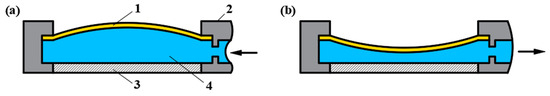
Figure 1.
Schematic diagram of hydraulic liquid lens. 1—elastic film; 2—container; 3—glass substrate; 4—fluid medium. (a) Positive focal power form; (b) Negative focal power form. The arrow represents the direction of the pressurized liquid.
2.2. The Principle of Double-Sided Telecentric Zoom Optical System
Figure 2 illustrates the ideal configuration of a double-sided telecentric optical system, wherein object point A is situated at the object-space focal point of Lens 1, and its conjugate image point A’ resides at the image-space focal point of Lens 2. The distinctive characteristic of the double telecentric lens lies in the precise placement of its aperture stop, which coincides with the image focus point of Lens 1 and the object focus point of Lens 2. This configuration guarantees that the chief rays remain parallel to the optical axis in both the object and the image space. Therefore, the double-sided telecentric lens maintains a constant magnification irrespective of any displacement of the object or image. This design effectively minimizes perspective errors, thereby ensuring consistent accuracy in object measurements. The unique properties of double telecentric lenses render them extensively applicable in precision measurement, defect detection, and a variety of other high-precision scenarios. In the double-sided optical system, the magnification of optical system (β) is given by
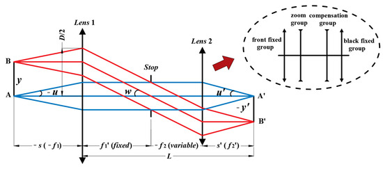
Figure 2.
The ideal model of double-sided telecentric lens. The Lens 1 and Lens 2 represent the front group and the rear group optical systems, respectively. The illustration (as indicated by the arrow) represents the structure of the rear group optical system.
In the equation, f1′ and f2′ denote the focal lengths of Lens 1 and Lens 2, respectively. Different magnifications can be achieved by adjusting the focal lengths of the lenses.
In the field of optical design, selecting an appropriate initial structure is pivotal to achieving optimal design outcomes. Nevertheless, to date, there is a lack of readily available initial structures for double-sided telecentric zoom optical systems utilizing liquid lens zoom technology. To identify an optimal initial configuration, this study initially designs a conventional double-sided telecentric zoom optical system; subsequently, the moving groups are replaced with liquid lenses to establish the baseline structure. Assuming Lens 1 is a lens with a fixed focal length, whereas Lens 2 is a zoom lens comprising a front fixed group, a zoom group, a compensation group, and a rear fixed group. The focal length of Lens 2 can be adjusted by manipulating the positions of the zoom and compensation groups, allowing for continuous variation in the magnification of the optical system. The design specifications for Lens 1 and Lens 2 are determined individually, and the appropriate initial structures are selected for optimization based on these design specifications. Subsequently, a conventional double-sided telecentric zoom optical system is designed by combining Lens 1 and Lens 2. Ultimately, liquid lenses are substituted for zoom and compensation groups based on the excellent performance of the conventional double-sided telecentric zoom optical system, and iterative optimization is conducted until the optical system meets the specified performance criteria. To enhance system compactness, a single liquid lens is utilized for both the zoom and compensation groups.
3. Design Results of Double-Sided Telecentric Zoom Optical System Based on Liquid Lens
3.1. Calculation and Analysis of Design Specifications
Telecentric lens possesses the characteristics of a large depth of field and high F-number (the reciprocal of relative aperture), which is conducive to enhancing the precision of dynamic measurement. In this design, the F-number is set to 8, and the dimensions of the detected workpieces range from 25 to 60 mm. Additionally, a Sony 2/3-inch CCD sensor is employed, featuring an effective area of 8.8 × 6.6 mm, a pixel size of 6.45 × 6.45 μm, and a diagonal size of 11 mm.
Based on the principles of geometric optics and the geometric relationships illustrated in Figure 2, the following equation can be derived.
Where, the parameters y and y’ denote the semi-object field of view and the semi-image field of view, respectively. The f1′ and f2′ are the rear focal lengths of Lenses 1 and 2, respectively. The w represents the angle between the chief ray passing through the first group and the optical axis, which is also the field of view angle of Lens 2. While u and u’ denote the aperture angle of object plane and image plane, and s and s’ denote the distances of the object and image, respectively.
According to the dimensions of the detected workpiece and the CCD sensor, we determine that 2y ranges from 25 mm to 60 mm, while 2y’ is 11 mm. The β falls within the range of −0.44× to −0.183× by substituting these values for 2y and 2y’ into Equation (2).
As can be seen from Figure 2, the aperture and F-number of Lens 1 (referred to as D and F1) are expressed as follows:
Then, the F-number of Lens 2 (F2) corresponds to the F-number of optical system (F):
The total length (L) of the system is as follows:
By Substituting Equation (2) into (6), and the following equation is obtained:
The above equations indicate that the focal length and F-number of Lens 1, the focal length of Lens 2, and the total length of the system are dependent on parameter w, while the parameters y, β, and F are held constant. As the value of w increases, the total length of the system decreases. However, this also results in a decrease in F-number for Lens 1, which, in turn, leads to a nonlinear increase in high-order aberrations. To effectively correct these aberrations and ensure high-quality imaging, it is imperative to design intricate structures for both Lens 1 and Lens 2. On the other hand, an excessively small value of w will result in an increase in the total length of the system, hindering the progress towards miniaturization. Therefore, the selection of an appropriate value for w is of paramount importance. When the focal length of Lens 1 is constant, Equations (2) to (4) indicate that the w of Lens 1 increases and the F-number of Lens 1 decreases as the magnification β decreases. To achieve optimal imaging quality across different magnifications, the w and F-number at low magnification serve as the design specifications for Lens 1. Following thorough analysis, the value of w at low magnification (−0.183×) is defined as 0.213 (approximately 12°). Consequently, the focal lengths of Lens 1 and Lens 2 are derived as f1′ = 141 mm and f2′ = 26 mm, respectively, with the working distance determined to be s = −141 mm. Based on Equation (3), the F-number of Lens 1 is determined to be F1 = 2.2, while Equation (5) indicates that the F-number of Lens 2 is F2 = 8. It is possible to determine the object field of view (2y) and the focal length of each lens for various magnifications according to Equations (2), and the specific values are presented in Table 1.

Table 1.
Object field of view and focal length at different magnification.
In summary, the design specifications for the double-sided telecentric zoom optical system, Lens 1, and Lens 2 are presented in Table 2.
Table 2.
Design specifications for a double-sided telecentric zoom optical system.
3.2. Initial Structure of Optical System
According to the design specifications outlined in Table 2, a five-element lens is adopted as the initial structure for Lens 1 [28], whereas the initial structure for lens 2 is selected from the ZEBASE lens library, as depicted in Figure 3. After determining the initial structures, the corresponding design specifications for Lens 1 and Lens 2 are established. Each lens is individually optimized, followed by their integration for further optimization.
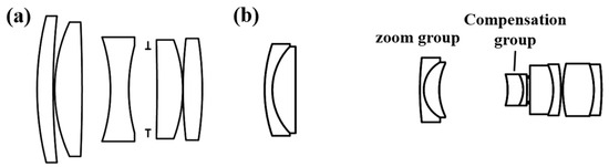
Figure 3.
Initial structure of optical system. (a) The initial structure of the front group (Lens 1) optical system; (b) The initial structure of the rear group (Lens 2) optical system.
Based on the superior imaging quality, liquid lenses are utilized to replace both the zoom group and compensation group. According to zoom range and aperture size requirement for the zoom group and the compensation group, the liquid lens (EL-16-40-VIS) from Optotune is selected for this design. The specific parameters are shown in Table 3.
Table 3.
The parameters of the liquid lens.
The liquid lens can form either a plano-convex or a plano-concave configuration. According to the geometric optics principles, the focal length can be calculated using the following formula:
Here, n represents the refractive index of fluid medium, while r1 denotes the radius of curvature of the lens surface. The radius of curvature of the liquid lens after replacement can be calculated using Equations (8) based on the known focal length. Ultimately, the initial structure of the double-sided telecentric zoom optical system based on the liquid lens is realized. As shown in Figure 4, this initial structure comprises two liquid lenses.
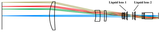
Figure 4.
Initial structure of double-sided telecentric zoom optical system based on the liquid lens. Light of different colors represents different fields of view.
3.3. Optimization
Following the determination of the initial optical configuration, optimization is required to improve its imaging quality. During the optimization process, it is imperative to rigorously control boundary conditions, including the center thickness, edge thickness, and material properties of the lens, to ensure both the performance of the optical system and the feasibility of manufacturing. Utilizing the multi-configuration feature of Zemax software, the radius of curvature of the liquid lens is configured as a variable, enabling continuous zooming through dynamic adjustment of this parameter. We apply the REAY operand to precisely regulate the height of each layer, ensuring that the magnification of each structure conforms to the design specifications. The magnification can be controlled using the REAY operand. Telecentricity serves as a crucial metric for assessing the performance of the double-sided telecentric optical system and must be meticulously controlled. Object-space telecentricity can be effectively regulated using the software’s telecentricity function. For image-space telecentricity, this can be achieved using the RANG operand. Specifically, the target value of zero-aperture for each field on the image plane is set to zero, ensuring that the chief ray remains parallel to the optical axis. The double-sided telecentric optical system has a strict demand on its distortion. Therefore, controlling system distortion is essential. In this design, DIMX operand is utilized to control distortion, ensuring compliance with the system’s design specifications. In addition, t exhibits significant aberrations. To correct lateral aberration of the optical system, the aperture is positioned midway between the two liquid lenses, resulting in an approximated symmetrical structure. Meanwhile, the doublet lens positioned in front of the first liquid lens is decomposed into two separate lenses, enhancing the system’s design flexibility and enabling more efficient optimization of aberration correction and imaging quality. In optical system design, lenses positioned near the aperture stop are primarily responsible for the correction of spherical and coma aberrations. Given the limited capability of liquid lenses in correcting aberrations, a thick lens is introduced between the liquid lenses to compensate for aberrations. Furthermore, the spherical and coma aberrations can also be optimized through merit function operands such as LONA and TRAY to achieve optimal optical performance. Additionally, given the relatively large aperture of the first lens, H-K9L glass, which provides a superior cost-performance, is selected to reduce costs. Simultaneously, the materials of other lenses are optimized using the hammer optimization function to further minimize aberrations. To achieve a more compact design, we utilize the TOTR evaluation function to regulate the overall system length. Through iterative refinement of lens parameters via the prescribed methodology, the system’s imaging performance is progressively enhanced to achieve diffraction-limited quality.
4. Analyses and Discussion
4.1. Analysis of Optimization Results
The final optimized optical system structure is illustrated in Figure 5, comprising nine spherical lenses and two liquid lenses, with an overall length of 275 mm. As illustrated in Figure 5a–d, the positions of all system components remain unchanged across different magnification levels, with only the radius of the curvature of the liquid lens undergoing variation. Figure 6a illustrates the optical power of the liquid lenses at various magnifications, which correspond to the specified optical focal length range of the selected liquid lenses. To effectively improve the magnitude of the optical power variation at the liquid lenses, the optical powers of the liquid lenses are set to be symmetric with opposite signs at the maximum and minimum magnifications. In addition, the focal power of the liquid lens exhibits a smooth curve profile with varying magnification, demonstrating that continuous zoom functionality of the system can be achieved through controlled modulation of the liquid lens’s focal power. Figure 6b illustrates the lateral color aberrations of the double-sided telecentric zoom system at various magnifications, which are less than 0.05 mm within the fully normalized pupil; thus, aberrations are significantly reduced.
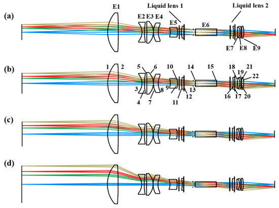
Figure 5.
The final optical system structure: (a) the structure at a magnification of −0.44×; (b) the structure at a magnification of −0.33×; (c) the structure at a magnification of −0.275×; (d) the structure at a magnification of −0.183×. Light of different colors represents different fields of view.
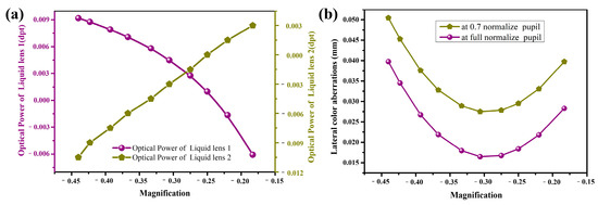
Figure 6.
System characteristics at various magnifications: (a) the optical power of the liquid lens at various magnifications; (b) lateral color aberrations of the double-sided telecentric zoom system at various magnifications.
The performance of the optimized double-sided telecentric zoom optical system can be evaluated using a variety of metrics, including spot diagrams, modulation transfer function (MTF), distortion, and telecentricity. Figure 7 illustrates the spot diagram of this zoom system. The dispersion spots across all fields of view at different magnifications are confined within airy disks, with the root-mean-square (RMS) radius consistently smaller than the pixel size of CCD sensor. This indicates that the aberrations have been effectively corrected.
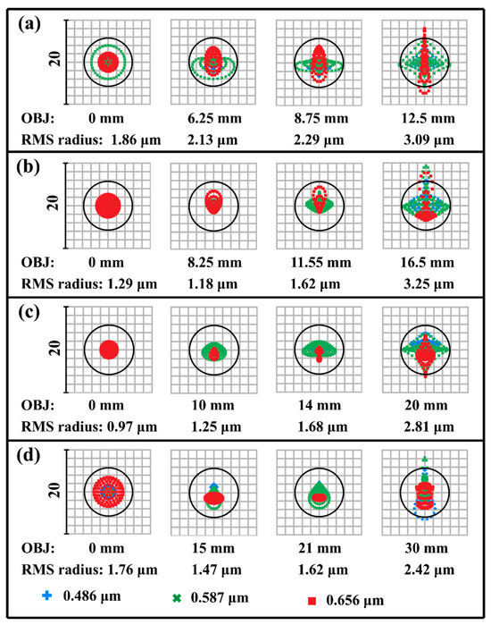
Figure 7.
Spot diagram: (a) spot diagram at a magnification of −0.44; (b) spot diagram at a magnification of −0.33×; (c) spot diagram at a magnification of −0.275×; (d) spot diagram at a magnification of −0.183×.
In this design, the pixel size of the image sensor is σ = 6.45 µm. Based on this, the Nyquist frequency is calculated as N = 1/(2σ) = 78 lp/mm. Therefore, the modulation transfer function (MTF) value at a spatial frequency of 80 lp/mm is adopted as the evaluation criterion. As illustrated in Figure 8, the MTF values at various magnifications exceed 0.4 at the Nyquist frequency of 80 lp/mm and approach the diffraction limit. This demonstrates that the double-sided zoom optical system exhibits superior imaging performance.
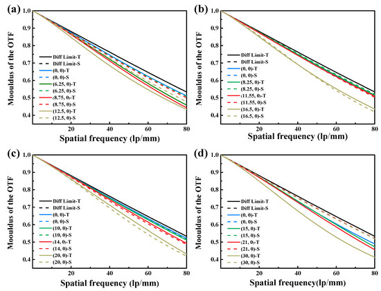
Figure 8.
MTF curves: (a) MTF curve at a magnification of −0.44×; (b) MTF curve at a magnification of −0.33×; (c) MTF curve at a magnification of −0.275×; (d) MTF curve at a magnification of −0.183×.
Distortion serves as a crucial metric for characterizing object deformation. While distortion does not impact system clarity, it must remain within acceptable range in industrial inspection to guarantee accuracy. The distortions of the double-sided telecentric zoom optical system at various fields of view across different magnifications are illustrated in Figure 9. The maximum distortion is merely 0.05% at a magnification of −0.33×, while the maximum distortion is maintained within 0.2% at other magnifications, fulfilling the system’s design specifications. The system exhibits minimal distortion during the magnification process, which facilitates improved measurement accuracy.
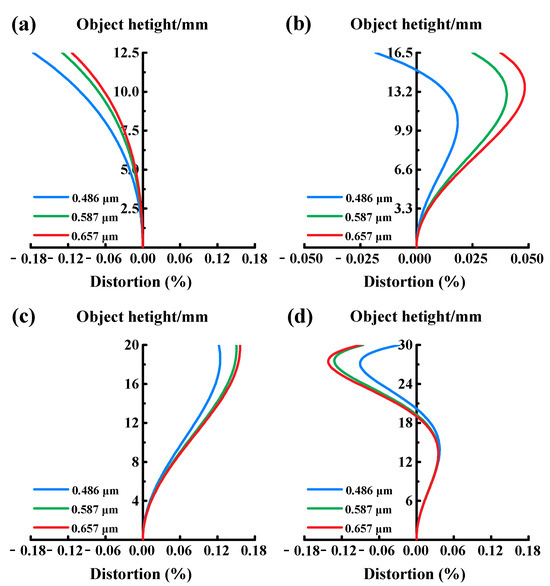
Figure 9.
The distortion of double-sided telecentric zoom optical system: (a) the distortion at magnification of −0.44×; (b) the distortion at magnification of −0.33×; (c) the distortion at magnification of −0.275×; (d) the distortion at magnification of −0.183×.
Telecentricity is a critical parameter for assessing the performance of a double telecentric lens. It represents the angle between the chief ray and the optical axis, where an angle of zero signifies absolute telecentricity. Figure 10 depicts the distribution of incident angles at the image plane, wherein these angles serve as an indicator of the telecentricity. As illustrated in the figure, at magnifications of −0.44×, −0.333×, −0.275×, and −0.183×, the corresponding maximum incident angles within the full field of view are 0.45°, 0.12°, 0.36°, and −0.46°, respectively. These results indicate that the system’s telecentricity remains below 1°, satisfying the design specification.
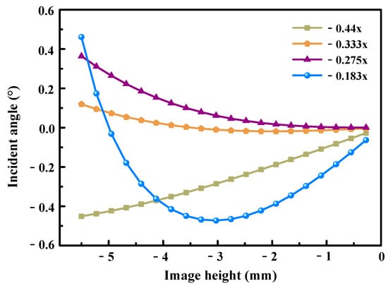
Figure 10.
The distribution of incident angles at the image plane.
4.2. Tolerance Analysis
During the manufacturing and assembly processes, inevitable errors may cause deviations between the actual imaging quality of products and the expected design outcomes [29,30]. Therefore, upon completion of theoretical design, it is critical to evaluate the feasibility of the design against established manufacturing constraints. Furthermore, to enhance the precision of optical surface processing and optimize system assembly performance, conducting a scientific tolerance analysis for the optical system is imperative. This process not only enhances production efficiency but also effectively reduces manufacturing costs.
In tolerance analysis, the primary sources of error that require analysis include machining error, assembly error, and material error. Machining errors encompass the radius of curvature, surface irregularity, central thickness, decentration and tilt of the lens surface. Assembly errors include element decentration, element tilt, and the air gap between lenses. Material errors are characterized by variations in the refractive index and Abbe number of the material. These errors are simulated using Zemax software (2023 R1), and their impact on system performance is analyzed to determine appropriate tolerances, ensuring optimal optical system performance post-machining.
The tolerance analysis procedure follows a cost-driven optimization principle: initial tolerance values are deliberately assigned with generous margins to minimize manufacturing costs, followed by precision refinement of critical components identified through statistical simulation. This “lenient baseline with localized tightening” strategy ensures optimal balance between production economy and imaging performance. The specific steps are as follows: First, an initial set of tolerance values is established based on current manufacturing technology standards and system performance requirements. Second, the sensitivity of each tolerance parameter to performance degradation is calculated and analyzed, and the tolerance values for sensitive optical components are subsequently tightened to mitigate critical deviations. Ultimately, the above steps are iteratively repeated, with tolerance values continuously refined until optimal tolerance allocation is achieved, enabling robust performance prediction. According to the [30], this design adopts an industrial-grade tolerance range (Q5–Q8 levels), which is applicable to general inspection systems. Therefore, the initial tolerance settings for this design are as follows: 5 fringes for the radius of curvature, 0.5 fringes for surface irregularity, 0.05 mm errors for both center thickness and air gap, 0.01 mm errors for both surface decentration and element decentration, and 2′ errors for both surface tilt and element tilt, with errors of 0.001 for the refractive index and 0.8% for the Abbe number. The back focal length is utilized as a compensator to correct deviations that arise during the machining and assembly of the optical system, and sensitivity analysis methods and Monte Carlo simulations are employed to evaluate the sensitivity of performance degradation associated with these initial tolerance parameters. Given the unique tolerance characteristics of liquid lenses, our analysis focuses on two critical parameters: First, liquid evaporation rate was modeled as thickness variation in the liquid layer. For sealing failure metrics, decentration and tilt errors (simulated via TSDX/TSTY operands) were introduced to characterize membrane deformation under pressure cycling conditions.
For a double-sided telecentric optical system, stringent requirements are imposed on imaging quality, with particular emphasis on minimizing distortion and maintaining high telecentricity. Therefore, in evaluating system performance, the primary considerations are the MTF value at 80 lp/mm, system distortion, and telecentricity. These parameters are used to assess the sensitivity of performance degradation to variations in system parameters. Following the calculation and analysis of initial tolerance values, the modulation transfer function (MTF) of different magnifications satisfied system requirements. However, at low magnification, both distortion and full-field telecentricity are inadequate, failing to satisfy the system’s requirements. Figure 11a illustrates the ten most sensitive tolerance values that significantly affect distortion and telecentricity at a magnification of −0.183×. As indicated in Figure 11a, distortion is predominantly influenced by the machining and assembly errors associated with element 2 (E2) and element 3 (E3). These errors encompass surface tilt, component decentration, and surface decentration for both E2 and E3. Additionally, the air spacing between the lenses, the central thickness of E2, and its material refractive index were also significant sources of error. The refractive index of element 1 (E1) exerts the most significant influence on telecentricity. Consequently, it is crucial to rigorously control these machining and assembly errors associated with E1 and to further tighten the tolerance values to ensure optimal system performance.
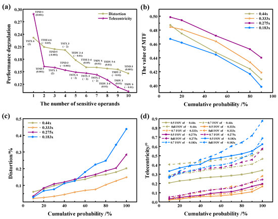
Figure 11.
Tolerance analysis results: (a) the most sensitive operand; (b) the cumulative probability of MTF; (c) the cumulative probability of distortion; (d) the cumulative probability of telecentricity.
The optimized tolerance allocation is displayed in Table 4 following thorough adjustments and careful calculations. Based on the tolerance allocation values detailed in Table 4, 50 Monte Carlo simulations are performed. The resulting probability distributions of the modulation transfer function (MTF), distortion, and telecentricity are illustrated in Figure 11b–d. As illustrated in Figure 11b, the MTF values for 90% of the samples at magnifications of −0.44×, −0.333×, −0.275×, and −0.183× are 0.409, 0.418, 0.440, and 0.398, respectively. Figure 11c,d demonstrate that the distortion magnitude remains below 0.5 for all samples during the zooming process, and telecentricity within each field of view being less than 1°.
Table 4.
The final tolerance allocation.
The analysis demonstrates that the design maintains high performance post-manufacturing and fully complies with the specified design requirements. Moreover, the finalized tolerance allocations reflect moderate processing complexity, thereby validating the design’s high manufacturability and implementation feasibility.
4.3. Discussion
Conventional zoom double-sided telecentric systems exhibit structural complexity and excessive bulkiness. This stems primarily from their standard three-group configuration, comprising fixed, movable, and compensation groups, where focal length variation relies on mechanical motion of movable elements, while image plane stabilization necessitates compensatory motion of the compensation group. However, redundant mechanical structures exacerbate system intricacy and impede dimensional control. Coupled with stringent telecentricity requirements, these factors pose significant challenges for miniaturization and lightweight design imperatives in contemporary applications. The emergence of novel zoom elements such as liquid lenses overcomes the limitations of conventional zoom systems, enabling the development of displacement-free zoom configurations. In such systems, both focal length variation and image plane stabilization are achieved entirely via dynamic focal length modulation of the zoom elements. Design analysis verifies that the double-sided telecentric zoom optical system with liquid lenses demonstrates exceptional imaging quality, minimal distortion, outstanding telecentricity, and favorable tolerance performance. Crucially, the liquid lens employed in this design is commercially available, with its optical power electrically adjustable via control voltage. Consequently, constructing the physical prototype of the zoom system is relatively straightforward, while the “electrically controlled zoom” capability inherent to liquid lenses enables full-system automation. In conclusion, compared to traditional double-sided telecentric zoom systems, the utilization of liquid lenses for zooming effectively mitigates challenges such as focus inaccuracies induced by mechanical movements and structural complexity, rendering this optical system highly promising for industrial inspection and defect detection applications.
However, in industrial-grade applications, the long-term stability and reliability of liquid lenses still face severe challenges, primarily constrained by bottlenecks such as dielectric failure, material aging, and environmental resilience. Common problems encountered during the use of liquid lenses include the following: drift in voltage focal length curves due to dielectric layer degradation or liquid evaporation after prolonged use; optical axis misalignment and increased wavefront error caused by liquid interface displacement under industrial vibration; significant response time degradation due to viscosity shifts during thermal fluctuations, failing real-time focusing requirements; and complete functional failure from dielectric breakdown when microcracks propagate in insulation layers under high voltage. Therefore, before achieving industrial application, the stability and reliability of the liquid zoom optical system must be experimentally validated. We propose a 12-month accelerated aging test under simulated operational conditions (temperature: −10 °C to 60 °C; humidity: 30–85% RH) to evaluate performance degradation of the integrated system. Parameters include focal-length drift, MTF (modulation transfer function) decay, hysteresis error, and repeatability (repeatability is evaluated by 100 zoom cycles), measured at 0/3/6/12-month intervals. Additionally, field tests will deploy prototypes in industrial inspection settings (e.g., automatic optical inspection lines) to monitor reliability under sustained workloads (8 h per day). Mechanical robustness (e.g., lens displacement under 5–500 Hz vibration) and thermal resilience (20 cycles from −20 °C to 70 °C) can also be quantified. Furthermore, long-term failure rates (e.g., dielectric breakdown, fluid leakage) will be recorded, and the average time interval between failures will be calculated. In conclusion, for industrial applications, suitable liquid lenses should be carefully selected according to the specific usage environment. On the other hand, a performance margin of at least 20% should be reserved in the design phase to account for potential system instability. Moving forward, addressing these limitations via cross-disciplinary innovations will enable liquid zoom lenses to evolve from laboratory prototypes into robust industrial solutions.
5. Conclusions
In this paper, we propose a design method for a double-sided telecentric zoom optical system incorporating liquid lenses. A conventional double-sided telecentric zoom system is developed through mechanistic analysis of telecentricity maintenance principles and liquid lens focal modulation characteristics, followed by parametric calculation. Subsequently, the liquid lens substitutes conventional magnification/compensation groups for refined optical optimization. This system comprised a total of nine spherical lenses and two liquid lenses. And it enables the continuous detection of objects with sizes ranging from 25 to 60 mm and a magnification range of −0.44× to −0.183×. This optical system exhibits exceptional imaging performance, minimal distortion, and superior telecentricity. The diffuse spot is primarily controlled within the airy spot. And the MTF closely approximates the diffraction limit at a Nyquist frequency of 80 lp/mm. The distortion and telecentricity are both below 0.2% and 0.5°, respectively. Compared with the conventional zoom system, the proposed system has a simplified structure and effectively overcomes the inaccurate focus resulting from optical element movement. Moreover, the manufacturing and assembly tolerances is this system exhibit exceptional precision in machining, and assembly tolerances are simple to implement, having a superior level of processing. This system has a wide range of application prospects in machine vision industrial inspection.
Author Contributions
Conceptualization, X.C. and Y.H.; methodology, Y.H. and H.Z.; software, X.C. and Y.H.; writing—original draft preparation, X.C.; writing—review and editing, Y.H. and H.Z.; visualization, X.C.; supervision, H.Z.; funding acquisition, X.C., Y.H., and H.Z. All authors have read and agreed to the published version of the manuscript.
Funding
This research was funded by the Natural Science Foundation of Fujian Province of China (Nos: 2025H6101, 2024J01950); the Key Scientific and Technological Innovation Projects of Fujian (No: 2022G02026).
Institutional Review Board Statement
Not applicable.
Informed Consent Statement
Not applicable.
Data Availability Statement
Data are contained within the article.
Conflicts of Interest
The authors declare no conflicts of interest.
References
- Zhang, Y.; Ma, X.; Zhang, F.; Huang, H. Telecentricity measurement for exposure system of photolithography tools. Opt. Eng. 2020, 59, 034109. [Google Scholar] [CrossRef]
- Jiang, H.; Sun, X.; Yang, R.; Chen, J.; Xie, L.; Yin, S. Design of UV LED illumination system for direct imaging lithography. Opt. Eng. 2019, 58, 075103. [Google Scholar]
- Wang, X.; Zhu, D.; Shi, W.; Liu, J.; Fu, F.; Li, J.; Zhang, X. Multi-depth-of-field 3-D profilometry for a microscopic system with telecentric lens. IEEE Trans. Instrum. Meas. 2021, 71, 1–9. [Google Scholar] [CrossRef]
- Zhang, K.; Li, J.; Sun, S.; Wang, J.; Yu, S. Optical system design of double-sided telecentric microscope with high numerical aperture and long working distance. Opt. Express 2023, 31, 23518–23532. [Google Scholar] [CrossRef] [PubMed]
- Liu, L.H.; Feng, Y.; Nong, L.H.; Tang, X.H. Three-magnification double-telecentric optical system and effect of field on optical design. Laser Optoelectron. Prog. 2022, 59, 300–308. [Google Scholar]
- Zhang, J.; Wang, X.; Chen, X.; Li, F.; Liu, H.; Cui, H.; Sun, X. Paraxial lens design of double-telecentric anamorphic zoom lenses with variable magnifications or fixed conjugate. J. Opt. Soc. Am. A 2019, 36, 1977–1990. [Google Scholar] [CrossRef] [PubMed]
- Mikš, A.; Novák, J. Design of a double-sided telecentric zoom lens. Appl. Opt. 2012, 51, 5928–5935. [Google Scholar] [CrossRef]
- Zhang, J.; Chen, X.; Xi, J.; Wu, Z. Paraxial analysis of double-sided telecentric zoom lenses with four components. Opt. Eng. 2014, 53, 115103. [Google Scholar] [CrossRef]
- Zhang, J.; Chen, X.; Xi, J.; Wu, Z. Aberration correction of double-sided telecentric zoom lenses using lens modules. Appl. Opt. 2014, 53, 6123–6132. [Google Scholar] [CrossRef]
- Ye, W.W.; Huang, J.Y.; Zhou, T.F.; Lin, F. Design of continuous zoom double telecentric system and analysis of cam curve. Laser Optoelectron. Prog. 2020, 57, 218–224. [Google Scholar]
- Fan, Z.; Wei, S.; Zhu, Z.; Mo, Y.; Yan, Y.; Ma, D. Automatically retrieving an initial design of a double-sided telecentric zoom lens based on a particle swarm optimization. Appl. Opt. 2019, 58, 7379–7386. [Google Scholar] [CrossRef] [PubMed]
- Huang, Y.; Chen, X.; Zhang, H.; Li, X. Optical design of a double-sided telecentric zoom system with large field of view. Opt. Commun. 2025, 583, 131765. [Google Scholar] [CrossRef]
- Kuiper, S.; Hendriks, B.H. Variable-focus liquid lens for miniature cameras. Appl. Phys. Lett. 2004, 85, 1128–1130. [Google Scholar] [CrossRef]
- Mikš, A.; Novák, J. Analysis of two-element zoom systems based on variable power lenses. Opt. Express 2010, 18, 6797–6810. [Google Scholar] [CrossRef]
- Mikš, A.; Novák, J. Third-order aberrations of the thin refractive tunable-focus lens. Opt. Lett. 2010, 35, 1031–1033. [Google Scholar] [CrossRef]
- Mikš, A.; Novák, J. Paraxial imaging properties of double conjugate zoom lens system composed of three tunable-focus lenses. Opt. Lasers Eng. 2014, 53, 86–89. [Google Scholar] [CrossRef]
- Hao, Q.; Cheng, X.; Du, K. Four-group stabilized zoom lens design of two focal-length-variable elements. Opt. Express 2013, 21, 7758–7767. [Google Scholar] [CrossRef] [PubMed]
- Jo, S.H.; Park, S.C. Design and analysis of an 8x four-group zoom system using focus tunable lenses. Opt. Express 2018, 26, 13370–13382. [Google Scholar] [CrossRef]
- Liu, Z.; Gan, Z.; Zhang, M.; Lv, J.; Xing, K.; Hong, H. Design of a small non-displacement zoom optical system based on Gaussian brackets and traversal ideation. Opt. Commun. 2024, 557, 130336. [Google Scholar] [CrossRef]
- Mikš, A.; Novák, J. Double-sided telecentric zoom lens consisting of four tunable lenses with fixed distance between object and image plane. Appl. Opt. 2017, 56, 7020–7023. [Google Scholar] [CrossRef]
- Li, J.; Zhang, K.; Du, J.; Li, F.; Yang, F.; Yan, W. Design and theoretical analysis of the image-side telecentric zoom system using focus tunable lenses based on Gaussian brackets and lens modules. Opt. Lasers Eng. 2023, 164, 107494. [Google Scholar] [CrossRef]
- Li, J.; Zhang, K.; Du, J.; Li, F.; Yang, F.; Yan, W. Double-sided telecentric zoom optical system using adaptive liquid lenses. Opt. Express 2023, 31, 2508–2522. [Google Scholar] [CrossRef] [PubMed]
- Edmundoptics. Available online: https://www.edmundoptics.com/f/mercurytl-liquid-lens-telecentric-lenses/37273/ (accessed on 7 June 2025).
- Opto Engineering. Available online: https://www.opto-e.com/en/products/telecentric-lenses (accessed on 7 June 2025).
- Optotune. Available online: https://www.optotune.com/elm-t-series (accessed on 7 June 2025).
- Cheng, Y.; Cao, J.; Tang, X.; Hao, Q. Optical zoom imaging systems using adaptive liquid lenses. Bioinspir. Biomim. 2021, 16, 041002. [Google Scholar] [CrossRef] [PubMed]
- Ren, H.; Fox, D.; Andrew Anderson, P.; Wu, B.; Wu, S.T. Tunable-focus liquid lens controlled using a servo motor. Opt. Express 2006, 14, 8031–8036. [Google Scholar] [CrossRef]
- Fujian Research Institute on Optical Technology, State Red Electromechanical Factory. Hand-Book of Optical Lens; National Defense Industry Press: Beijing, China, 1980; Volume 1, p. 60. [Google Scholar]
- Li, Q.Y.; Zhang, Y.; Yan, S.Y.; Zhang, B.; Wang, C.H. Design of three-dimensional imaging lidar optical system for large field of view scanning. Chin. Phys. B 2022, 31, 074201. [Google Scholar] [CrossRef]
- Chang, C.W.; Ho, G.H.; Wang, C.L.; Chao, W.C.; Griffith, J.D. Tolerance analysis of lenses with high zoom ratio. In Proceedings of the SPIE, Changchun, China, 1 February 2006. [Google Scholar]
Disclaimer/Publisher’s Note: The statements, opinions and data contained in all publications are solely those of the individual author(s) and contributor(s) and not of MDPI and/or the editor(s). MDPI and/or the editor(s) disclaim responsibility for any injury to people or property resulting from any ideas, methods, instructions or products referred to in the content. |
© 2025 by the authors. Licensee MDPI, Basel, Switzerland. This article is an open access article distributed under the terms and conditions of the Creative Commons Attribution (CC BY) license (https://creativecommons.org/licenses/by/4.0/).