Abstract
The low-chirp operation of distributed feedback lasers is highly desirable in high-speed and high-bit rate optical transmission. In this article, we address this issue by theoretically investigating the possibility of further a reduction in the linewidth enhancement factor (LEF) of a quantum well (QW). The energy band structure of AlGaInAs quantum-well DFB lasers grown with a (110) crystal orientation in the active region of the L-band has been theoretically analyzed using multi-band k.p perturbation theory, by reducing the asymmetry of conduction bands and valence bands and thus the linewidth enhancement factor parameter, which is related to the frequency chirp. Simulation results show that the LEF of the directly modulated DFB laser is reduced from 2.434 to 1.408 by designing the (110)-oriented compression-strained Al0.06Ga0.24InAs multiple-quantum-well structure, and the eye diagram of the (110)-oriented quantum-well DFB laser with a digital signal transmission of 20 km is significantly better than the (001) crystal-oriented quantum-well DFB laser for the 10Gbps optical fiber communication system, thus achieving a longer distance and higher-quality optical signal transmission.
1. Introduction
With the expansion of the Ethernet, data centers, metro access networks, and enterprise networks, increasing network traffic is spurring the need for high-speed, low-cost, low-power, and long-haul optical transmission equipment [1,2]. High-speed optical transmitters reported to date include directly modulated distributed feedback (DFB) lasers [3,4] and DFB lasers with integrated electro-absorption modulators (EAMs) [5,6,7]. Among them, the current-based direct modulation scheme is widely used as an optical transmitter for access networks and data center networks due to its advantages of having a small size, a low cost, and low power consumption, which is ideal for short- and medium-range optical communication systems. Directly modulated lasers (DMLs) now have higher bandwidths and are capable of supporting higher bit rates, including 10, 25, and even 50 Gb/s [8,9]. Passive optical network (PON) technology serves as the broadband access solution, with 10 Gigabit PON systems primarily utilizing the L-band for downlink transmission from the optical line terminal (OLT). Moreover, to maintain backward compatibility with existing wavelength allocations, the new standard defines 1577 nm as the downstream transmission center wavelength. However, when using L-band DMLs in standard single-mode fiber (SSMF) transmission, the dispersion caused by chirp severely limits the transmission distance [10,11,12]. The positive chirp that is inherent in directly modulated lasers (DMLs) induces pulse broadening, limiting their practical utility in fiber-optic communication systems. However, various complex techniques exist for chirp reduction and control under direct modulation. Notably, the pre-chirp technique implemented through digital signal processing (DSP) can extend the transmission distance beyond 200 km [13]. The chirp management laser (CML) presents another solution [14]. However, DSP-based approaches increase system complexity, while CMLs still require reductions in both cost and size. Consequently, compact, low-chirp, and cost-effective 10 Gb/s DMLs remain essential for long-haul transmission in metro access and data center network applications.
In general, for DMLs, current modulation within the active region simultaneously induces variations in both photon density and carrier density. Gain modulation through carrier density variation subsequently alters the refractive index in the active region. The current-dependent modulation of the cavity field distribution consequently generates a lasing frequency shift , which correlates with the carrier density variation as [15]:
where is the LEF, is the frequency chirp, is the differential gain, is the carrier density variation, is the group velocity in the active section. Equation (1) clearly demonstrates that the frequency chirp is primarily determined by and , indicating that reducing these parameters is essential for minimizing the chirp effect. The reduction of typically results in the degradation of the extinction ratio. The linewidth enhancement factor plays a key role in optical transmission which is typically reduced through gain detuning design [16,17], p-type carrier injection [18], and compressive strain to alter the quasi-Fermi level of valence band holes, thereby lowering the linewidth broadening factor [19]. However, detuned DFB lasers generally exhibit higher thresholds and reduced optical gain, which degrades the power characteristics of semiconductor lasers. Excessive p-type carrier concentration can introduce additional recombination centers and increase non-radiative recombination, severely impacting laser performance [16]. Currently, there is no suitable method to effectively reduce frequency chirp under the direct modulation of DMLs. Ohtoshi et al. studied the energy band structure of (11N) grain-oriented InGaAs materials and proposed that the energy band structure is closely related to the growth direction of the quantum well, and that different valence band structures can be realized by rotating the orientation to change the optical gain of the quantum well [20]. To date, the orientation-dependent linewidth enhancement factor and eye diagram quality have not been investigated in detail for L-band-strained AlGaInAs QW directly modulated DFB lasers.
In this paper, we propose a substrate orientation as a new degree of freedom for chirp control in DMLs, examining LEF-dependent modulation properties of L-band AlGaInAs/InP QW DFB lasers across different substrate orientations. Based on the foundation of previous studies on photoelectric properties for 850 nm VCSELs with arbitrary crystal orientations, the density of states (DOS), differential gain, and LEF of the (001)- and (110)-oriented AlGaInAs quantum wells are scrutinized. We reveal that the gain and LEF parameters depend on the growth crystal orientation of the quantum wells. Eye diagram simulations are computed for a 10 Gb/s signal transmitted over 20 km using a directly modulated DFB laser in the (001) and (110) orientation, respectively, and a lower chirp is achieved with a DFB laser with the (110) substrate QW.
The article is structured as follows: the theoretical formulation and numerical techniques are presented in Section 2. Section 3 describes the DOS, optical gain, differential gain, and LEF of strain quantum wells grown in (001) and (110) crystal orientations. After optimizing the parameters of the active region, the eye diagrams are simulated to obtain the transmission of 10 Gbps (NRZ) optical signals over 20 km with a center wavelength of 1577 nm with direct modulation. This work is finally summarized in Section 4.
2. Theoretical
The linewidth enhancement factor (LEF) and differential gain are the two most crucial parameters in semiconductor laser design, each exerting a decisive influence on the optical frequency chirp in fiber-optic communication systems. The LEF is related to the differential gain by Kramers–Kronig transform. The LEF is defined as the ratio of the real part to the imaginary part of the differential susceptibility with respect to carrier density N [10]:
where is central wavelength, is the refractive index change, is the material gain, and is the carrier concentration. The real part of refractive index change is . The factor of the interband transitions can be obtained by the following equation [21]:
where and represent the magnitude and angle of the in-plane wave vector within the quantum well, respectively. is permittivity, is the width of the QW, and is the refractive index. denotes the photon energy, is the valence band’s energy. and are Fermi–Dirac distribution functions. represents the momentum matrix of the valence and conduction sub-band, respectively. The intra-band relaxation time is assumed to be 0.1 ps when a Lorentzian broadening function is applied to quantum well lasers [22,23]. The optical gain of the QW can be expressed by the following equation:
The change in the real part of the permittivity (3) can be derived using (4) in the Kramers–Kronig relation in the limit of zero linewidth to obtain an analytical expression. Hamiltonians for different substrate orientations can be derived from the conventional crystal-oriented Hamiltonian [20]:
where (hkl) in the Hamiltonian refers to crystallographic orientations, , and indicate the spinor rotations [24]. is a four-band k·p method with strain effects. The valence bands of QW with various orientations can be calculated using the finite difference method (FDM):
From Equation (2), the refractive index change and differential gain for different crystal orientations can be derived, thereby obtaining the linewidth enhancement factor (LEF) parameter.
3. Numerical Simulation
The density of states and average valence sub-band energy of the (001)- and (110)-oriented compressively strained AlGaInAs quantum wells are calculated. The corresponding results are shown in Figure 1a–d, respectively, where HH{n} and LH{n} applies for the heavy holes and light holes (n = 1, 2,…). The density of states (DOS) plays a critical role in determining carrier occupation in quantum wells, and the quasi-Fermi energy levels in both conduction and valence bands are governed by the density of states at given carrier concentrations. In Figure 1, the position of sub-bands strongly depends on the growth direction and the DOSs of both crystal-oriented quantum wells are stepped. For the (001) crystal orientation, the density of states (DOS) exhibits gradual suppression with increasing energy, attributable to enhanced valence bands splitting. However, the density of states (DOS) already exceeds the band-edge value by a factor of four at approximately 50 meV below the band edge (see Table 1). On the other hand, the density of states in the (110) crystal-oriented quantum well is less than 2 × 10¹⁸ m−2eV−1in the energy range of 97 meV. It is noticed in Figure 1b that for the (110) orientation, the energy separation between the first hole band (HH1) and the next bands (HH2, LH1) is much larger than in the (001) case, which is the primary reason that the DOS for the (110) case remains low over a wider energy range. The reduced density of states (DOS) near the valence band edge decreases the available carrier density for population inversion, consequently lowering the laser threshold current. In addition, it is expected to increase the differential gain of the quantum well.
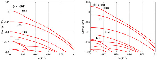
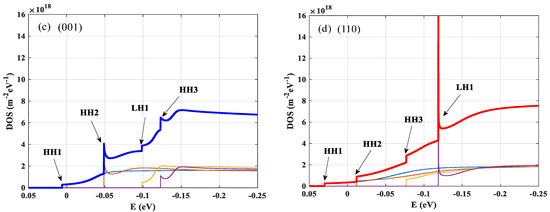
Figure 1.
The valence bands and density of states for (a,c) (001)- and (b,d) (110)-oriented compressive strained AlGaInAs QWs.

Table 1.
The DOS value of the (001) orientation.
To ensure its wavelength in the L-band, the quantum well width is set to 6 nm, the quantum well width was optimized to 6 nm to achieve L-band emission, while a 10 nm barrier width was selected to sufficiently suppress coupling between multiple quantum wells (MQWs), and the compressed strain (CS) caused by the lattice mismatch between the quantum well and the substrate is 1.15%. As shown in Figure 2, the gain spectra of the compression-strained Al0.06Ga0.24InAs quantum well grown in the (110) substrate direction are simulated at different carrier-injections. With the continuous increase in the injected carrier concentration, the peak gain increases, and when the carrier concentration reaches a critical value, the gain tends to saturation, owing to the fact that the electrons occupy the low energy levels of the conduction band, the newly injected carriers fill the higher energy levels of the electrons, and the quasi-Fermi energy levels of the conduction band increase slower with the increase in the concentration, which is also known as the energy band filling effect.
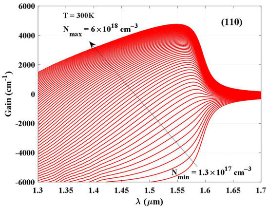
Figure 2.
The gain spectra of the compression-strained Al0.06Ga0.24InAs quantum well with the (110) orientation.
Figure 3 compares the linewidth enhancement factor and differential gain spectra between (110)- and (001)-oriented quantum wells at various threshold gain levels. The differential gain spectra of (110)-oriented quantum wells exhibit a distinct redshift relative to (001)-oriented QWs, accompanied by significant magnitude enhancement across all threshold gain conditions. The LEFs in the substrate (110) direction are 1.009 and 1.408 for gain thresholds of 500 cm−1 and 2000 cm−1, respectively, while the values are 1.908 and 2.434 for the conventional substrate direction. The reduction in the linewidth enhancement factor due to the DOS of the (110)-oriented quantum well decreases (as shown in Figure 1) enables the effect of chromatic dispersion on the optical signal to be reduced in fiber transmission, especially in the fiber transmission of L-band optical signals, to reduce the bit error rate.
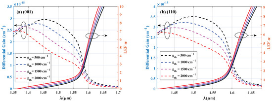
Figure 3.
The LEF and differential gain spectra for (a) (001)- and (b) (110)-oriented quantum wells are shown at various threshold gains.
As shown in Figure 4, we use the material gain and the corresponding carriers calculated for the (110) crystal orientation and the (001) crystal orientation to perform a logarithmic fit to obtain the transparent carrier concentration and the gain coefficients . The fitted gain–carrier density curves for both (001)- and (110)-oriented quantum wells demonstrate excellent agreement with logarithmic functional dependence [25]. It is found that the transparent carrier density in the (110) orientation decreases from 1.28 × 1018 cm−3 to 1.11 × 1018 cm−3 compared to the conventional (001) crystallographic direction, while the gain coefficient exhibits a significant enhancement from 2710.4 cm−1 to 3120.6 cm−1.
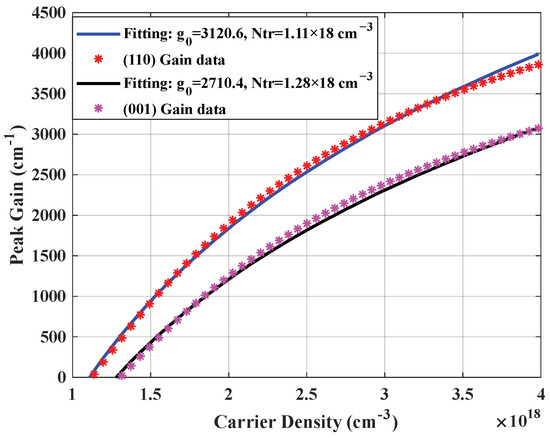
Figure 4.
Gain and carrier density curve fittings for the (001)- and (110)-oriented strained InAlGaAs quantum well.
Figure 5 shows the three-dimensional structure of the DFB laser with a dual-channel ridge waveguide structure, which from bottom to top includes the N side contact metal, the InP substrate and buffer layer, the bottom GRINSCH region, the active region, the top GRINSCH region, the grating layer, the cladding layer, the cap layer, and the P side contact metal. The quantum well substrate is grown in the (110) direction, with the () plane as the mirror facet. For a uniform grating, the excitation mode of the DFB laser is not exactly at the Bragg wavelength, and in order to obtain a stable single-mode output, a uniform grating with an asymmetric mirror facet reflectivity is used to disrupt the dual-mode symmetry. The reflectivity of the back facet is coated with a high-reflective film with 95% reflectivity, and the reflectivity of the front facet is coated with a transmittance-enhancing film with 0.3% reflectivity. The upper and lower confinement layers are 30 nm thick AlGaInAs materials with a ridge width of 2 µm, respectively.
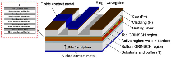
Figure 5.
Three-dimensional structure of the (110)-oriented compressed strain QW DFB laser.
The transmission process of optical signals can be modeled using the nonlinear Schrödinger equation [26], which can be solved efficiently by the split-step method [27,28]. The performance of a 10 Gbps optical transmission system operating at 1577 nm was numerically investigated. The simulation employed a standard G.652.D single-mode fiber (SMF) with characteristic parameters of 0.2 dB/km of attenuation and 18 ps/(nm·km) of dispersion at the operating wavelength. Given the short-haul nature of the proposed transmission system, both fiber nonlinear effects and higher-order dispersion terms were excluded from the numerical model. The fiber transmission characteristics of the directly modulated DFB laser signal were numerically investigated using the theoretical model presented in Appendix A, with system parameters specified in Table 2.
Table 2.
Simulation parameters for the DFB laser.
Figure 6a shows the calculated L-I curve with the (001)- and (110)-oriented DFB laser. The threshold current of the (110) crystal-oriented QW laser is reduced to 10 mA from 12 mA in the (001) crystal orientation, and the slope efficiency is basically the same. Figure 6b shows the simulated spectrum of the (110) crystal-to-substrate-grown DFB laser, which has a center wavelength at 1577 nm and has a good side-mode suppression ratio (SMSR). The obtained non-return-to-zero (NRZ) eye diagrams are shown in Figure 7b,d for the (001) and (110) crystal orientations of the DFB laser. Figure 7a,c show the bias current of the active part and the intensity of light emitted by the directly modulated DFB laser. It is found that DFB lasers with (110)-oriented quantum wells exhibit significantly improved eye-opening performance, thus enabling error-free bit rate transmission.
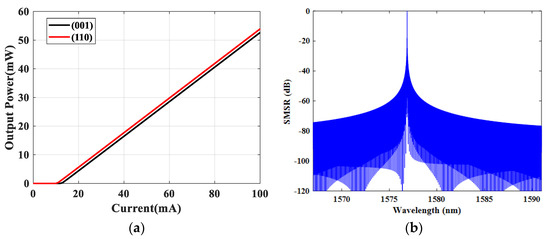
Figure 6.
(a) Calculated L-I curve with (001)- and (110) -oriented DFB laser. (b) The simulated spectra of the (110) substrate-grown DFB laser.
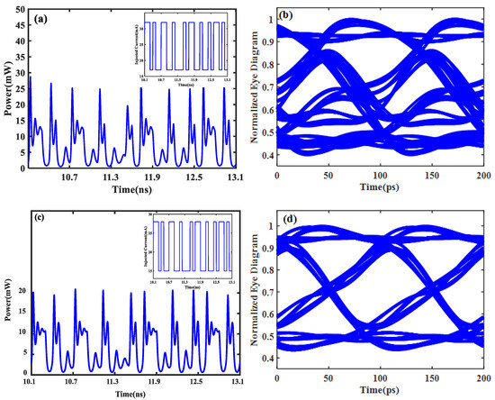
Figure 7.
Injected current signal and optical signal waveform for (a) (001) and (c) (110); eye diagrams of the 1577 nm 10 Gbps optical signal after 20 km for (b) (001) (LEF = 2.434) and (d) (110) (LEF = 1.408).
4. Conclusions
Based on the multi-band k.p theory, we investigate the optical gain characteristics of a AlGaInAs-InP strain QW with a (110) crystal orientation. The simulation results show that the LEF of QW lasers grown on (110)-oriented substrates is reduced by 28.3% and 42.1% compared with that of (001)-oriented QW lasers at gain thresholds of 500 cm−1 and 2000 cm−1, respectively. According to the simulation results of large-signal eye diagrams, the (110)-oriented DFB laser is capable of achieving 20 km of high-quality signal transmission in a 10 Gbps optical communication system. In the future, we will continue to optimize the model and carry out the experimental verification of the simulation results in this paper. Secondly, quantum dot lasers with different crystal orientations and strains will be an interesting research direction.
Author Contributions
Conceptualization, J.L.; Software, J.L.; Validation, M.H.; Formal analysis, J.L. and M.H.; Investigation, X.S.; Resources, X.S.; Data curation, Y.L.; Writing—original draft, J.L. and M.H.; Writing—review & editing, X.S., Y.L. and K.Z.; Visualization, J.L. All authors have read and agreed to the published version of the manuscript.
Funding
This research was funded by Zhejiang Provincial Key Technologies R&D Project (2024SJCZX0039), National Natural Science Foundation of China (62405017) and Fundamental Research Funds for the Central Universities (2025JBZX007).
Institutional Review Board Statement
Not applicable.
Informed Consent Statement
Informed consent was obtained from all subjects involved in the study.
Data Availability Statement
The data underlying the results presented in this paper are not publicly available at this time but may be obtained from the authors upon reasonable request.
Conflicts of Interest
The authors declare no conflict of interest.
Appendix A
The propagation dynamics of optical pulses in fiber systems are governed by the nonlinear Schrödinger equation, which describes the evolution of the slowly varying field envelope [26]:
where is the low-varying envelope of the optical field, is the fiber loss, is the second-order dispersion, is the third-order dispersion, and the fiber nonlinear parameters and are the imaginary unit.
Dynamic behavior of DFB lasers can be numerically investigated using the one-dimensional traveling wave model (TWM) [29]:
where and denote the slowly varying complex amplitudes for forward and backward wave propagation, respectively. is the optical confinement factor, is the photon density distribution, is the nonlinear gain suppression coefficient, is the phase detuning factor, is the internal loss, and is the grating coupling coefficient.
References
- Matsui, Y.; Schatz, R.; Che, D.; Khan, F.; Kwakernaak, M.; Sudo, T. Low-chirp isolator-free 65-GHz-bandwidth directly modulated lasers. Nat. Photonics 2021, 15, 59–63. [Google Scholar] [CrossRef]
- Verbist, J.; Verplaetse, M.; Srivinasan, S.; De Heyn, P.; De Keulenaer, T.; Pierco, R.; Vaernewyck, R.; Vyncke, A.; Absil, P.; Torfs, G.; et al. First real-time 100-Gb/s NRZ-OOK transmission over 2 km with a silicon photonic electro-absorption modulator. In Proceedings of the Optical Fiber Communication Conference, Los Angeles, CA, USA, 19–23 March 2017; Optica Publishing Group: Washington, DC, USA; p. Th5C-4. [Google Scholar]
- Kobayashi, W.; Ito, T.; Yamanaka, T.; Fujisawa, T.; Shibata, Y.; Kurosaki, T.; Kohtoku, M.; Tadokoro, T.; Sanjoh, H. 50-Gb/s direct modulation of a 1.3-μm InGaAlAs-based DFB laser with a ridge waveguide structure. IEEE J. Sel. Top. Quantum Electron. 2013, 19, 1500908. [Google Scholar] [CrossRef]
- Uomi, K. A Tutorial at OFC 2019: Ultra High-Speed Quantum-Well Semiconductor Lasers. In Proceedings of the 2019 Optical Fiber Communications Conference and Exhibition (OFC), San Diego, CA, USA, 3–7 March 2019; pp. 1–61. [Google Scholar]
- Kanazawa, S.; Yamazaki, H.; Nakanishi, Y.; Ueda, Y.; Kobayashi, W.; Muramoto, Y.; Ishii, H.; Sanjoh, H. 214-Gb/s 4-PAM operation of flip-chip interconnection EADFB laser module. J. Light. Technol. 2016, 35, 418–422. [Google Scholar] [CrossRef]
- Lange, S.; Wolf, S.; Lutz, J.; Altenhain, L.; Schmid, R.; Kaiser, R.; Schell, M.; Koos, C.; Randel, S. 100 GBd intensity modulation and direct detection with an InP-based monolithic DFB laser Mach–Zehnder modulator. J. Light. Technol. 2018, 36, 97–102. [Google Scholar] [CrossRef]
- Billia, L.; Zhu, J.; Ranganath, T.; Bour, D.P.; Corzine, S.W.; Hofler, G. 40-Gb/s EA modulators with wide temperature operation and negative chirp. IEEE Photonics Technol. Lett. 2005, 17, 49–51. [Google Scholar] [CrossRef]
- Nakahara, K.; Tsuchiya, T.; Kitatani, T.; Shinoda, K.; Taniguchi, T.; Kikawa, T.; Aoki, M.; Mukaikubo, M. 40-Gb/s Direct Modulation With High Extinction Ratio Operation of 1.3-µm InGaAlAs Multiquantum Well Ridge Waveguide Distributed Feedback Lasers. IEEE Photonics Technol. Lett. 2007, 19, 1436–1438. [Google Scholar] [CrossRef]
- Otsubo, K.; Matsuda, M.; Okumura, S.; Uetake, A.; Ekawa, M.; Yamamoto, T. Low-driving-current high-speed direct modulation up to 40 Gb/s using 1.3-μm semi-insulating buried-heterostructure AlGaInAs-MQW distributed reflector (DR) lasers. In Proceedings of the Optical Fiber Communication Conference, San Diego, CA, USA, 22–26 March 2009; p. OThT6. [Google Scholar]
- Liu, G.; Zhao, G.; Zhang, G.; Liu, Y.; Lu, Q.; Guo, W. Experimental demonstration of directly modulated DFB lasers with negative chirp over wide temperature operation. J. Light. Technol. 2020, 38, 3663–3669. [Google Scholar] [CrossRef]
- Hakki, B.W. Evaluation of transmission characteristics of chirped DFB lasers in dispersive optical fiber. J. Light. Technol. 1992, 10, 964–970. [Google Scholar] [CrossRef]
- Suematsu, Y.; Adams, A.R. Handbook of Semiconductor Lasers and Photonic Integrated Circuits; Chapman & Hall: Boca Raton, FL, USA, 1994. [Google Scholar]
- Warm, S.; Bunge, C.-A.; Wuth, T.; Petermann, K. Electronic dispersion precompensation with a 10-Gb/s directly modulated laser. IEEE Photonics Technol. Lett. 2009, 21, 1090–1092. [Google Scholar] [CrossRef]
- Matsui, Y.; Mahgerefteh, D.; Zheng, X.; Liao, C.; Fan, Z.; McCallion, K.; Tayebati, P. Chirp-managed directly modulated laser (CML). IEEE Photonics Technol. Lett. 2006, 18, 385–387. [Google Scholar] [CrossRef]
- Coldren, L.A.; Corzine, S.W.; Mashanovitch, M.L. Diode Lasers and Photonic Integrated Circuits; John Wiley & Sons: Hoboken, NJ, USA, 2012. [Google Scholar]
- Yamanaka, T.; Yoshikuni, Y.; Yokoyama, K.; Lui, W.; Seki, S. Theoretical study on enhanced differential gain and extremely reduced linewidth enhancement factor in quantum-well lasers. IEEE J. Quantum Electron. 1993, 29, 1609–1616. [Google Scholar] [CrossRef]
- Liu, J.; Li, J.; Xi, Y.; Li, X.; Ke, C.; Wang, Y.; Fu, Z. L-band directly modulated laser for 10G PONs. In Proceedings of the 2016 Progress in Electromagnetic Research Symposium (PIERS), Shanghai, China, 8–11 August 2016; p. 2718. [Google Scholar]
- Arakawa, Y.; Yariv, A. Theory of gain, modulation response, and spectral linewidth in AlGaAs quantum well lasers. IEEE J. Quantum Electron. 2003, 21, 1666–1674. [Google Scholar] [CrossRef]
- Yamanaka, T.; Yoshikuni, Y.; Lui, W.; Yokoyama, K.; Seki, S. Theoretical analysis of extremely small linewidth enhancement factor and enhanced differential gain in modulation-doped strained quantum-well lasers. Appl. Phys. Lett. 1993, 62, 1191–1193. [Google Scholar] [CrossRef]
- Ohtoshi, T.; Kuroda, T.; Niwa, A.; Tsuji, S. Dependence of optical gain on crystal orientation in surface-emitting lasers with strained quantum wells. Appl. Phys. Lett. 1994, 65, 1886–1887. [Google Scholar] [CrossRef]
- Li, J.; Gao, F.; Zhao, J. Active Region Design With Different Crystal Orientations for High-Speed DFB Laser. IEEE Photonics J. 2023, 16, 1–8. [Google Scholar] [CrossRef]
- Piprek, J.; Abraham, P.; Bowers, J.E. Self-consistent analysis of high-temperature effects on strained-layer multiquantum-well InGaAsP-InP lasers. IEEE J. Quantum Electron. 2002, 36, 366–374. [Google Scholar] [CrossRef]
- Ahn, D. Optical gain of a quantum-well laser with non-Markovian relaxation and many-body effects. IEEE J. Quantum Electron. 1996, 32, 960–965. [Google Scholar] [CrossRef]
- Niwa, A.; Ohtoshi, T.; Kuroda, T. Orientation dependence of optical properties in long wavelength strained quantum-well lasers. IEEE J. Select. Top. Quantum Electron 1995, 1, 211–217. [Google Scholar] [CrossRef]
- Li, J.; Zhao, J.; Gao, F. Numerical investigation of optical and photoelectric properties for 850 nm VCSELs with arbitrary crystal orientation. Crystals 2022, 12, 1459. [Google Scholar] [CrossRef]
- Govind, P.A. Nonlinear Fiber Optics (Optics and Photonics); Academic Press: San Diego, CA, USA, 2001. [Google Scholar]
- Hardin, R.H. Applications of the split-step Fourier method to the numerical solution of nonlinear and variable coefficient wave equations. Siam Rev. 1973, 15, 423. [Google Scholar]
- Hancock, J. Jitter—Understanding it, measuring it, eliminating it part 1: Jitter fundamentals. High Freq. Electron. 2004, 4, 44–50. [Google Scholar]
- Li, X. Optoelectronic Devices: Design, Modeling, and Simulation; Cambridge University Press: Cambridge, UK, 2009. [Google Scholar]
Disclaimer/Publisher’s Note: The statements, opinions and data contained in all publications are solely those of the individual author(s) and contributor(s) and not of MDPI and/or the editor(s). MDPI and/or the editor(s) disclaim responsibility for any injury to people or property resulting from any ideas, methods, instructions or products referred to in the content. |
© 2025 by the authors. Licensee MDPI, Basel, Switzerland. This article is an open access article distributed under the terms and conditions of the Creative Commons Attribution (CC BY) license (https://creativecommons.org/licenses/by/4.0/).