Communication

Magnetic Field and Temperature Dual-Parameter Optical Fiber Sensor Based on Fe3O4 Magnetic Film

1
State Key Lab of Information Photonics and Optical Communications, Beijing University of Posts and Telecommunications, Beijing 100876, China
2
School of Integrated Circuit Science and Engineering, Beihang University, Beijing 100191, China
*
Author to whom correspondence should be addressed.
Photonics 2025, 12(7), 633; https://doi.org/10.3390/photonics12070633
Submission received: 30 April 2025 / Revised: 29 May 2025 / Accepted: 20 June 2025 / Published: 22 June 2025

Abstract

A dual-parameter optical fiber sensor for measuring the magnetic field and temperature based on the Fabry–Perot interferometer (FPI) and magnetic polymer film was proposed and designed, realizing dual-parameter measurement of temperature and the magnetic field. The sensor uses the excellent elasticity and thermal expansion coefficient of PDMS and the magnetostrictive effect of Fe3O4 magnetic polymer film to provide magnetic field and temperature detection while maintaining good reusability, achieving a magnetic field sensitivity and temperature sensitivity of 69 pm/mT and 390 pm/K, respectively. The sensor has the advantages of a low cost, a simple manufacturing process, good linearity, and a sensitive temperature response. It has broad application prospects in medicine, geography, aerospace, and other fields.

1. Introduction

Optical fiber magnetic field sensors have been widely used in navigation and positioning, vehicle detection, current sensing, space and geophysical research, etc., due to their significant advantages such as high sensitivity, miniaturized structure, anti-electromagnetic interference, and long-distance signal transmission, effectively making up for the technical shortcomings of traditional magnetic field sensors. In recent years, researchers have proposed a variety of optical fiber magnetic field sensor schemes based on diverse magnetic field sensing mechanisms and innovative structural designs [1]. According to the combination of optical fiber and magnetic material, these sensors can be divided into the magnetic composite material type [2,3,4,5,6], magnetostrictive material type [7,8,9,10,11], magnetofluid type [12,13,14,15,16,17,18,19,20,21,22,23,24,25,26,27], and other categories. According to the type of optical fiber used or the sensing principle, these sensors can be divided into fiber Bragg grating [3,7], fiber interferometers [6], photonic crystal fiber [17,18], antiresonant fiber [22], and other types. In addition, many new materials and structures based on the refractive index principle have been proposed [28,29], providing more new possibilities for future magnetic field sensors.
Among the many optical fiber magnetic field sensors, magnetofluid-type and magnetostrictive material-type sensors have become research hotspots due to their unique performance advantages. In 2015, Zheng et al. first proposed a magnetic field sensor based on magnetic fluid and a fiber mode interferometer [25]. The sensor wrapped the magnetic fluid in the conical region of the tapered single-mode optical fiber, used the principle that the refractive index of the magnetic fluid changes due to magnetic field changes, monitored the wavelength drift of the transmission spectrum, and achieved a sensitivity of up to 29.3 pm/mT. Compared with traditional FP sensors, this sensor is simple to make and low in cost. However, due to the characteristics of the fluid itself, it still has problems such as a limited magnetic field detection range and decreased sensitivity after the magnetic fluid settles. In 2022, Jun et al. developed a sensor based on fiber Bragg grating (FBG) and magnetostrictive composite material [10]. The sensor used a mixture of Terfenol-D and epoxy resin to coat the FBG, achieving a sensitivity of 9.83 pm/mT and showing good repeatability. However, the sensor had problems such as high process requirements and low magnetic field sensitivity. In 2024, Li et al. proposed an innovative flexible magnetic field sensor combining a Michelson interferometer and PDMS-based optical fiber [4]. The optical fiber magnetic field sensor consisted of a 500 μm PDMS core and 150 μm PDMS/Fe3O4 composite cladding, with a sensitivity of −62.8 pm/mT. Although the sensor has high sensitivity, its manufacturing process is complex. At present, the field of optical fiber magnetic field sensing urgently needs a magnetic field sensor with a simple manufacturing method, high sensitivity, and long-term stable sensitivity.
The combination of PDMS and magnetic materials has shown significant potential in the field of magnetic field detection. PDMS can be used as an ideal flexible substrate material due to its high flexibility, optical transparency and chemical stability. By combining it with magnetic nanoparticles, an intelligent magnetic composite material with magnetic field response characteristics can be constructed. Therefore, this paper designs and implements a new type of optical fiber sensor based on PDMS and Fe3O4 magnetic polymer. The outer PDMS film wraps the inner magnetic polymer film to ensure stability of the structure. When the external magnetic field changes, only the refractive index and cavity length of the inner magnetic polymer film change. When the temperature changes, the shapes of both the magnetic polymer film and the non-magnetic polymer film will change. This design not only has the advantages of a simple manufacturing process and low cost but can also realize dual-parameter measurement of the magnetic field and temperature. At the same time, it effectively solves key problems, such as particle sedimentation and limited large-scale magnetic field monitoring in magnetic fluid sensors, and provides new ideas for the practical application of high-performance optical fiber magnetic field sensors.

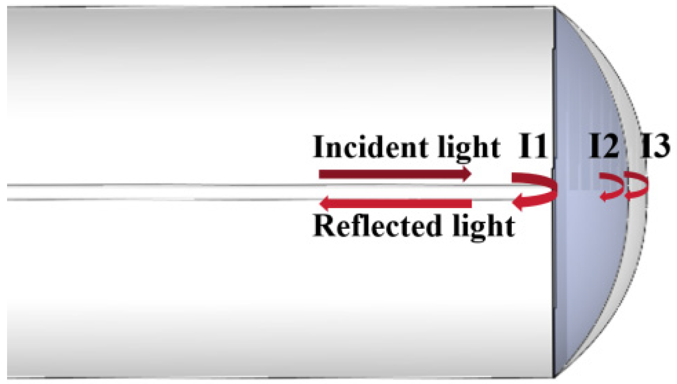
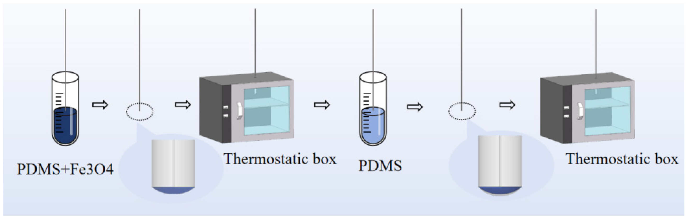
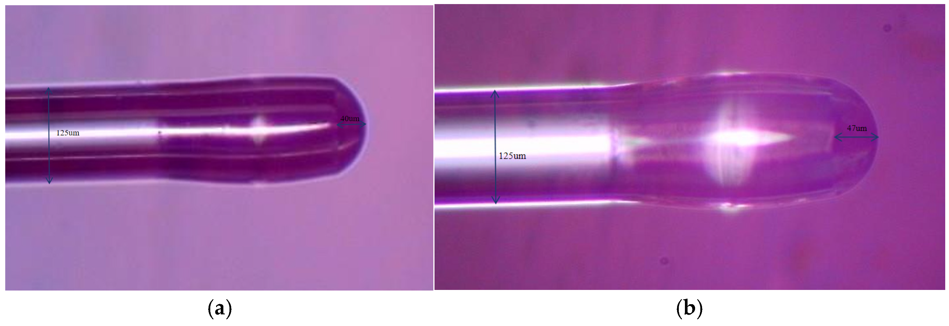
2. Sensor Fabrication and Principle

The structure of the sensor is shown in Figure 1. The three reflective surfaces are single-mode optical fiber, magnetic polymer film, formed by mixing Fe3O4 and PDMS and curing in an incubator, and cured PDMS film. When light enters the magnetic polymer film from the single-mode optical fiber, the first reflection occurs due to the different refractive indices of the two. The transmitted light is reflected for the second time when passing through the magnetic polymer film and the PDMS film. The remaining light propagates through the PDMS and reflects from the interface between the PDMS and the air.
According to the working principle of FPI, the total reflected light intensity IFP of the sensor is expressed as [30]:
I F P = I 1 + I 2 + I 3 + 2 I 1 I 2 cos ( φ 1 ) + 2 I 2 I 3 cos ( φ 2 ) + 2 I 1 I 3 cos ( φ 1 + φ 2 )
where I 1 , I 2 , and I 3 are the reflected light intensities from the interfaces of single-mode fiber to magnetic polymer film, magnetic polymer film to PDMS film, and PDMS film to air. φ 1 and φ 2 are the phase differences generated by magnetic polymer and PDMS film, respectively, which can be defined as
φ 1 = 4 π n 1 λ L 1 , φ 2 = 4 π n 2 λ L 2
where L 1 and L 2 represent the lengths of the magnetic polymer and the non-magnetic polymer, respectively, and the corresponding refractive indices are n 1 and n 2 . λ is the wavelength of the incident light. In the absence of a magnetic field, the magnetic moments of the Fe3O4 nanoparticles in the PDMS-based magnetic hemispherical polymer film are randomly distributed. When the sensing probe is placed in a magnetic field environment, the Fe3O4 nanoparticles are magnetized, and the direction of their magnetic moments gradually aligns with the direction of the external magnetic field, causing the refractive index of the magnetic polymer film to change. At the same time, the external magnetic field will induce the magnetostrictive deformation effect of the PDMS-based composite film and further change the optical path difference by regulating the cavity length L of the Fabry–Perot interferometer. This dual modulation effect of the magnetic field on the refractive index and cavity length causes a significant change in the intensity distribution of the light reflected by the optical fiber probe. In addition, when the ambient temperature changes, the refractive index and shape of the magnetic and non-magnetic polymer films will change due to the thermal expansion effect, thereby affecting the interference spectrum characteristics of the probe.
The fabrication process of this structure is shown in Figure 2. The specific steps are as follows: First, use a high-precision fiber cleaver (Fujikura CT-30, Tokyo, Japan) to cut the end face of the single-mode optical fiber (SMF-28) to ensure that the end face roughness is less than 20 nm. The cut optical fiber is fixed vertically on a three-dimensional electric translation stage (PI M-111.1 DG, Karlsruhe, Germany, precision 0.1 μm). Take PDMS prepolymer (Dow Corning Sylgard 184, Midland, MI, USA) base glue and curing agent in a mass ratio of 10:1 and put them into an ultrasonic oscillator for dispersion for 30 min to ensure that the base glue and curing agent are fully mixed. Use a rubber-tipped dropper to take 9.5 g of the base glue and curing agent mixed solution and put it in a test tube, and take another 0.5 g of Fe3O4 powder (average particle size 10 nm) and mix it with the base glue and curing agent solution. Place the magnetic mixed solution in an ultrasonic oscillator and disperse it for 30 min until the solution is a uniform gray-black suspension, and the magnetic polymer solution is obtained. Take a small amount of the magnetic mixed solution and place it in a test tube, fix the test tube on the translation stage, and let it stand for 15 min to eliminate bubbles. Then connect the optical path of the demodulator to the input end of the optical fiber. To ensure the smooth progression of the infiltration process, this experiment was carried out at a temperature of 20 °C ± 2 °C and a humidity of 40–60%RH. Set the vertical movement speed of the translation stage to 50 μm/s, and control the fiber end face to immerse in the magnetic PDMS liquid film at a constant rate. When the double-beam interference feature appears in the demodulator reflection spectrum, immediately pause the translation stage and keep it immersed for 60 s to ensure that the PDMS fully infiltrates the fiber end face. Then pull the optical fiber at a constant speed of 20 μm/s to form a magnetic PDMS sensitive layer with a thickness of about 40 ± 2 μm. Place the coated optical fiber probe in an incubator at 80 °C for one hour. Finally, follow the same steps to apply PDMS solution to the end of the probe and cure it to form a double-layer structure. The final thickness of the double-layer structure is 47 ± 2 μm. Figure 3 is a real shot of the final structure.

3. Experimental Results and Discussion

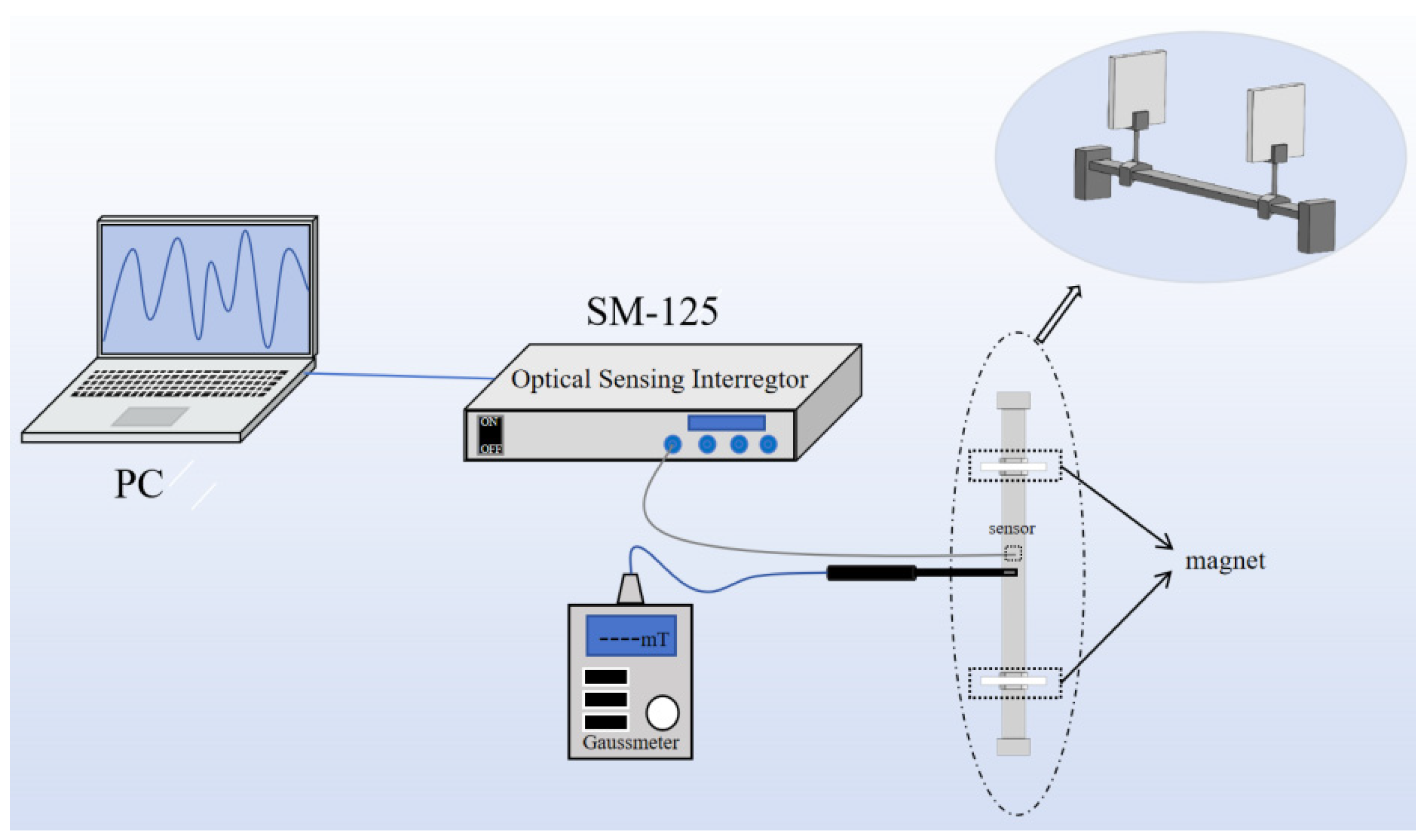
3.1. Magnetic Field Sensitivity Experiment

In order to test the sensitivity of this structure to the magnetic field, a magnetic field measurement device, as shown in Figure 4, was built. The device includes a fiber demodulator (SM-125, Tongwei Sensing, Beijing, China), a Gaussmeter (HT20, Hengtong Magnetic Technology Co., Ltd., Shanghai, China), two high-strength NdFeB magnets, and a slide rail (HYL60-300, Nishidun automation technology CO., Shenzhen, China). The fiber demodulator integrates a broadband light source with a wavelength range of 1510–1590 nm and a spectrum demodulation system with a full spectrum scanning frequency of 1 Hz and an accuracy of 1 pm. The demodulation system uses Fabry–Perot tunable filter technology to achieve high-precision wavelength selection and filter modulation and demodulation of the input optical signal and uses a signal processing system to analyze and demodulate the reflection spectrum. The fiber probe and the Gaussmeter probe are fixed between the two strong NdFeB magnets on the slide rail fixture. By adjusting the distance between the two NdFeB magnets, a uniform magnetic field with variable magnetic field strength is formed in the fiber probe and Gaussmeter probe area, and the size of the uniform magnetic field is measured by the Gaussmeter.
The measured experimental data are shown in Figure 5, and the step distance of the magnetic field intensity is 10 mT. It can be seen that the wavelength red-shifts when the magnetic field intensity gradually increases from 0 mT to 50 mT. The change in magnetic field intensity causes the shape and refractive index of the magnetic polymer film to change, and the reflection cavity length changes with the increase in magnetic field intensity. Since the outer layer is wrapped by PDMS film and is a flexible material, the polymer cavity will change at the same time as the PDMS cavity. The interference peak moves from 1544.01 nm to 1547.49 nm in the long wavelength direction, where R2 is the fit. According to the fitting curve, the sensitivity is 69 pm/mT, and R2 is 0.9938. The data show that the curve fits well.

3.2. Temperature Sensing Experiment

The temperature measurement device is shown in Figure 6. The magnetic probe is placed in the temperature box, and the other end of the optical fiber is connected to the optical fiber demodulator. The reflection spectrum is viewed in real time through the computer, and the spectrum is saved when necessary. The temperature in the temperature box can be viewed in real time through the temperature box LCD screen.
The measured experimental data are shown in Figure 7. The temperature step distance is 10 °C. When the temperature rises from 20 °C to 70 °C, the wavelength red-shifts, and the trough shifts from 1544.015 nm to 1563.575 nm. According to the data fitting curve, the temperature sensitivity is 390 pm/K. The fitting degree is 0.9849, which is a good fit.
To verify the repeatability, we made six sensors according to the same steps as above and experimentally measured the magnetic field sensitivity and temperature sensitivity of the six sensors. The test results are shown in Figure 8. The magnetic field sensitivity of the six sensors is 64.5 ± 4.16 pm/mT. The repeatability measurement results show that the fluctuation is within a reasonable range, which indicates that the sensor is repeatable.
In order to prove that the sensor has long-term stability, we selected optical fiber No. 1 as the sample for long-term stability measurement. The stability experiment maintained relatively stable temperature and humidity (TE: 20 °C ± 2 °C, RH: 40 ± 5%), and the magnetic field sensitivity and temperature sensitivity of optical fiber No. 1 were measured six times at intervals of 24 h. The experimental results are shown in Figure 9. The long-term magnetic field sensitivity of the sensor is 68.5 ± 0.71 pm/mT, and the long-term temperature sensitivity is 391 ± 5.5 pm/K. The long-term stability results show that the errors of magnetic field sensitivity and temperature sensitivity are both less than 2%, which indicates that the sensor has long-term stability.
Cross-sensitivity can be quantitatively characterized by the sensitivity parameter ratio, and its mathematical expression is
K T B = S T S B
where KT→B is the cross-sensitivity of temperature to magnetic field measurement, ST is the temperature sensitivity coefficient, and SB is the magnetic field sensitivity coefficient. The cross-sensitivity analysis shows that temperature is the main error source that interferes with magnetic field measurement. From the mathematical expression of cross-sensitivity, we know that KT→B ≈ 6 mT/K.
Table 1 summarizes the sensing performance of various temperature and magnetic field measurement structures. Notably, the proposed FP cavity integrated with magnetic polymer film exhibits a significantly broader detectable magnetic field range while maintaining competitive temperature and magnetic field sensitivities (69 pm/mT and 390 pm/K, respectively). Moreover, this structure features a simple fabrication process with minimal technical requirements, making it highly attractive for practical applications in magnetic field and temperature sensing.

4. Conclusions

This study proposes a new fiber-optic sensor based on a double Fabry–Perot (FP) cavity structure of Fe3O4 magnetic polymer/PDMS composite film, which realizes high-sensitivity simultaneous measurement of magnetic field and temperature dual parameters. The sensor exhibits a magnetic field sensitivity of 69 pm/mT in the magnetic field range of 0–50 mT and a temperature sensitivity of 390 pm/K in the temperature range of 20–70 °C through the synergistic effect of the magnetostrictive effect of Fe3O4 nanoparticles and the thermal expansion characteristics of PDMS, and both have excellent linearity (R2 > 0.98). The layered FP cavity structure design effectively overcomes the limitations of magnetic fluid sedimentation problems and complex preparation processes in traditional sensors. However, the sensor also has some problems. For example, the magnetic field sensitivity is still far behind that of the sensor made of Terfenol-D material, which is mainly due to the low magnetostrictive properties of Fe3O4. In response to these challenges, future research will focus on developing Fe3O4-TbDyFe hybrid materials to enhance strain transfer effects, using microfluidic spinning technology to achieve precise control of submicron film thickness, and introducing machine learning algorithms to compensate for nonlinear temperature responses. These research findings not only confirm the excellent performance of current sensors under conventional conditions but, more importantly, reveal the fundamental limitations brought about by the intrinsic properties of materials and point out key optimization directions and technical paths for the development of the next generation of intelligent fiber-optic sensors.

Author Contributions

Conceptualization, S.X. and H.Z.; methodology, S.X. and H.Z.; validation, S.X., H.Z., Z.C., Y.L., R.Z. and Z.Z.; writing—original draft preparation, S.X.; writing—review and editing, S.X., H.Z., Z.C., Y.L., R.Z. and Z.Z.; funding acquisition, H.Z. All authors have read and agreed to the published version of the manuscript.

Funding

This work was supported by the National Natural Science Foundation of China (62375026), Fund of the State Key Laboratory of IPOC (BUPT) (IPOC2024ZT06) and the BUPT Excellent Ph.D. Students Foundation (CX20241032).

Institutional Review Board Statement

Not applicable.

Informed Consent Statement

Not applicable.

Data Availability Statement

Data are contained within the article.

Conflicts of Interest

The authors declare no conflicts of interest.

References

  1. Liu, C.; Shen, T.; Wu, H.B.; Feng, Y.; Chen, J.-J. Applications of magneto-strictive, magneto-optical, magnetic fluid materials in optical fiber current sensors and optical fiber magnetic field sensors: A review. Opt. Fiber Technol. 2021, 65, 102634. [Google Scholar] [CrossRef]
  2. Stasiewicz, K.A.; Jakubowska, I.; Moś, J.E.; Marć, P.; Paczesny, J.; Zbonikowski, R.; Jaroszewicz, L.R. Optical properties of a tapered optical fiber coated with alkanes doped with Fe3O4 nanoparticles. Sensors 2022, 22, 7801. [Google Scholar] [CrossRef] [PubMed]
  3. Wang, S.F.; Chiang, C.C. A Micro Rectangular-Shaped Long-Period Fiber Grating Coated with Fe3O4 Nanoparticle Thin Overlay for Magnetic Sensing. Materials 2015, 8, 7074–7083. [Google Scholar] [CrossRef]
  4. Li, L.; Wang, X.; Jiang, C.; Zhou, L.; Cong, Z.; Sun, Y.; Dong, T.; Liu, X.; Chen, P. A novel flexible optical fiber magnetic field sensor based on integrated Fe3O4 nanoparticles. Opt. Fiber Technol. 2024, 87, 103904. [Google Scholar] [CrossRef]
  5. Song, J.; Sun, S.; Jiang, C.; Chen, H.; Zhu, X.; Ren, J.; Wang, S. A tapered multicore fiber sensor for measuring temperature and magnetic field. Opt. Fiber Technol. 2023, 80, 103384. [Google Scholar] [CrossRef]
  6. Li, Y.; Xie, F.; Jia, L.; Li, G.; Liang, L. A microfiber interferometer magnetic sensor with magnetostrictive polymer composite. J. Mod. Opt. 2025, 72, 201–206. [Google Scholar] [CrossRef]
  7. Wu, B.; Chen, H.; Xiao, S.; Yin, B.; Wang, M.; Zhao, X.; Yan, F. Sensitivity Enhancement for magnetic field sensor using an optoelectronic oscillator based on fiber Bragg grating Fabry-Perot Cavity with acrylate-adhesive. IEEE Sens. J. 2024, 24, 19117–19124. [Google Scholar] [CrossRef]
  8. Deng, L.; Jiang, C.; Gao, J.; Hu, C.; Li, L.; Cao, T.; Li, H.; Sun, S.; Huang, H. Ultrasensitive magnetic field sensor based on Fabry–Perot interferometer and magnetostrictive material. IEEE Sens. J. 2023, 23, 30444–30450. [Google Scholar] [CrossRef]
  9. Chen, X.; Wu, S.; Li, N.; Liu, L.; He, S. Passive temperature-compensated fiber Fabry-Perot magnetic field sensor. Opt. Express 2025, 33, 449–461. [Google Scholar] [CrossRef]
  10. Peng, J.; Zhang, S.; Jia, S.; Kang, X.; Yu, H.; Yang, S.; Wang, S.; Yang, Y. A highly sensitive magnetic field sensor based on FBG and magnetostrictive composite with oriented magnetic domains. Measurement 2022, 189, 110667. [Google Scholar] [CrossRef]
  11. Zhu, M.; Gao, P.; Cai, S.; Zhang, N.; Wu, B.; Liu, Y.; Yin, B.; Wang, M. High-Sensitivity Magnetic Field Sensor Based on an Optoelectronic Oscillator with a Mach-Zehnder Interferometer. Sensors 2025, 25, 1621. [Google Scholar] [CrossRef] [PubMed]
  12. Xu, R.; Niu, G.; Xue, Y.; Ke, C.; Deng, H.; Deng, S.; Chen, M.; Yuan, L. An all-optical vector magnetic field sensor based on magnetic fluid and side-polished hollow-core optical fiber. IEEE Sens. J. 2021, 21, 21410–21416. [Google Scholar] [CrossRef]
  13. Xia, J.; Wang, F.; Luo, H.; Wang, Q.; Xiong, S. A magnetic field sensor based on a magnetic fluid-filled FP-FBG structure. Sensors 2016, 16, 620. [Google Scholar] [CrossRef] [PubMed]
  14. Shi, F.; Bai, X.; Wang, F.; Pang, F.; Pu, S.; Zeng, X. All-fiber magnetic field sensor based on hollow optical fiber and magnetic fluid. IEEE Sens. J. 2016, 17, 619–622. [Google Scholar] [CrossRef]
  15. Li, Y.; Pu, S.; Zhao, Y.; Yao, T. Fiber-optic magnetic field sensing based on microfiber knot resonator with magnetic fluid cladding. Sensors 2018, 18, 4358. [Google Scholar] [CrossRef]
  16. Zhang, Y.; Zhu, N.; Gao, P.; Zhao, Y. Magnetic field sensor based on ring WGM resonator infiltrated with magnetic fluid. J. Magn. Magn. Mater. 2020, 493, 165701. [Google Scholar] [CrossRef]
  17. Zu, P.; Chan, C.C.; Lew, W.S.; Hu, L.; Jin, Y.; Liew, H.F.; Chen, L.H.; Wong, W.C.; Dong, X. Temperature-insensitive magnetic field sensor based on nanoparticle magnetic fluid and photonic crystal fiber. IEEE Photonics J. 2012, 4, 491–498. [Google Scholar]
  18. Yan, L.; Wang, Q.; Yin, B.; Xiao, S.; Li, H.; Wang, M.; Liu, X.; Wu, S. Research on simultaneous measurement of magnetic field and temperature based on petaloid photonic crystal fiber sensor. Sensors 2023, 23, 7940. [Google Scholar] [CrossRef]
  19. Zhang, J.; Qiao, X.; Yang, H.; Wang, R.; Rong, Q.; Lim, K.S.; Ahmad, H. All-fiber magnetic field sensor based on tapered thin-core fiber and magnetic fluid. Appl. Opt. 2017, 56, 200–204. [Google Scholar] [CrossRef]
  20. Song, B.; Miao, Y.; Lin, W.; Zhang, H.; Liu, B.; Wu, J.; Liu, H.; Yan, D. Loss-based magnetic field sensor employing hollow core fiber and magnetic fluid. IEEE Photonics Technol. Lett. 2014, 26, 2283–2286. [Google Scholar] [CrossRef]
  21. Guo, J.; Wang, W.; Dong, L.; Li, X.; Guo, Z.; Du, X.; Zhang, J. Highly sensitive magnetic field sensor based on few mode fiber interferometry. IEEE Sens. J. 2024, 24, 16179–16187. [Google Scholar] [CrossRef]
  22. Gao, R.; Lu, D.F.; Cheng, J.; Jiang, Y.; Jiang, L.; Ye, J.S.; Qi, Z.M. Magnetic fluid-infiltrated anti-resonant reflecting optical waveguide for magnetic field sensing based on leaky modes. J. Light. Technol. 2016, 34, 3490–3495. [Google Scholar] [CrossRef]
  23. Zhang, Q.; Liu, H.; Fu, R.; Li, B.; Yan, X.; Zhang, X.; Wang, F.; Cheng, T. High sensitivity surface plasmon resonance magnetic field sensor based on Au/gold nanoparticles/magnetic fluid in the hollow core fiber. IEEE Sens. J. 2023, 23, 12899–12905. [Google Scholar] [CrossRef]
  24. Tian, P.; Guan, C.; Ye, P.; Cheng, T.; Yang, J.; Zhu, Z.; Shi, J.; Yang, J.; Yuan, L. Dual mode interference magnetic-field sensor based on hollow suspended-core fiber. IEEE Photonics Technol. Lett. 2021, 34, 43–46. [Google Scholar] [CrossRef]
  25. Zheng, Y.; Dong, X.; Chan, C.C.; Shum, P.P.; Su, H. Optical fiber magnetic field sensor based on magnetic fluid and microfiber mode interferometer. Opt. Commun. 2015, 336, 5–8. [Google Scholar] [CrossRef]
  26. Yin, J.; Ruan, S.; Liu, T.; Jiang, J.; Wang, S.; Wei, H.; Yan, P. All-fiber-optic vector magnetometer based on nano-magnetic fluids filled double-clad photonic crystal fiber. Sens. Actuators B Chem. 2017, 238, 518–524. [Google Scholar] [CrossRef]
  27. Duan, S.; Pu, S.; Lin, X.; Liu, W.; Hao, Z.; Zhang, C.; Fu, J.; Han, S. Enhanced sensitivity of temperature and magnetic field sensor based on FPIs with Vernier effect. Opt. Express 2023, 32, 275–286. [Google Scholar] [CrossRef]
  28. Zeng, Z.; Liu, H.; Zhang, H.; Cheng, S.; Yi, Y.; Yi, Z.; Wang, J.; Zhang, J. Tunable ultra-sensitive four-band terahertz sensors based on Dirac semimetals. Photonics Nanostruct.-Fundam. Appl. 2025, 63, 101347. [Google Scholar] [CrossRef]
  29. Zeng, L.; Li, B.; Wen, R.; Zhang, X. Plasmonic sensor based on multi fano resonance in inverse T shape structure for detection of CO2 concentration. IEEE Photonics J. 2023, 15, 2201805. [Google Scholar] [CrossRef]
  30. Li, Z.; Tian, J.; Jiao, Y.; Sun, Y.; Yao, Y. Simultaneous measurement of air pressure and temperature using fiber-optic cascaded Fabry-Perot interferometer. IEEE Photonics J. 2018, 11, 7100410. [Google Scholar] [CrossRef]
  31. Luo, L.; Pu, S.; Dong, S.; Tang, J. Fiber-optic magnetic field sensor using magnetic fluid as the cladding. Sens. Actuators A Phys. 2015, 236, 67–72. [Google Scholar] [CrossRef]
  32. Su, G.H.; Shi, J.; Xu, D.G.; Zhang, H.W.; Xu, W.; Wang, Y.Y.; Feng, J.C.; Yao, J.Q. Simultaneous magnetic field and temperature measurement based on no-core fiber coated with magnetic fluid. IEEE Sens. J. 2016, 16, 8489–8493. [Google Scholar] [CrossRef]
  33. Wei, L.; Li, H.; Hu, T.; Fu, R.; Zhao, Y.; Cheng, T.; Yan, X. Magnetic field and temperature two-parameter sensor based on Mach-Zehnder interferometer and faraday rotation effect. IEEE Sens. J. 2023, 23, 14041–14048. [Google Scholar] [CrossRef]
  34. Ying, Y.; Hu, N.; Si, G.Y.; Xu, K.; Liu, N.; Zhao, J.Z. Magnetic field and temperature sensor based on D-shaped photonic crystal fiber. Optik 2019, 176, 309–314. [Google Scholar] [CrossRef]
Figure 1. Schematic diagram of the structure of optical fiber magnetic field sensor.
Photonics 12 00633 g001
Figure 2. Schematic diagram of the structure fabrication process.
Photonics 12 00633 g002
Figure 3. (a) Microscope image of a sensor structure coated only with a magnetic polymer film; (b) microscope image of a sensor structure coated with a magnetic polymer and a nonmagnetic film.
Photonics 12 00633 g003
Figure 4. Schematic diagram of magnetic field measurement device.
Photonics 12 00633 g004
Figure 5. (a) Interference spectra under different magnetic fields; (b) interference peak fitting results.
Photonics 12 00633 g005
Figure 6. Temperature measuring device.
Photonics 12 00633 g006
Figure 7. (a) Interference spectra at different temperatures; (b) Interference peak fitting results.
Photonics 12 00633 g007
Figure 8. Magnetic field sensitivity and temperature sensitivity data of six sensors.
Photonics 12 00633 g008
Figure 9. Stability test.
Photonics 12 00633 g009
Table 1. Sensing performance of various temperature and magnetic field measurement structures.
StructuresDetecting
Range
Magnetic Field
Sensitivity
Temperature
Sensitivity
Reference
SMS0–13 mT659 pm/mT−42 pm/K[31]
No-core
Fiber
2–14 mT74 pm/mT−247 pm/K[32]
FP-MZI0–15 mT19 pm/mT−846 pm/K[33]
Microfiber
interferometer
0–200 mT49 pm/mT\[6]
D-shaped PCF0–27 mT2100 pm/mT−1250 pm/K[34]
SMS-FP0–50 mT69 pm/mT390 pm/KThis work
Disclaimer/Publisher’s Note: The statements, opinions and data contained in all publications are solely those of the individual author(s) and contributor(s) and not of MDPI and/or the editor(s). MDPI and/or the editor(s) disclaim responsibility for any injury to people or property resulting from any ideas, methods, instructions or products referred to in the content.

