Article

Dual-Color and High-Energy X-Ray Kirkpatrick–Baez Microscope for Laser Plasma Research

1
Key Laboratory of Advanced Micro-Structured Materials, Ministry of Education, Tongji University, Shanghai 200092, China
2
School of Physics Science and Engineering, Tongji University, Shanghai 200092, China
3
Laser Fusion Research Center, China Academy of Engineering Physics, Mianyang 621900, China
4
State Key Laboratory of Plasma Physics, China Academy of Engineering Physics, Mianyang 621900, China
*
Authors to whom correspondence should be addressed.
Photonics 2025, 12(7), 630; https://doi.org/10.3390/photonics12070630
Submission received: 23 May 2025 / Revised: 17 June 2025 / Accepted: 18 June 2025 / Published: 20 June 2025
(This article belongs to the Section Lasers, Light Sources and Sensors)

Abstract

:
High-energy X-ray diagnostic systems are crucial for understanding hotspot high-density area asymmetry, fuel mixing, and other phenomena in inertial confinement fusion. To meet the demand for hotspot electron temperature measurements, we developed a high-energy dual-channel Kirkpatrick–Baez microscope. This microscope is characterized by a dual high-energy response and high spatial resolution, enabling the observation of fine structures in high-density regions of a hotspot. Spectral drift was effectively mitigated by optimizing the grazing incidence angle, and the spatial and spectral domains were coupled through experimental alignment. Herein, we describe the optical design of the proposed microscope. Furthermore, we performed simulations and backlight imaging to validate the performance of the proposed system. The results show that the spatial resolution was better than 3 μm in the center and better than 6.5 μm in a field of view of 300 μm. The spectral response efficiencies at 11.4 and 17.48 keV were 7.41 × 10⁻⁸ and 5.77 × 10⁻⁸ sr, which deviate from the theoretical values by 3.01% and 6.79%, respectively.

1. Introduction

In laser inertial confinement fusion (ICF) [1,2], a capsule containing deuterium–tritium (D–T) fuel is compressed into a dense and hot plasma state of ~100 μm diameter in ~100 ps. A hotspot is formed at the peak compression. This hotspot radiates numerous X-rays containing spatiotemporal information. High-resolution X-ray imaging is an essential method for investigating temperature and density distributions [3,4], radiation asymmetry [5,6], and fuel mixing [7,8]. As the driving energy and implosion areal density increase, the ignition capsule exhibits more intense self-absorption of low-energy (<10 keV) X-rays [9]. Therefore, a high-energy (10–20 keV) response is required for hotspot imaging to achieve high penetration depth and detailed visualization in high-density regions. To determine the electron temperature and density distributions in the high-density regions of the hotspot, the intensity ratios of X-ray emission images at multiple energy points must be simultaneously measured [10]. Considering the spatial scale of the hotspot and the aiming accuracy of the object, a high-energy diagnostic system should have a field of view (FOV) greater than 200 µm and a spatial resolution better than 5 µm [11].
A variety of high-energy diagnostic devices have been explored in previous studies, including pinholes [12], compound refractive lenses (CRLs) [13], bent crystal [14], and the Kirkpatrick–Baez (KB) microscope [15]. The spatial resolution of a pinhole is limited to 10–20 μm due to diffraction effects. CRLs based on refractive imaging are known for their compact design and adjustable focal length, enabling micro-focusing in synchrotron radiation or free-electron lasers. However, their limitations in terms of chromatic aberrations and manufacturing challenges make them less suitable for monochromatic imaging of hotspots in ICF. The KB microscope [16,17] and bent crystals are two diagnostic devices widely used for monochromatic imaging in ICF, offering higher spatial resolution and light collection efficiency compared to pinhole imaging techniques. A toroidal crystal for backlighting Mo Kα1 characteristic lines (~17.48 keV) achieved a spatial resolution of 5–10 μm in a FOV larger than 1 mm. Bent crystal imaging does have the advantages of monochromaticity and large FOV but is constrained by fixed lattice constants and lower spatial resolution. The spatial resolution of the KB microscope can reach 3–5 µm, which is slightly superior to bent crystal imaging. Two diagnostic systems based on the KB microscope have been developed for hotspot electron temperature measurements. In 2021, simultaneous imaging at 6.4 and 9.6 keV was achieved using a dual-channel KB system that combines total-reflection KB mirrors and a planar mirror coated with a nonperiodic multilayer film [18]. In 2024, a four-color KB system coated with single-layer and periodic multilayer films was developed, enabling quasi-monoenergetic imaging at four energy points (4.51, 6.4, 8.04, and 9.67 keV) [19]. However, these systems were designed for low-energy X-rays; thus, they are ineffective for capturing X-ray emission images from dense plasmas.
The spectral resolution of a KB microscope can be improved by depositing a thin film on the reflector surface [20]. High-energy KB microscopes have rarely been reported, as there are challenges associated with the design and development of microscopes for operation at 10 keV or above. For high energies, high-Z-metal films are unsuitable because the grazing incidence angle is restricted to a very small critical angle [3]. Periodic multilayer coatings are usually employed for quasi-monochromatic imaging of high-energy X-rays. However, when the reflectivity is maintained at an acceptable level, the angular bandwidth of the periodic multilayer films decreases as the energy increases, which limits the FOV. In addition, at larger grazing incidence angles, the thickness of the multilayer coating at higher energy points can easily approach approximately 2 nm, leading to significant thickness errors during the coating process. For instance, for a W/Si periodic multilayer coating at a 17.48 keV energy point and a grazing incidence angle of 1°, an introduced thickness deviation of 0.1 nm can lead to a spectral drift of approximately 800 eV. The spectral drift due to deviations in film thickness is nonnegligible and can affect the accuracy of electron temperature measurements. This is a challenge in the design and fabrication of high-energy KB microscope films.
In this study, we developed a dual-color and high-energy KB microscope for hotspot electron temperature measurements. Spectral drift was suppressed by optimizing the grazing incidence angle and the periodic thickness of the multilayer films. Through optical element detection and experimental alignment, the spatial and spectral domains were precisely coupled. Herein, we discuss the optical design of the microscope and the multilayer design. Furthermore, we simulated the spectral distribution and response efficiency. Grid and resolution test card backlight imaging was conducted to validate the imaging performance of the proposed system and the response capability of the high-energy spectrum. The proposed microscope can provide valuable insights into the measurement of electron temperature and density in high-energy regions.

2. Optical Design

As shown in Figure 1a, the high-energy KB system comprises three spherically curved mirrors arranged in an orthogonal orientation, forming two imaging channels at the right-angle junctions of the mirrors corresponding to the 11.4 and 17.48 keV energy points. The one-dimensional (1D) imaging equation for each mirror is expressed as follows:
1 u + 1 v = 1 f = 2 R sin θ ,
where u and v are the object and image distances, respectively, f the focal length, R the radius, and θ the grazing incidence angle. The distance between the center of the mirror and the optical axis and the angle of inclination of the reflecting surface must be precisely selected to ensure high image quality. This was achieved by leaning the mirror’s reflective surface against an ultrasmooth polished quartz core, whose geometric size and surface tilt angle (relative to the optical axis) were machined to an accuracy of ±0.01 mm and 0.048 mrad, respectively. The KB mirror pairs were focused independently in two orthogonal directions. The 1D focusing diagrams are shown in Figure 1b,c. By rigidly rotating the KB mirrors around an object, the image position can be adjusted while satisfying the imaging relationship. For mirror M1, the relevant geometric relationships are as follows:
L = 2 u sin θ r + θ + 2 M u sin θ r θ ,
l = 2 u sin θ r + θ ,
where θr is the rotation angle, M is the magnification, L is the spacing between image points A1 and A2, and l is the center distance between mirrors M1 and M2. The detailed dimensional parameters of the cone core can be obtained from l, the mirror length, and the rotation angle. Because the rotation-induced tilt angle of the object plane is comparable to the grazing incidence angle, the resulting aberration is negligible. The optimized outgoing rays are nearly parallel, which prevents the effects of 1D or direct beams between channels on the two-dimensional (2D) image. The image interval between the two channels was set to 20 mm to match the precise position of the microstrip of the streak camera. Table 1 lists the optical parameters of the high-energy KB microscope. The three mirrors are all spherical mirrors made of silicon material with a radius of curvature of 40 m to achieve a symmetric dual-channel structure.

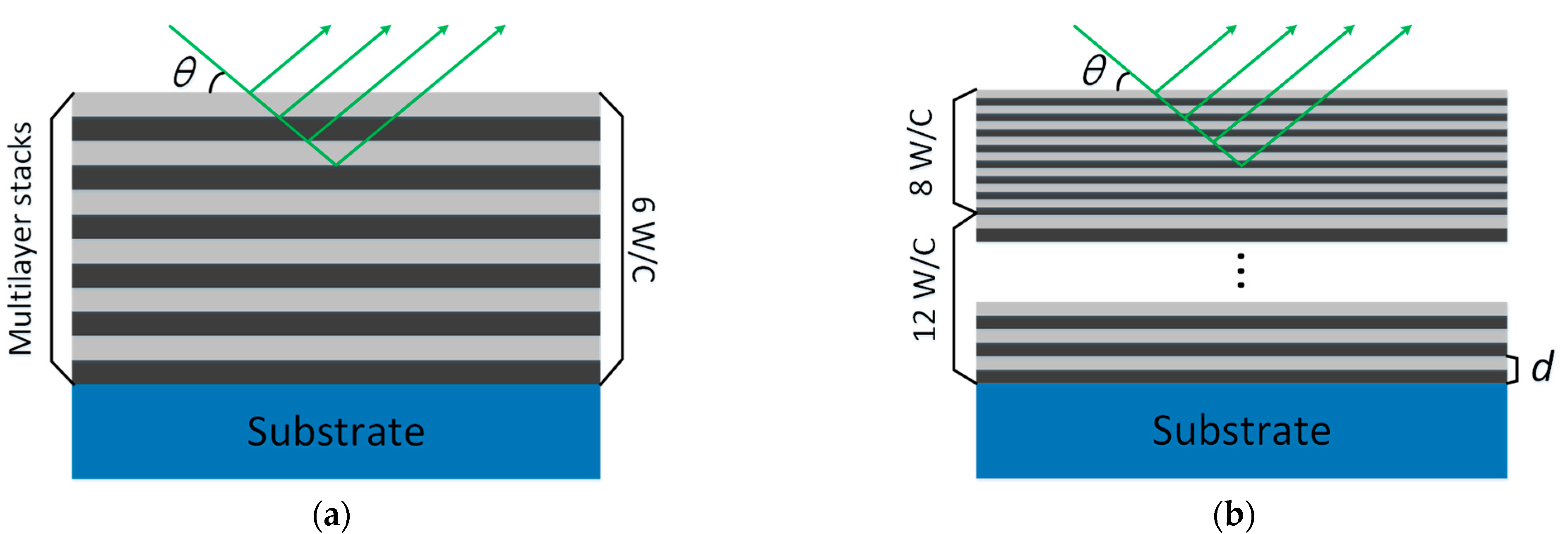
3. Multilayer Design

Because the plasma radiates a broad spectrum of X-rays, the response to the high-energy spectrum can be obtained by coating the mirror surface with periodic multilayers. Multilayer design requires consideration of the range of angular variations within the microscope aperture caused by the FOV and calculation of the necessary angular bandwidth of the multilayer. Periodic multilayer coatings can achieve a response at specific energy points and grazing incidence angles by alternately depositing two materials with high and low atomic numbers on the mirror surface. Therefore, X-ray multilayer coatings can be regarded as an artificial crystal with specific thickness and refractive index. When these reflected X-ray beams satisfy the interference condition (or Bragg condition), the resulting strong reflection intensity satisfies the Bragg equation [21]:
2 d sin θ = n λ ,
where d is the periodic thickness of the periodic multilayer, θ is the grazing incidence angle, λ is the wavelength, and n is the number of reflection stages. The size of the laser–plasma hotspot to be diagnosed was ~100 μm, and the effective FOV was set to ±150 μm considering the influence of the aiming error. The object FOV q (150 μm herein) and its resulting angular change Δθ satisfy the geometric relationship 2q = usinΔθ, where u is the object distance. To cover the required FOV, the angular bandwidth (FWHM) of the high-energy KB multilayer should exceed 0.09°.
The Lβ1 line of Au (11.4 keV) and Kα1 line of Mo (17.48 keV) were considered the working energy points of the high-energy KB microscope, and the optimized parameters of the multilayer films are listed in Table 2. As depicted in Figure 2a, at the energy point of 11.4 keV, a six-layer periodic multilayer composed of tungsten (W) and carbon (C) was deposited on the mirror substrate. The selection of W and C is driven by their high reflectivity, structural stability, and relatively mature fabrication processes. However, for the 17.48 keV energy point, the film reflectivity decreased significantly with increasing angular bandwidth. To address this problem, we propose a W/C dual-period multilayer film scheme consisting of 8 top bilayers and 12 bottom bilayers (8 + 12 W/C), as shown in Figure 2b. The actual multilayer structure is complex and requires the optimization of materials, period number, and period thickness.
The thickness of the multilayer films on the mirrors can be measured by X-ray reflectivity using an X-ray diffractometer. The periodic thicknesses of the multilayer films at the 11.4 keV energy point were determined to be 6.474 nm and 6.032 nm through fitting the diffraction curves. For the 17.48 keV energy point, the double-period thicknesses for mirror M2 were measured to be 3.778 nm and 4.235 nm, while for mirror M3, they were 3.538 nm and 3.958 nm, which are close to the design values. Based on the measured data of the multilayer films, the reflectivity curves obtained using IMD software [22] are shown in Figure 3. The angular bandwidths of M1 and M3 at 11.4 keV were 0.094° and 0.095°, with peak reflectivity of 60.74% and 56.08%, respectively. For the 11.4 keV energy point, the discontinuity in the reflectivity versus energy curve can be attributed to the absorption edge of W. For the 17.48 keV energy point, the peak reflectivity of mirrors M2 and M3 reached 55.69% and 50.96%, respectively, while satisfying a bandwidth of >0.09°. Using a small grazing incidence angle at 17.48 keV increased the period thickness of the multilayer film to more than 3.5 nm. Zonal coating is applied to the different reflective regions of the M3. For low-energy regions (<6 keV), 50 and 150 μm thick aluminum filters were added to the optical path to prevent its effect on the imaging results.

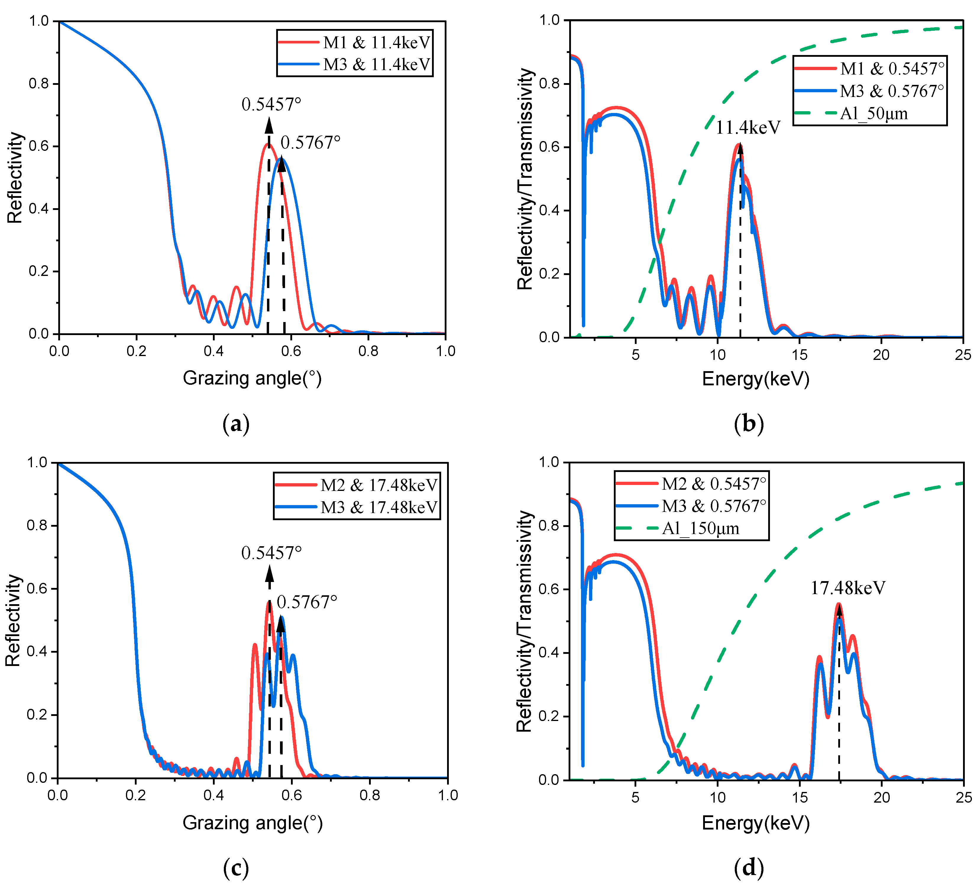
4. Performance Simulation

Because of the modulation effect of the periodic multilayer films, the intensity obtained at the image plane was nonuniform. Therefore, ray tracing programs were custom-written for this study to investigate the variation in the response efficiency of the high-energy KB microscope with FOV. The response efficiency ηKB can be expressed as follows:
η K B = Ω g e o ( x , z ) × R 1 ( x , z ) × R 2 ( x , z ) ,
where Ωgeo is the solid acceptance angle of the KB microscope, and R1 and R2 are the reflectivities of the point light source at the object plane (x, z) position through the mirrors M1 (or M2) and M3, respectively. The response efficiency, which reflects the KB microscope’s responsiveness to the target energy point, is directly proportional to the signal-to-noise ratio (SNR) of the X-ray image. Figure 4a,b show the simulated distribution of the response efficiency at the 11.4 and 17.48 keV energy points across the FOV. The response efficiency at the central FOV was 7.64 × 10⁻⁸ and 6.19 × 10⁻⁸ sr, respectively, which are of comparable magnitude to previous KB systems [18]. For the channel at 11.4 keV, the system’s reflectivity and aperture gradually decrease as the FOV moves away from the center, resulting in reduced response efficiency. The nonuniformity in the spectral response at the 17.48 keV energy point is primarily attributed to the modulating effect of the dual-period multilayer coating. The simulated response efficiency facilitates preliminary inversion of the hotspot intensity in 2D X-ray imaging [23].
The average spectral distribution at different FOV positions was simulated based on measurements of the reflectivity parameters of the two imaging channels, as shown in Figure 4c,d. By moving a point source with a divergence angle that covers the mirror aperture in the object plane, the effective rays that underwent two reflections were statistically analyzed to obtain the average energy values on the image plane. The results indicated that the spectral distributions within both channels exhibited a skewed symmetry, which is attributable to the distinct grazing incidence angles associated with different FOV positions. Within a FOV of 300 µm, the energy ranges for the two channels were 10.69–12.25 keV and 16.15–18.75 keV, respectively.

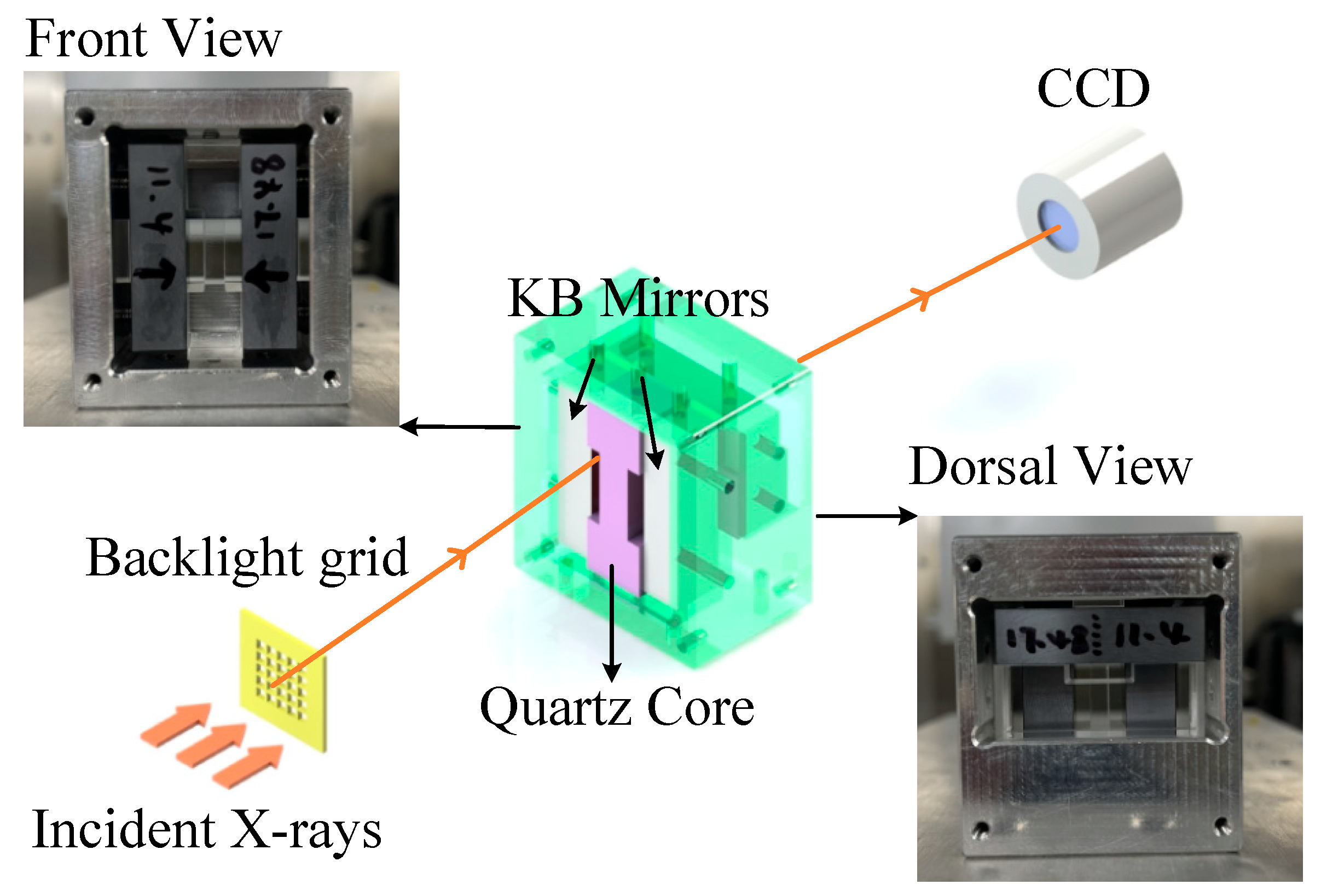
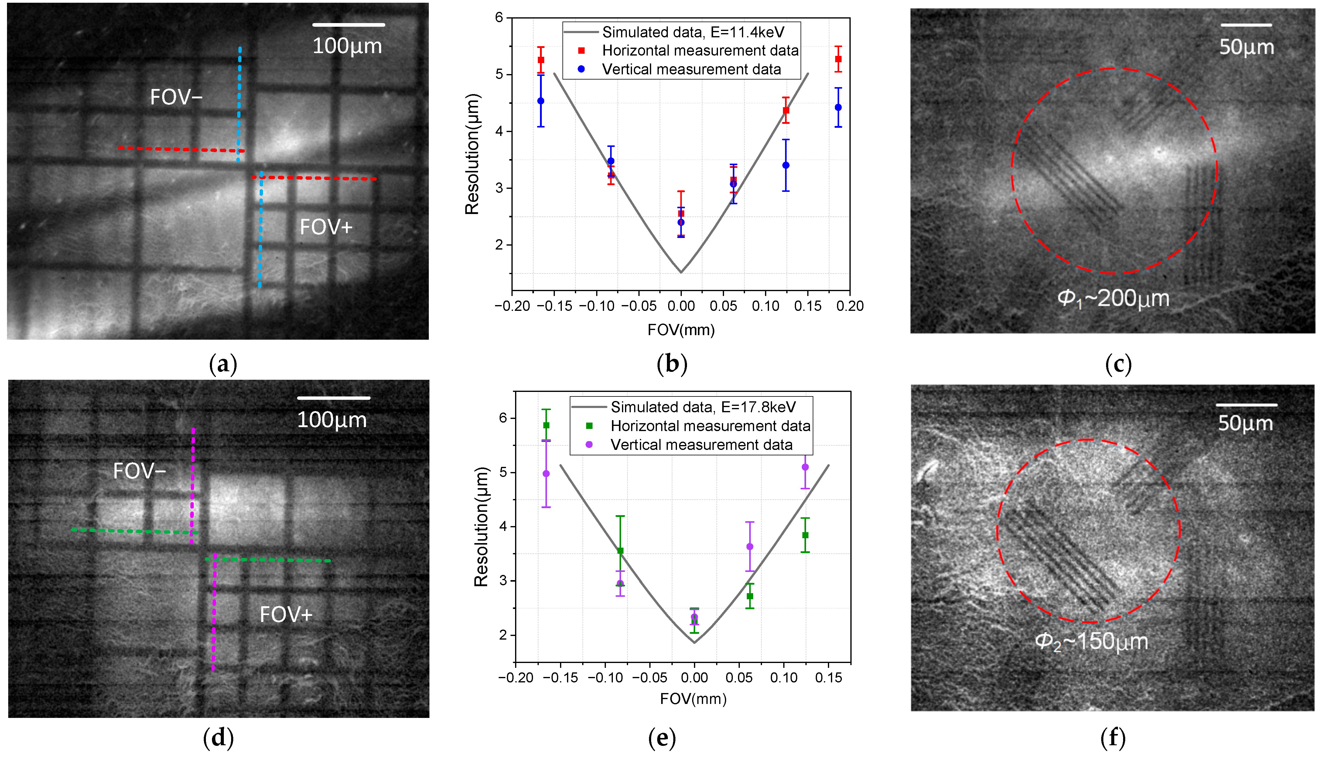
5. Imaging Experiment

Grid backlight imaging was performed in the laboratory to calibrate the spatial resolution of the microscope (Figure 5). The KB microscope is a grazing incidence system with a small numerical aperture. The larger the backlight source, the more the imaging area is illuminated. Because of the limited size and dispersion of the laboratory X-ray tube, it is necessary to position the emitted beam to align with the effective receiving aperture of the KB microscope. When the use of the X-ray tube as a backlight source is not sufficient to illuminate the entire FOV of the object side, the position of the backlight can be adjusted to compensate for this during the exposure of the charge-coupled device (CCD).
Grid imaging was performed using Au and Mo cathode tubes as backlights. The results are shown in Figure 6a,d. The white regions correspond to areas where X-rays pass through directly, while the black regions indicate areas where the intensity is significantly reduced due to absorption by the metal grid. The object plane consisted of a gold grid with a line width of 10 μm and four periods of 62, 83, 126, and 165 μm. The X-ray images were recorded using a hard X-ray CCD (PSL X-ray FDS 5.02 MP) with a source area of 12.5 mm × 10 mm and a pixel size of 4.54 μm. The upper and lower parts of Figure 6a were exposed for 450 s each under the Au X-ray tube conditions of 38 kV/22 mA. Figure 6d shows the image obtained at an exposure time of 1200 s under a 40 kV/30 mA Mo X-ray tube. The regions in the upper and left halves can be attributed to the bandwidth limitation of the film, which could not be improved by adjusting the backlight position.
The spatial resolution was calibrated using the conventional 10–90% standard [24]. It is obtained by dividing the distance corresponding to 10–90% of the intensity along the horizontal or vertical direction of the grid image edge by the magnification factor, as shown in the dashed line. Because this method is influenced by reading errors, several measurements were taken and error bars are given, as shown in Figure 6b,e. The spatial resolution was better than 3 μm at the center and better than 6.5 μm in an FOV of 300 μm. The solid black line represents the simulated spatial resolution curve based on a spatial resolution prediction model [25] of the KB microscope, which considers the influences of geometrical aberrations, diffraction effects, figure error, and surface roughness. For KB microscopes, the diffraction effect is primarily due to the aperture-like behavior of the two reflecting mirrors. Given that the wavelength of high-energy X-rays is significantly shorter than the system’s aperture, the spatial resolution degradation caused by diffraction effects is minimal. To more directly demonstrate the spatial resolution capability of the system, backlight imaging was performed with a resolution test card in the laboratory. The grid was replaced with a resolution test card of 4 μm line pairs by a dual optical path aiming lens. The results obtained by the CCD are shown in Figure 6c,f. The two channels resolved the line pairs within the FOV ranges of 200 and 150 μm. The difference in the SNR between the resolution test card and the grid can be attributed to the significantly smaller effective light-transmitting area of the former compared to the latter.

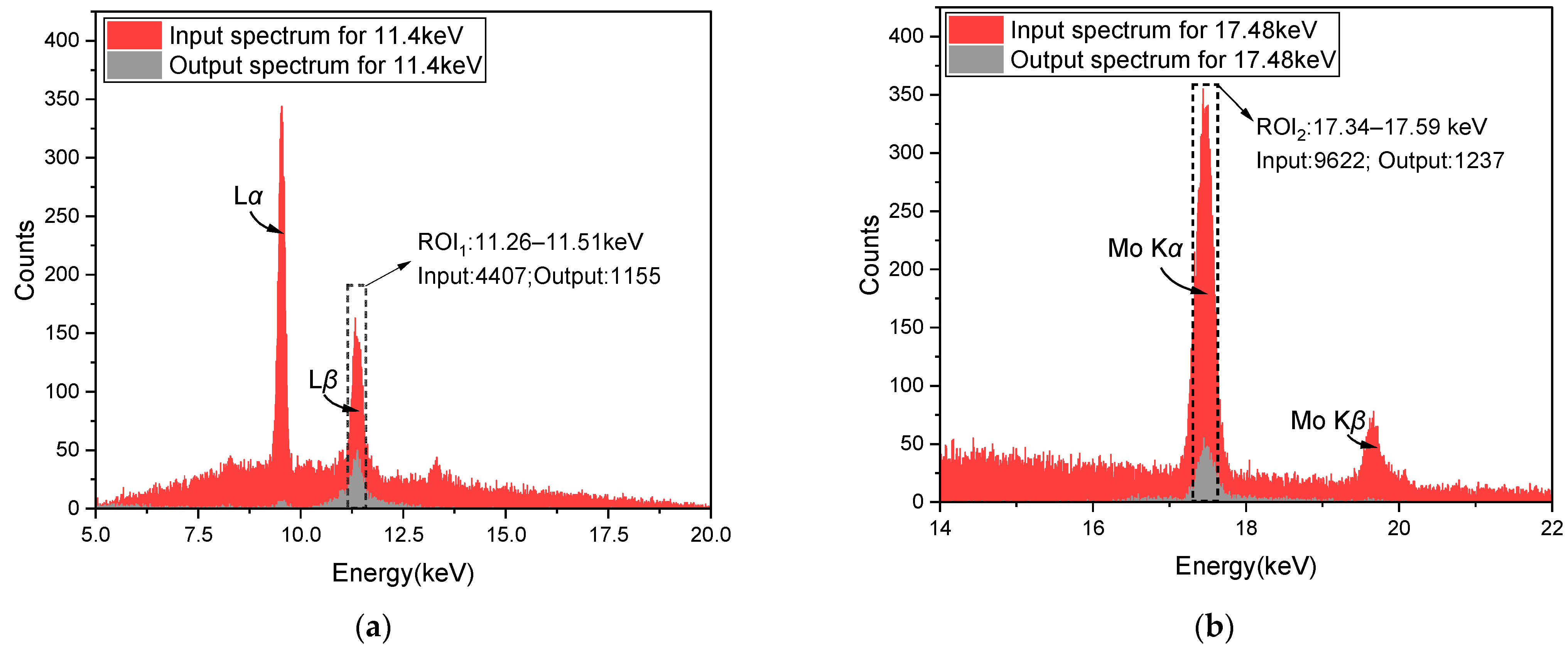
6. Spectral Response Measurements

After backlight imaging, spectral performance measurements were performed to verify that the system was operating at the designed energy point. The grazing incidence angles corresponding to the central FOV can be derived from the positional relationship between the direct image and the 2D image [24]. When the center of the FOV with the optimal spatial resolution is determined, the grazing incidence angle at this position typically deviates from the designed value. For the channel with an energy of 11.4 keV, the measured grazing incidence angles were 0.5472° and 0.5672°, whereas for the channel with an energy of 17.4 keV, the measured grazing incidence angles were 0.5403° and 0.5678°. Based on the measured grazing incidence angles, the calculated deviations between the spectral distribution center and the position of the optimal spatial resolution were 33.54 µm and 30.00 µm, respectively.
The spectra of the center FOV were calibrated using the previously described method [23]. The grid was replaced with a 15 μm pinhole made of tantalum, and the CCD was replaced with a Si-PIN detector (SDD) with a detection area of 5 mm × 5 mm. After measuring the intensity of the incident spectrum at the position of the 2D image, the KB system was removed, and the SDD was moved to the position of the direct beam to measure the incident spectrum. An aperture was placed in front of the SDD to limit its acceptance area and block stray light during the incident spectral measurements. To improve detection efficiency, the image distance during the entire process was reduced to 1000 mm. The current and voltage of the X-ray tube were set to 30 kV and 20 mA, respectively, and the SDD detection time was set to 30 s. The incident and emitted spectra of the two channels are shown in Figure 7. The central working energy points of the two channels were 11.38 and 17.45 keV, which proved that the spectral drift problem was mitigated. The response efficiency was calculated using the total photon count in the region of interest (ROI):
η K B _ t e s t = Ω o u t F o u t F i n ,
where Fout and Fin are the photon counts within the ROIs of the outgoing and incoming spectra, respectively, and Ωout is the stereo angle of the outgoing spectrum, which can be calculated from the aperture front SDD Sape and the image distance v as Ωout = Sape/v2. The calculated response efficiencies are 5.77 × 10⁻⁸ sr and 7.41 × 10⁻⁸ sr, and the computational errors from the theoretical values were 3.01% and 6.79%, respectively. The discrepancy between the measured and theoretical response efficiencies is primarily attributed to the inhomogeneity of the light source and the degradation of the mirrors in air.

7. Discussion

The proposed high-energy dual-channel KB system has significant implications for the measurement of hotspot electron temperature in ICF experiments. Unlike previous KB systems [15,18,19], which have been limited to lower energy (<10.2 keV), the microscope operates at 11.4 keV and 17.48 keV, thereby expanding the capability to probe higher electron temperatures and the evolution of high-density regions within the hotspot. Moreover, through the optimization of the multilayer design, the system effectively mitigates spectral drift issues at high energy points. The spatial and spectral domains were coupled through experimental alignment. Compared to multi-channel bent crystal imaging systems with normal incidence [26], the dual-channel configuration with nearly parallel incident rays reduces observational discrepancies between two channels.
The system will be employed at the Chinese Shenguang-III laser facility for the measurement of the electron temperature of hotspots. When coupled with a framing camera, the system is also capable of capturing the temporal evolution behavior of the hotspot. However, due to the limitations of off-axis aberrations in the KB microscope, it is challenging to further enhance the system’s spatial resolution. This issue could potentially be addressed by employing more complex configurations, such as the advanced KB structure [27]. Increasing the energy points further may exacerbate spectral drift issues, necessitating more precise calibration to couple the spatial and spectral centers.

8. Conclusions

In this study, we developed a dual-channel high-energy X-ray microscope that simultaneously achieves high spatial resolution and spectrally selective imaging at 11.4 and 17.48 keV energy points. The design and optimization results of the system were described in detail, and the system performance was evaluated in the laboratory by X-ray backlight imaging and spectral calibration. In backlight imaging, the spatial resolution of the central FOV was better than 3 μm, and the spatial resolution within the effective FOV of 300 μm was better than 6.5 μm. The energy spectral response centers of the two channels obtained using the spectral detector were 11.38 and 17.45 keV, respectively, which are consistent with the design results. The spectral response efficiencies of the central FOV were 7.41 × 10⁻⁸ and 5.77 × 10⁻⁸ sr, respectively, with deviations of 3.01% and 6.79% from the theoretical values. This system can be used for hotspot electron temperature measurements at China’s Shenguang-III laser facility.

Author Contributions

Conceptualization, M.L., J.X. and X.W.; Data curation, M.L., J.S. and X.W.; Formal analysis, J.X. and J.D.; Funding acquisition, J.D., K.R., W.L., X.Z. and D.Y.; Investigation, B.M.; Methodology, M.L., J.S. and M.W.; Project administration, B.M., X.Z. and D.Y.; Resources, K.R. and W.L.; Software, M.L., J.S. and M.W.; Supervision, W.L.; Visualization, J.S. and K.R.; Writing—original draft, M.L. and J.X.; Writing—review and editing, M.L., J.X., X.W. and B.M. All authors have read and agreed to the published version of the manuscript.

Funding

This research was funded by the National Key R&D Program of China, grant number 2023YFA1608400.

Institutional Review Board Statement

Not applicable.

Informed Consent Statement

Not applicable.

Data Availability Statement

Relevant data are available from the authors upon reasonable request.

Conflicts of Interest

The authors declare no conflicts of interest.

References

  1. Betti, R.; Hurricane, O.A. Inertial-confinement fusion with lasers. Nat. Phys. 2016, 12, 435–448. [Google Scholar] [CrossRef]
  2. Lindl, J.D.; Amendt, P.; Berger, R.L.; Glendinning, S.G.; Glenzer, S.H.; Haan, S.W.; Kauffman, R.L.; Landen, O.L.; Suter, L.J. The physics basis for ignition using indirect-drive targets on the National Ignition Facility. Phys. Plasmas 2004, 11, 339–491. [Google Scholar] [CrossRef]
  3. Kozioziemski, B.; Bachmann, B.; Do, A.; Tommasini, R. X-ray imaging methods for high-energy density physics applications. Rev. Sci. Instrum. 2023, 94, 041102. [Google Scholar] [CrossRef] [PubMed]
  4. Huntington, C.M.; Park, H.-S.; Maddox, B.R.; Barrios, M.A.; Benedetti, R.; Braun, D.G.; Hohenberger, M.; Landen, O.L.; Regan, S.P.; Wehrenberg, C.E.; et al. Developing a bright 17 keV X-ray source for probing high-energy-density states of matter at high spatial resolution. Phys. Plasmas 2015, 22, 043114. [Google Scholar] [CrossRef]
  5. Pickworth, L.A.; Hammel, B.A.; Smalyuk, V.A.; Robey, H.F.; Tommasini, R.; Benedetti, L.R.; Berzak Hopkins, L.; Bradley, D.K.; Dayton, M.; Felker, S.; et al. Development of new platforms for hydrodynamic instability and asymmetry measurements in deceleration phase of indirectly driven implosions on NIF. Phys. Plasmas 2018, 25, 082705. [Google Scholar] [CrossRef]
  6. Dewald, E.L.; Landen, O.L.; Salmonson, J.; Masse, L.; Tabak, M.; Smalyuk, V.A.; Schiaffino, S.; Heredia, R.; Schneider, M.; Nikroo, A. First study of Hohlraum x-ray preheat asymmetry inside an ICF capsule. Phys. Plasmas 2020, 27, 122703. [Google Scholar] [CrossRef]
  7. Weber, C.; Clark, D.; Pak, A.; Alfonso, N.; Bachmann, B.; Berzak Hopkins, L.; Bunn, T.; Crippen, J.; Divol, L.; Dittrich, T. Mixing in ICF implosions on the National Ignition Facility caused by the fill-tube. Phys. Plasmas 2020, 27, 032703. [Google Scholar] [CrossRef]
  8. Murphy, T.J.; Douglas, M.R.; Fincke, J.R.; Olson, R.E.; Cobble, J.A.; Haines, B.M.; Hamilton, C.E.; Lee, M.N.; Oertel, J.A.; Parra-Vasquez, N.A.G.; et al. Progress in the development of the MARBLE platform for studying thermonuclear burn in the presence of heterogeneous mix on OMEGA and the National Ignition Facility. J. Phys. Conf. Ser. 2016, 717, 012072. [Google Scholar] [CrossRef]
  9. Zhang, X.; Chen, Z.; Li, Y.; Mu, B.; Jiang, W.; Dong, J.; Yan, J.; Yu, B.; Xu, J.; Wang, X. A four-channels reflective Kirkpatrick-Baez microscope for the hot spot diagnostic in the 100 kJ laser driven inertial confinement fusion in China. J. Instrum. 2019, 14, C11010. [Google Scholar] [CrossRef]
  10. Ren, K.; Cao, Z.; Dong, J.; Mu, B.; Xie, Q.; Li, Y.; Zhang, J.; Huang, T.; Yang, J.; Wang, F.; et al. Note: New method for high-space-resolving hotspot electron temperature measurements on Shenguang-III prototype. Rev. Sci. Instrum. 2018, 89, 096108. [Google Scholar] [CrossRef]
  11. Badziak, J.; Jabłoński, S.; Wołowski, J. Progress and prospect of fast ignition of ICF targets. Plasma Phys. Control. Fusion. 2007, 49, B651. [Google Scholar] [CrossRef]
  12. McPherson, L.A.; Ampleford, D.J.; Coverdale, C.A.; Argo, J.W.; Owen, A.C.; Jaramillo, D.M. High energy X-ray pinhole imaging at the Z facility. Rev. Sci. Instrum. 2016, 87, 063502. [Google Scholar] [CrossRef]
  13. Laso Garcia, A.; Yang, L.; Bouffetier, V.; Appel, K.; Baehtz, C.; Hagemann, J.; Höppner, H.; Humphries, O.; Kluge, T.; Mishchenko, M.; et al. Cylindrical compression of thin wires by irradiation with a Joule-class short-pulse laser. Nat. Commun. 2024, 15, 7896. [Google Scholar] [CrossRef] [PubMed]
  14. Hall, G.N.; Krauland, C.M.; Schollmeier, M.S.; Kemp, G.E.; Buscho, J.G.; Hibbard, R.; Thompson, N.; Casco, E.R.; Ayers, M.J.; Ayers, S.L.; et al. The Crystal Backlighter Imager: A spherically bent crystal imager for radiography on the National Ignition Facility. Rev. Sci. Instrum. 2019, 90, 013702. [Google Scholar] [CrossRef] [PubMed]
  15. Pickworth, L.A.; Ayers, J.; Bell, P.; Brejnholt, N.F.; Buscho, J.G.; Bradley, D.; Decker, T.; Hau-Riege, S.; Kilkenny, J.; McCarville, T. The national ignition facility modular kirkpatrick-baez microscope. Rev. Sci. Instrum. 2016, 87, 11E316. [Google Scholar] [CrossRef] [PubMed]
  16. Kirkpatrick, P.; Baez, A.V. Formation of Optical Images by X-Rays. J. Opt. Soc. Am. 1948, 38, 766–774. [Google Scholar] [CrossRef]
  17. Gotchev, O.V.; Jaanimagi, P.A.; Knauer, J.P.; Marshall, F.J.; Meyerhofer, D.D.; Bassett, N.L.; Oliver, J.B. High-throughput, high-resolution Kirkpatrick–Baez microscope for advanced streaked imaging of ICF experiments on OMEGA. Rev. Sci. Instrum. 2003, 74, 2178–2181. [Google Scholar] [CrossRef]
  18. Li, W.; Mu, B.; Ren, K.; Xu, J.; Chen, L.; Li, M.; Xu, X.; Wang, X.; Liu, S.; Yi, R.; et al. Development of a quasi-coaxis dual-energy flat spectral response X-ray imaging instrument for measuring hotspot electron temperature. Opt. Express 2022, 30, 8777–8793. [Google Scholar] [CrossRef]
  19. Li, W.; Li, M.; Xu, J.; Li, J.; Chen, L.; Wang, X.; Mu, B.; Zhang, X.; Wang, F.; Wang, Z. Development of a four-color quasimonochromatic X-ray microscope for laser plasma research. Opt. Express 2024, 32, 22181–22193. [Google Scholar] [CrossRef]
  20. Troussel, P.; Dennetiere, D.; Maroni, R.; Høghøj, P.; Hedacq, S.; Cibik, L.; Krumrey, M. Multilayer optics for monochromatic high-resolution X-ray imaging diagnostic in a broad photon energy range from 2 keV to 22 keV. Nucl. Instrum. Methods Phys. Res. 2014, 767, 1–4. [Google Scholar] [CrossRef]
  21. Shimizu, K.; Omote, K. Multilayer optics for X-ray analysis. Rigaku J. 2008, 24, 1–9. [Google Scholar]
  22. Windt, D.L. IMD—Software for modeling the optical properties of multilayer films. Comput. Phys. 1998, 12, 360–370. [Google Scholar] [CrossRef]
  23. Li, M.; Wang, X.; Xu, J.; Li, W.; Xu, X.; Chen, L.; Mu, B. Study on full-aperture intensity response measurement for x-ray Kirkpatrick–Baez microscope. Opt. Eng. 2023, 62, 055103. [Google Scholar] [CrossRef]
  24. Friesen, H.; Tiedje, H.F.; Hey, D.S.; Mo, M.Z.; Beaudry, A.; Fedosejevs, R.; Tsui, Y.Y.; Mackinnon, A.; McLean, H.S.; Patel, P.K. Kirkpatrick-Baez microscope for hard X-ray imaging of fast ignition experiments. Rev. Sci. Instrum. 2013, 84, 023704. [Google Scholar] [CrossRef]
  25. Yi, S.; Mu, B.; Wang, X.; Huang, S.; Wang, Z. Resolution model of kirkpatrick-baez microscope with single-layer films. High Power Laser Part. Beams 2008, 20, 5. [Google Scholar]
  26. Jiang, C.; Xu, J.; Mu, B.; Wang, X.; Li, M.; Li, W.; Pu, Y.; Ding, Y. Four-channel toroidal crystal x-ray imager for laser-produced plasmas. Opt. Express 2021, 29, 6133–6146. [Google Scholar] [CrossRef]
  27. Kodama, R.; Ikeda, N.; Kato, Y.; Katori, Y.; Iwai, T.; Takeshi, K. Development of an advanced Kirkpatrick–Baez microscope. Opt. Lett. 1996, 21, 1321–1323. [Google Scholar] [CrossRef]
Figure 1. (a) Schematic of the high-energy KB microscope and its cross sections (b,c).
Photonics 12 00630 g001
Figure 2. Schematic diagrams of (a) periodic multilayer film at 11.4 keV and (b) double-period multilayer film at 17.48 keV. The heavy material (black) is W while the spacer layer (gray) is C.
Photonics 12 00630 g002
Figure 3. (a,c) Reflectivity versus grazing incidence angle and (b,d) reflectivity versus energy for 11.4 and 17.48 keV energy points. The green dotted lines show the transmissivity of the aluminum filter.
Photonics 12 00630 g003
Figure 4. (a,b) Response efficiency and (c,d) spectral distributions at the 11.4 and 17.48 keV energy points.
Photonics 12 00630 g004
Figure 5. Backlight experimental arrangement of the high-energy KB microscope.
Photonics 12 00630 g005
Figure 6. Grid backlighting results (a,d) and the corresponding spatial resolution calibration results (b,e). (c,f) Imaging results from the resolution test card. φ1 and φ2 are clear FOV regions marked with red dashed circles at the 11.4 and 17.48 keV energy points, respectively.
Photonics 12 00630 g006
Figure 7. Input and output spectrum for (a) 11.4 keV and (b) 17.48 keV. The incident spectrum was measured in the absence of the KB system. The ranges of ROI1 and ROI2 were 11.26–11.51 and 17.34–17.59 keV, respectively.
Photonics 12 00630 g007
Table 1. Optical parameters of the high-energy KB microscope.
MirrorUnitM1/M2M3
Mirror lengthmm1010
Radiusm40.040.0
Grazing angledeg0.54570.5767
Rotation angledeg0.63010.6549
Object distancemm200212
Image distancemm40003988
Magnification 20.018.8
Working energykeV11.4/17.4811.4/17.48
Table 2. Multilayer film parameters of mirrors M1, M2, and M3.
MirrorM1M2M3
Multilayer stacks6 W/C8 + 12 W/C6 W/C8 + 12 W/C
Energy (keV)11.417.4811.417.48
Grazing angle (°)0.54570.54570.57670.5767
Periodic thickness (nm)6.473.78 + 4.246.033.54 + 3.96
Peak reflectivity (%)60.7455.6956.0850.96
Angular bandwidth (°)0.0940.1020.0950.099
Thickness ratio0.50.50.510.51
Disclaimer/Publisher’s Note: The statements, opinions and data contained in all publications are solely those of the individual author(s) and contributor(s) and not of MDPI and/or the editor(s). MDPI and/or the editor(s) disclaim responsibility for any injury to people or property resulting from any ideas, methods, instructions or products referred to in the content.

